EP2409760B1 - Dispositif de traitement des gaz comprenant une zéolithe de type ferriérite/fer - Google Patents
Dispositif de traitement des gaz comprenant une zéolithe de type ferriérite/fer Download PDFInfo
- Publication number
- EP2409760B1 EP2409760B1 EP11174915.6A EP11174915A EP2409760B1 EP 2409760 B1 EP2409760 B1 EP 2409760B1 EP 11174915 A EP11174915 A EP 11174915A EP 2409760 B1 EP2409760 B1 EP 2409760B1
- Authority
- EP
- European Patent Office
- Prior art keywords
- composition
- diffraction
- catalytic
- zeolite
- iron
- Prior art date
- Legal status (The legal status is an assumption and is not a legal conclusion. Google has not performed a legal analysis and makes no representation as to the accuracy of the status listed.)
- Not-in-force
Links
Images





Classifications
-
- B—PERFORMING OPERATIONS; TRANSPORTING
- B01—PHYSICAL OR CHEMICAL PROCESSES OR APPARATUS IN GENERAL
- B01J—CHEMICAL OR PHYSICAL PROCESSES, e.g. CATALYSIS OR COLLOID CHEMISTRY; THEIR RELEVANT APPARATUS
- B01J35/00—Catalysts, in general, characterised by their form or physical properties
- B01J35/50—Catalysts, in general, characterised by their form or physical properties characterised by their shape or configuration
- B01J35/56—Foraminous structures having flow-through passages or channels, e.g. grids or three-dimensional [3D] monoliths
-
- B—PERFORMING OPERATIONS; TRANSPORTING
- B01—PHYSICAL OR CHEMICAL PROCESSES OR APPARATUS IN GENERAL
- B01D—SEPARATION
- B01D53/00—Separation of gases or vapours; Recovering vapours of volatile solvents from gases; Chemical or biological purification of waste gases, e.g. engine exhaust gases, smoke, fumes, flue gases, aerosols
- B01D53/34—Chemical or biological purification of waste gases
- B01D53/92—Chemical or biological purification of waste gases of engine exhaust gases
- B01D53/94—Chemical or biological purification of waste gases of engine exhaust gases by catalytic processes
- B01D53/9404—Removing only nitrogen compounds
- B01D53/9409—Nitrogen oxides
- B01D53/9413—Processes characterised by a specific catalyst
- B01D53/9418—Processes characterised by a specific catalyst for removing nitrogen oxides by selective catalytic reduction [SCR] using a reducing agent in a lean exhaust gas
-
- B—PERFORMING OPERATIONS; TRANSPORTING
- B01—PHYSICAL OR CHEMICAL PROCESSES OR APPARATUS IN GENERAL
- B01J—CHEMICAL OR PHYSICAL PROCESSES, e.g. CATALYSIS OR COLLOID CHEMISTRY; THEIR RELEVANT APPARATUS
- B01J23/00—Catalysts comprising metals or metal oxides or hydroxides, not provided for in group B01J21/00
- B01J23/70—Catalysts comprising metals or metal oxides or hydroxides, not provided for in group B01J21/00 of the iron group metals or copper
- B01J23/72—Copper
-
- B—PERFORMING OPERATIONS; TRANSPORTING
- B01—PHYSICAL OR CHEMICAL PROCESSES OR APPARATUS IN GENERAL
- B01J—CHEMICAL OR PHYSICAL PROCESSES, e.g. CATALYSIS OR COLLOID CHEMISTRY; THEIR RELEVANT APPARATUS
- B01J23/00—Catalysts comprising metals or metal oxides or hydroxides, not provided for in group B01J21/00
- B01J23/70—Catalysts comprising metals or metal oxides or hydroxides, not provided for in group B01J21/00 of the iron group metals or copper
- B01J23/74—Iron group metals
- B01J23/745—Iron
-
- B—PERFORMING OPERATIONS; TRANSPORTING
- B01—PHYSICAL OR CHEMICAL PROCESSES OR APPARATUS IN GENERAL
- B01J—CHEMICAL OR PHYSICAL PROCESSES, e.g. CATALYSIS OR COLLOID CHEMISTRY; THEIR RELEVANT APPARATUS
- B01J29/00—Catalysts comprising molecular sieves
- B01J29/04—Catalysts comprising molecular sieves having base-exchange properties, e.g. crystalline zeolites
- B01J29/06—Crystalline aluminosilicate zeolites; Isomorphous compounds thereof
- B01J29/65—Crystalline aluminosilicate zeolites; Isomorphous compounds thereof of the ferrierite type, e.g. types ZSM-21, ZSM-35 or ZSM-38, as exemplified by patent documents US4046859, US4016245 and US4046859, respectively
- B01J29/66—Crystalline aluminosilicate zeolites; Isomorphous compounds thereof of the ferrierite type, e.g. types ZSM-21, ZSM-35 or ZSM-38, as exemplified by patent documents US4046859, US4016245 and US4046859, respectively containing iron group metals, noble metals or copper
- B01J29/68—Iron group metals or copper
-
- B—PERFORMING OPERATIONS; TRANSPORTING
- B01—PHYSICAL OR CHEMICAL PROCESSES OR APPARATUS IN GENERAL
- B01J—CHEMICAL OR PHYSICAL PROCESSES, e.g. CATALYSIS OR COLLOID CHEMISTRY; THEIR RELEVANT APPARATUS
- B01J29/00—Catalysts comprising molecular sieves
- B01J29/82—Phosphates
- B01J29/84—Aluminophosphates containing other elements, e.g. metals, boron
- B01J29/85—Silicoaluminophosphates [SAPO compounds]
-
- B—PERFORMING OPERATIONS; TRANSPORTING
- B01—PHYSICAL OR CHEMICAL PROCESSES OR APPARATUS IN GENERAL
- B01J—CHEMICAL OR PHYSICAL PROCESSES, e.g. CATALYSIS OR COLLOID CHEMISTRY; THEIR RELEVANT APPARATUS
- B01J29/00—Catalysts comprising molecular sieves
- B01J29/90—Regeneration or reactivation
-
- B—PERFORMING OPERATIONS; TRANSPORTING
- B01—PHYSICAL OR CHEMICAL PROCESSES OR APPARATUS IN GENERAL
- B01J—CHEMICAL OR PHYSICAL PROCESSES, e.g. CATALYSIS OR COLLOID CHEMISTRY; THEIR RELEVANT APPARATUS
- B01J35/00—Catalysts, in general, characterised by their form or physical properties
- B01J35/70—Catalysts, in general, characterised by their form or physical properties characterised by their crystalline properties, e.g. semi-crystalline
-
- B—PERFORMING OPERATIONS; TRANSPORTING
- B01—PHYSICAL OR CHEMICAL PROCESSES OR APPARATUS IN GENERAL
- B01J—CHEMICAL OR PHYSICAL PROCESSES, e.g. CATALYSIS OR COLLOID CHEMISTRY; THEIR RELEVANT APPARATUS
- B01J37/00—Processes, in general, for preparing catalysts; Processes, in general, for activation of catalysts
- B01J37/02—Impregnation, coating or precipitation
- B01J37/0201—Impregnation
-
- B—PERFORMING OPERATIONS; TRANSPORTING
- B01—PHYSICAL OR CHEMICAL PROCESSES OR APPARATUS IN GENERAL
- B01J—CHEMICAL OR PHYSICAL PROCESSES, e.g. CATALYSIS OR COLLOID CHEMISTRY; THEIR RELEVANT APPARATUS
- B01J37/00—Processes, in general, for preparing catalysts; Processes, in general, for activation of catalysts
- B01J37/02—Impregnation, coating or precipitation
- B01J37/0215—Coating
-
- B—PERFORMING OPERATIONS; TRANSPORTING
- B01—PHYSICAL OR CHEMICAL PROCESSES OR APPARATUS IN GENERAL
- B01J—CHEMICAL OR PHYSICAL PROCESSES, e.g. CATALYSIS OR COLLOID CHEMISTRY; THEIR RELEVANT APPARATUS
- B01J37/00—Processes, in general, for preparing catalysts; Processes, in general, for activation of catalysts
- B01J37/30—Ion-exchange
-
- B—PERFORMING OPERATIONS; TRANSPORTING
- B01—PHYSICAL OR CHEMICAL PROCESSES OR APPARATUS IN GENERAL
- B01J—CHEMICAL OR PHYSICAL PROCESSES, e.g. CATALYSIS OR COLLOID CHEMISTRY; THEIR RELEVANT APPARATUS
- B01J38/00—Regeneration or reactivation of catalysts, in general
- B01J38/02—Heat treatment
-
- B—PERFORMING OPERATIONS; TRANSPORTING
- B01—PHYSICAL OR CHEMICAL PROCESSES OR APPARATUS IN GENERAL
- B01J—CHEMICAL OR PHYSICAL PROCESSES, e.g. CATALYSIS OR COLLOID CHEMISTRY; THEIR RELEVANT APPARATUS
- B01J38/00—Regeneration or reactivation of catalysts, in general
- B01J38/04—Gas or vapour treating; Treating by using liquids vaporisable upon contacting spent catalyst
- B01J38/06—Gas or vapour treating; Treating by using liquids vaporisable upon contacting spent catalyst using steam
-
- B—PERFORMING OPERATIONS; TRANSPORTING
- B01—PHYSICAL OR CHEMICAL PROCESSES OR APPARATUS IN GENERAL
- B01J—CHEMICAL OR PHYSICAL PROCESSES, e.g. CATALYSIS OR COLLOID CHEMISTRY; THEIR RELEVANT APPARATUS
- B01J38/00—Regeneration or reactivation of catalysts, in general
- B01J38/04—Gas or vapour treating; Treating by using liquids vaporisable upon contacting spent catalyst
- B01J38/12—Treating with free oxygen-containing gas
- B01J38/16—Oxidation gas comprising essentially steam and oxygen
-
- B—PERFORMING OPERATIONS; TRANSPORTING
- B01—PHYSICAL OR CHEMICAL PROCESSES OR APPARATUS IN GENERAL
- B01D—SEPARATION
- B01D2251/00—Reactants
- B01D2251/20—Reductants
- B01D2251/206—Ammonium compounds
- B01D2251/2062—Ammonia
-
- B—PERFORMING OPERATIONS; TRANSPORTING
- B01—PHYSICAL OR CHEMICAL PROCESSES OR APPARATUS IN GENERAL
- B01D—SEPARATION
- B01D2251/00—Reactants
- B01D2251/20—Reductants
- B01D2251/206—Ammonium compounds
- B01D2251/2067—Urea
-
- B—PERFORMING OPERATIONS; TRANSPORTING
- B01—PHYSICAL OR CHEMICAL PROCESSES OR APPARATUS IN GENERAL
- B01D—SEPARATION
- B01D2255/00—Catalysts
- B01D2255/20—Metals or compounds thereof
- B01D2255/207—Transition metals
- B01D2255/20738—Iron
-
- B—PERFORMING OPERATIONS; TRANSPORTING
- B01—PHYSICAL OR CHEMICAL PROCESSES OR APPARATUS IN GENERAL
- B01D—SEPARATION
- B01D2255/00—Catalysts
- B01D2255/50—Zeolites
-
- B—PERFORMING OPERATIONS; TRANSPORTING
- B01—PHYSICAL OR CHEMICAL PROCESSES OR APPARATUS IN GENERAL
- B01J—CHEMICAL OR PHYSICAL PROCESSES, e.g. CATALYSIS OR COLLOID CHEMISTRY; THEIR RELEVANT APPARATUS
- B01J2229/00—Aspects of molecular sieve catalysts not covered by B01J29/00
- B01J2229/10—After treatment, characterised by the effect to be obtained
- B01J2229/18—After treatment, characterised by the effect to be obtained to introduce other elements into or onto the molecular sieve itself
- B01J2229/186—After treatment, characterised by the effect to be obtained to introduce other elements into or onto the molecular sieve itself not in framework positions
-
- B—PERFORMING OPERATIONS; TRANSPORTING
- B01—PHYSICAL OR CHEMICAL PROCESSES OR APPARATUS IN GENERAL
- B01J—CHEMICAL OR PHYSICAL PROCESSES, e.g. CATALYSIS OR COLLOID CHEMISTRY; THEIR RELEVANT APPARATUS
- B01J2235/00—Indexing scheme associated with group B01J35/00, related to the analysis techniques used to determine the catalysts form or properties
-
- B—PERFORMING OPERATIONS; TRANSPORTING
- B01—PHYSICAL OR CHEMICAL PROCESSES OR APPARATUS IN GENERAL
- B01J—CHEMICAL OR PHYSICAL PROCESSES, e.g. CATALYSIS OR COLLOID CHEMISTRY; THEIR RELEVANT APPARATUS
- B01J2235/00—Indexing scheme associated with group B01J35/00, related to the analysis techniques used to determine the catalysts form or properties
- B01J2235/15—X-ray diffraction
-
- B—PERFORMING OPERATIONS; TRANSPORTING
- B01—PHYSICAL OR CHEMICAL PROCESSES OR APPARATUS IN GENERAL
- B01J—CHEMICAL OR PHYSICAL PROCESSES, e.g. CATALYSIS OR COLLOID CHEMISTRY; THEIR RELEVANT APPARATUS
- B01J35/00—Catalysts, in general, characterised by their form or physical properties
- B01J35/30—Catalysts, in general, characterised by their form or physical properties characterised by their physical properties
-
- F—MECHANICAL ENGINEERING; LIGHTING; HEATING; WEAPONS; BLASTING
- F01—MACHINES OR ENGINES IN GENERAL; ENGINE PLANTS IN GENERAL; STEAM ENGINES
- F01N—GAS-FLOW SILENCERS OR EXHAUST APPARATUS FOR MACHINES OR ENGINES IN GENERAL; GAS-FLOW SILENCERS OR EXHAUST APPARATUS FOR INTERNAL-COMBUSTION ENGINES
- F01N3/00—Exhaust or silencing apparatus having means for purifying, rendering innocuous, or otherwise treating exhaust
- F01N3/08—Exhaust or silencing apparatus having means for purifying, rendering innocuous, or otherwise treating exhaust for rendering innocuous
- F01N3/10—Exhaust or silencing apparatus having means for purifying, rendering innocuous, or otherwise treating exhaust for rendering innocuous by thermal or catalytic conversion of noxious components of exhaust
- F01N3/18—Exhaust or silencing apparatus having means for purifying, rendering innocuous, or otherwise treating exhaust for rendering innocuous by thermal or catalytic conversion of noxious components of exhaust characterised by methods of operation; Control
- F01N3/20—Exhaust or silencing apparatus having means for purifying, rendering innocuous, or otherwise treating exhaust for rendering innocuous by thermal or catalytic conversion of noxious components of exhaust characterised by methods of operation; Control specially adapted for catalytic conversion
- F01N3/206—Adding periodically or continuously substances to exhaust gases for promoting purification, e.g. catalytic material in liquid form, NOx reducing agents
- F01N3/2066—Selective catalytic reduction [SCR]
-
- Y—GENERAL TAGGING OF NEW TECHNOLOGICAL DEVELOPMENTS; GENERAL TAGGING OF CROSS-SECTIONAL TECHNOLOGIES SPANNING OVER SEVERAL SECTIONS OF THE IPC; TECHNICAL SUBJECTS COVERED BY FORMER USPC CROSS-REFERENCE ART COLLECTIONS [XRACs] AND DIGESTS
- Y02—TECHNOLOGIES OR APPLICATIONS FOR MITIGATION OR ADAPTATION AGAINST CLIMATE CHANGE
- Y02T—CLIMATE CHANGE MITIGATION TECHNOLOGIES RELATED TO TRANSPORTATION
- Y02T10/00—Road transport of goods or passengers
- Y02T10/10—Internal combustion engine [ICE] based vehicles
- Y02T10/12—Improving ICE efficiencies
Definitions
- the present invention relates to the field of catalysis for the reduction of nitrogen oxides by ammonia.
- nitrogen oxides mainly NO monoxide and NO 2 nitrogen dioxide, together referred to as NO x .
- One known technique for removing NO x is to selectively reduce these compounds.
- This technique is implemented by means of a catalytic device known as SCR (Selective Catalytic Reduction).
- SCR Selective Catalytic Reduction
- This technique consists in adding a catalytic NO x reduction device upstream or downstream of a particulate filter in the combustion gas exhaust system.
- the catalytic device comprises a specific catalytic composition and is used with ammonia as a reducing agent or a precursor of ammonia (for example urea).
- Catalytic compositions are known for the selective reduction of nitrogen oxides based on iron or copper deposited on a zeolite, however under difficult hydrothermal conditions such as those encountered in the exhaust gas of an internal combustion engine. Efficiency of the catalytic reduction of nitrogen oxides of these catalytic compositions declines.
- a particulate filter which may also be referred to as FAP, has a structure formed of a large number of alternately closed channels so that particulate-laden exhaust gases are forced through the porous walls of the fuel cell. body shaped honeycomb.
- a filter may be ceramic, for example cordierite or silicon carbide. It may also be sieves made of wire cloth, ceramic foam or fibrous materials.
- WO 2010/051983 discloses a particulate filter comprising two catalytic compositions.
- the catalyst to perform SCR function is deposited on the surface of the walls of the open channels on the side of the gas inlet.
- the oxidation catalyst is deposited on the surface of the walls of the open channels on the gas outlet side.
- the SCR catalyst may preferably contain an iron-exchanged zeolite.
- the zeolite is to be selected from a list comprising the ferrierite type, which is not used in the examples.
- the atomic ratio AI / Si is preferably greater than 10.
- the iron content (exchange rate) is not defined.
- the invention aims to solve one or more of these disadvantages.
- the invention thus relates to a catalytic composition as defined by claim 1. Indeed, it has been found that this catalytic composition retains its structure crystalline and therefore its catalytic properties despite hydrothermal treatments of the order of 1000 ° C.
- the invention also relates to a system for treating gas produced by combustion comprising at least one gas treatment device of the invention and means for introducing into the combustion gases a reducing agent comprising ammonia or a precursor of ammonia.
- the invention further relates to an internal combustion engine comprising a combustion gas treatment system of the invention.
- the engine is a diesel type engine or gasoline type direct injection.
- these types of internal combustion engines operate in a lean mixture and are nitrogen oxide generators, these nitrogen oxides to be treated.
- a particulate filter generally comprises a filter substrate or porous ceramic support having parallel channels 2. The latter are obstructed alternately by ceramic plugs 3 so as to force the exhaust gas whose direction of flow is illustrated by the arrows 4 to enter through inlet channels 2a, then through the porous dividing walls 5 to come out by exhaust gas outlet channels 2b.
- the filtering substrate may be chosen from common ceramics which are therefore economical, such as silicon carbide, alumina, aluminum titanate, cordierite or mullite. These ceramics also have a very good thermal resistance.
- the particulate filter 1 further comprises a catalyst composition for the selective catalytic reduction of nitrogen oxides.
- the catalytic composition consists of iron introduced into a ferrierite-type zeolite of acid form. Iron is essentially introduced by exchange of acid sites by iron (two acid sites being replaced by an iron atom).
- the catalytic composition of the invention is particularly suitable for the selective reduction of nitrogen oxides, especially with ammonia.
- the catalytic composition provided by the invention has improved hydrothermal stability relative to the prior art.
- Hydrothermal stability is understood to mean that the crystallographic structure of the catalytic composition, which can be characterized by X-ray diffraction, is not impaired. after aging at high temperature under the presence of water such as those caused by regeneration phases of the particulate filters, under real conditions on vehicle. It has been found that the crystalline structure of the catalytic composition of the invention is intact after a hydrothermal aging of 950 ° C. under a stream of air containing water vapor and is still intact after a hydrothermal aging of 1000 ° C. which makes it possible to preserve the conversion efficiency of the nitrogen oxides of the catalytic composition.
- the catalytic composition is effective at low temperature with a catalytic conversion rate of nitrogen oxides of greater than 40% from 225 ° C., even after for a hydrothermal aging of 1000 ° C.
- the catalytic conversion rates of the nitrogen oxides are relatively unaffected by the aging temperature. hydrothermal.
- a flue gas treatment device which combines in one unit a particulate filter and a catalyst for selective reduction of nitrogen oxides. This catalytic reduction is triggered by the addition of a reducing agent.
- the reducing agent is supplied to the combustion gases by suitable introduction means, such as an injector.
- suitable introduction means such as an injector.
- the means for introducing the reducing agent and the device for treating the combustion gases form a gas treatment system.
- the above catalytic composition is particularly suitable in the context of a selective catalytic reduction reaction of nitrogen oxides with ammonia.
- the selective reduction reaction of NO x is carried out by chemical reaction, catalyzed by the composition of the invention, between nitrogen oxides, NO x , contained in the flue gases and ammonia.
- the reducing agent provided by the introduction means can be ammonia as such or a precursor of ammonia, that is to say a solution capable of producing, after chemical reaction of gaseous ammonia.
- An example of a well-known ammonia precursor is urea.
- the means for introducing the reducing agent may be placed, relative to the flow direction of the combustion gases, upstream of the gas treatment device.
- the catalytic composition of the invention may be deposited on the surface of at least a portion of the porous separating walls of the channels 2 for passing the gases of the particle filter 1. The catalyst composition can then be deposited by a coating process.
- the filter substrate 1 is porous, at least part of the catalytic composition can also be deposited in the porosity of said substrate, in other words in the porous separating walls.
- the above gas treatment system is particularly applicable in the treatment of gases produced by combustion of an internal combustion engine.
- a flue gas treatment system is particularly suitable for reducing the nitrogen oxides produced by a diesel engine or a stratified direct injection gasoline engine, that is to say for which the injection of gasoline is performed during the engine compression phase.
- ammonia as the reducing agent as an example, the operation is as follows: the introduction means supply ammonia to the combustion gases, which mixes with the combustion gases upstream of the gas treatment device. The combustion gases comprising the ammonia then enters the gas treatment device.
- the selective reduction reaction of NO x is then carried out by chemical reaction between the nitrogen oxides contained in the combustion gases and ammonia, the chemical reaction being catalyzed by the catalytic composition of the invention.
- the combustion gases pass through the filter substrate which retains the soot particles.
- a catalytic composition A according to the state of the art was synthesized by following the teaching of the document WO2009 / 099937 on behalf of BASF.
- the catalytic composition A dried at 90 ° C. is 2.75% copper, Cu, on a zeolite silicoaluminophosphate, called SAPO 34.
- the catalytic composition A is then coated on a core of cordierite monolith and then calcined for 5 hours at 550 ° C. to form a catalytic device or catalyst.
- the charge of catalytic composition A in the new catalytic device is 126 g / l of monolith.
- the active phase of the catalyst composition A dried at 90 ° C is then aged at 850 ° C for 5 h, then at 900 ° C for 5 h and finally at 950 ° C for 5 h.
- the Cu / SAPO 34 catalytic composition is characterized by X-ray diffraction to determine the crystallographic structure.
- the diffraction spectra of the samples of catalytic composition A aged at 850 ° C., 900 ° C. and 950 ° C. are respectively reported to Figures 2, 3 and 4 .
- the diffraction spectra of Figures 2 and 3 are substantially identical and show that the crystallographic structure is stable for aging at 850 ° C and 900 ° C, while the figure 4 shows that the crystallographic structure of SAPO 34 is destroyed after aging at 950 ° C.
- Catalytic composition B consists of 0.67% iron, introduced into a zeolite of ferrierite type in acid initial form, whose Si / Al atomic ratio is 27.5.
- a Ferrierite zeolite in acidic form denotes, in a known manner, a zeolite for which aluminum, in the form of an Al - ion, is associated with hydrogen in the form of an H + ion.
- Ferrierite is a zeolite with two channel networks with pore openings of 4.3 ⁇ x 5.5 ⁇ and 3.4 ⁇ x 4.8 ⁇ .
- the acid site is exchanged for this zeolite by Fe 2 + with an aqueous solution of FeSO 4 7H 2 O iron sulphate; the exchange conditions are as follows: 50 g of zeolite are suspended and with stirring in 150 cm 3 of a solution of iron sulphate (at 1 mol / liter or 278 g FeSO 4 7H 2 O / liter). The temperature is 60 ° C and the exchange time 4 hours.
- the Fe 2 + exchanged zeolite is filtered on a filter funnel and then washed in percolation with one liter of demineralized water whose conductivity is less than 10 ⁇ siemens.
- the filter cake is dried in an oven at 100 ° C .; the iron content measured by ICP (Induced Coupled Plasma) is 0.7% by weight.
- This zeolite is then coated on a 400 cpsi honeycomb substrate (400 channels per square inch, ie 62 channels per cm 2 ).
- the carrot has a diameter of 2. 54 cm and a height of 5.08 cm, a volume of 25 cm 3 .
- the binder used is a pseudobohemite-type alumina; the binder content expressed as Al 2 O 3 is 20% by weight.
- the active ingredient content is 158 g / l.
- the aging treatment is carried out in a swept furnace of an air mixture comprising 10% H 2 O for 5 hours at the following temperatures: 850 ° C, 900 ° C, 950 ° C and 1000 ° C.
- a sample of the powdered catalyst composition B also undergoes the same treatment for X-ray diffraction analysis.
- This hydrothermal treatment is applied to represent the hydrothermal aging that the catalyst compositions will undergo during the regeneration of the particulate filters under real conditions on the vehicle.
- the catalytic composition C consists of 0.7% iron, introduced into a zeolite ferrierite type initial acid form whose Si / Al atomic ratio is 8.8.
- the acidic sites of this zeolite are exchanged with Fe 2 + with an aqueous FeSO 4 7H 2 O iron sulphate solution; the exchange conditions are as follows: 50 g of zeolite are suspended and with stirring in 150 cm 3 of a solution of iron sulphate (at 1 mol / liter or 278 g FeSO 4 7H 2 O / liter). The temperature is 60 ° C and the exchange time 4 hours.
- the Fe 2 + exchanged zeolite is filtered on a filter funnel and then washed in percolation with one liter of demineralized water whose conductivity is less than 10 ⁇ siemens.
- the filter cake is dried in an oven at 100 C; the iron content measured by ICP is 0.7% by weight.
- This zeolite is then coated on a 400 cpsi honeycomb substrate (400 channels per square inch, ie 62 channels per cm 2 ).
- the carrot has a diameter of 2. 54 cm and a height of 5.08 cm, a volume of 25 cm 3 .
- the binder used is a pseudobohemite-type alumina.
- the binder content expressed in Al 2 O 3 is 20% by weight.
- the active ingredient content is 134 g / l.
- the aging treatment is carried out in a swept furnace of an air mixture comprising 10% H 2 O for 5 hours at the following temperatures: 850 ° C, 900 ° C, 950 ° C and 1000 ° C.
- a sample of the powdered catalyst composition B also undergoes the same treatment for X-ray diffraction analysis.
- the reference A0 denotes the catalytic composition A without aging
- the reference A1 designates the catalytic composition A having undergone aging at 850 ° C.
- the reference A2 designates the catalytic composition A having undergone aging at 900 ° C.
- the reference A3 designates the catalytic composition A having aged at 950 ° C.
- the reference B0 designates the catalyst composition B without aging
- the reference B1 designates the catalytic composition B having aged at 850 ° C
- the reference B2 designates the catalytic composition B having undergone aging at 900 ° C
- the reference B3 designates the catalytic composition B having aged at 950 ° C
- the reference B4 designates the catalytic composition B having undergone aging at 1000 ° C.
- the reference C0 denotes the catalytic composition C without aging
- the reference C1 designates the catalytic composition C having undergone aging at 850 ° C.
- the reference C2 denotes the catalytic composition C having undergone aging at 900 ° C.
- the reference C3 designates the catalytic composition C having aged at 950 ° C.
- the reference C4 denotes the catalytic composition C having undergone aging at 1000 ° C.
- the catalyst compositions A0, A1 and A2 have good NO x conversion, greater than 60%.
- the catalytic compositions B and C presented to Figures 15 and 16 according to the invention have a very good hydrothermal stability and high efficiency in reducing NO x after aging at 950 ° C and after aging at 1000 ° C.
Landscapes
- Chemical & Material Sciences (AREA)
- Engineering & Computer Science (AREA)
- Chemical Kinetics & Catalysis (AREA)
- Materials Engineering (AREA)
- Organic Chemistry (AREA)
- Environmental & Geological Engineering (AREA)
- Health & Medical Sciences (AREA)
- Biomedical Technology (AREA)
- Combustion & Propulsion (AREA)
- Analytical Chemistry (AREA)
- General Chemical & Material Sciences (AREA)
- Oil, Petroleum & Natural Gas (AREA)
- Physics & Mathematics (AREA)
- Thermal Sciences (AREA)
- Crystallography & Structural Chemistry (AREA)
- Catalysts (AREA)
- Exhaust Gas Treatment By Means Of Catalyst (AREA)
Description
- La présente invention se rapporte au domaine de la catalyse pour la réduction des oxydes d'azote par l'ammoniac.
- Depuis de nombreuses années, les constructeurs de véhicules automobiles à moteur thermique font beaucoup d'efforts pour réduire l'émission dans l'atmosphère de composés chimiques nuisibles à l'environnement produits par les moteurs thermiques lors de la combustion du carburant.
- Parmi ces composés, on trouve les oxydes d'azote, principalement le monoxyde NO et le dioxyde NO2 d'azote, désignés ensemble sous l'abréviation NOx.
- Une technique connue pour éliminer les NOx consiste à réduire sélectivement ces composés. Cette technique est mise en oeuvre au moyen d'un dispositif catalytique dit SCR (« Selective Catalytic Réduction »). Cette technique consiste à ajouter un dispositif catalytique de réduction des NOx en amont ou en aval d'un filtre à particules dans le circuit d'échappement des gaz de combustion. Le dispositif catalytique comprend une composition catalytique spécifique et est utilisé avec de l'ammoniac à titre d'agent réducteur ou un précurseur de l'ammoniac (par exemple de l'urée).
- On connait des compositions catalytiques pour la réduction sélective des oxydes d'azote à base de fer ou de cuivre déposé sur une zéolithe, cependant sous des conditions hydrothermales difficiles telles que celle rencontrées dans les gaz d'échappement de moteur à combustion interne, l'efficacité de la réduction catalytique des oxydes d'azote de ces compositions catalytiques décline.
- On connait du document
WO2009099937 une composition catalytique comprenant du cuivre déposé sur une zéolithe silico-alumino-phosphate (SAPO-34). Cette composition catalytique présente une stabilité hydrothermale que jusqu'à 850°C. - De manière générale, l'efficacité de la réduction catalytique SCR n'est pas non plus satisfaisante à basse température.
Un filtre à particules, que l'on peut désignera aussi sous le sigle FAP, présente une structure formée d'un grand nombre de canaux fermés alternativement pour que les gaz d'échappement chargés de particules soient obligés de passer à travers les parois poreuses du corps en forme de nid d'abeille. Un tel filtre peut être en céramique, par exemple en cordiérite ou en carbure de silicium. Il peut aussi s'agir de tamis en toile métallique, en mousse céramique ou en matériaux fibreux.
On connait, par exemple du documentEP1617051 un système SCR/FAP intégré pour lequel les parois du filtre à particules peuvent être imprégnées d'une composition catalytique SCR. Pour garantir la réduction voulue, il faut de temps en temps éliminer les particules de suies accumulées dans le filtre à particules. Cela se fait en général en brûlant les particules à une température élevée du filtre. Il s'agit de la régénération thermique du filtre. Dans le cas de cas d'un véhicule équipé d'un moteur diesel, cette régénération se fait de manière caractéristique par élévation de la température des gaz d'échappement. Les niveaux de température atteint dans le filtre dégradent l'efficacité de la réduction catalytique SCR. - Il est connu par le document
WO2009/135588 (et le documentUS 2011/0056187 correspondant) que la stabilité thermique d'un zéolithe ferriérite échangée avec du fer (0.1 - 10% en poids et de préférence entre 1-8%) dans un procédé SCR est meilleure que celle d'un zéolithe « béta » échangée avec du fer, avec une phase de test dépassant 1000°C pour un zéolithe expérimental avec du fer à 3,5%. -
WO 2010/051983 décrit un filtre à particules comprenant deux compositions catalytiques. Le catalyseur devant remplir la fonction SCR est déposé sur la surface des parois des canaux ouverts du côté de l'entrée des gaz. Le catalyseur d'oxydation est déposé sur la surface des parois des canaux ouverts du côté de la sortie des gaz. Le catalyseur SCR peut contenir de préférence une zéolithe échangée au fer. La zéolithe est à sélectionner dans une liste comprenant le type ferriérite, qui n'est pas utilisée dans les exemples. Le rapport atomique AI/Si est de préférence supérieur à 10. La teneur en fer (taux d'échange) n'est pas définie. - Il existe donc un besoin pour mettre au point une composition catalytique présentant une plus grande fenêtre de fonctionnement, en étant notamment plus efficace à basse température et à haute température et apte à subir des pics thermiques sans dégradations des performances catalytiques. Ce besoin est particulièrement important dans le cas des moteurs Diesel ou essence à injection directe essence stratifié (mélange pauvre).
- L'invention vise à résoudre un ou plusieurs de ces inconvénients.
L'invention porte ainsi sur une composition catalytique telle que définie par la revendication 1. En effet il est apparu que cette composition catalytique garde sa structure cristalline et donc ses propriétés catalytiques malgré des traitements hydrothermaux de l'ordre de 1000°C. - L'invention concerne aussi un système de traitement de gaz produits par combustion comprenant au moins un dispositif de traitement de gaz de l'invention et des moyens d'introduction dans les gaz de combustion d'un agent réducteur comprenant de l'ammoniac ou un précurseur de l'ammoniac.
- L'invention concerne encore un moteur à combustion interne comprenant un système de traitement des gaz produits par combustion de l'invention.
- De préférence, il s'agit d'un moteur de type diesel ou de type essence à injection directe. En effet, ces types de moteurs à combustion interne fonctionnent en mélange pauvre et sont générateurs d'oxydes d'azote, ces oxydes d'azote devant être traités.
- D'autres particularités et avantages apparaîtront à la lecture de la description ci-après d'un mode particulier de réalisation, non limitatif de l'invention, faite en référence aux figures dans lesquelles :
- La
figure 1 est une représentation schématique de la structure interne d'un filtre à particules. - La
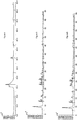
figure 2 est un spectre de diffraction de rayons X (DRX) de la composition catalytique A, vieillie à 850°C pendant 5 heures. L'angle de diffraction est représenté en abscisses et l'intensité de diffraction est représentée en ordonnées. - La
figure 3 est un spectre de diffraction de rayons X (DRX) de la composition catalytique A, vieillie à 900°C pendant 5 heures. L'angle de diffraction est représenté en abscisses et l'intensité de diffraction est représentée en ordonnées. - La
figure 4 est un spectre de diffraction de rayons X (DRX) de la composition catalytique A, vieillie à 950°C pendant 5 heures. L'angle de diffraction est représenté en abscisses et l'intensité de diffraction est représentée en ordonnées. - La
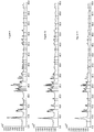
figure 5 est un spectre de diffraction de rayons X (DRX) de la composition catalytique B, vieillie à 850°C pendant 5 heures. L'angle de diffraction est représenté en abscisses et l'intensité de diffraction est représentée en ordonnées. - La
figure 6 est un spectre de diffraction de rayons X (DRX) de la composition catalytique B, vieillie à 900°C pendant 5 heures. L'angle de diffraction est représenté en abscisses et l'intensité de diffraction est représentée en ordonnées. - La
figure 7 est un spectre de diffraction de rayons X (DRX) de la composition catalytique B, vieillie à 950°C pendant 5 heures. L'angle de diffraction est représenté en abscisses et l'intensité de diffraction est représentée en ordonnées. - La
figure 8 est un spectre de diffraction de rayons X (DRX) de la composition catalytique B, vieillie à 1000°C pendant 5 heures. L'angle de diffraction est représenté en abscisses et l'intensité de diffraction est représentée en ordonnées. - La
figure 9 est un spectre de diffraction de rayons X (DRX) de la composition catalytique C, non vieillie. L'angle de diffraction est représenté en abscisses et l'intensité de diffraction est représentée en ordonnées. - La
figure 10 est un spectre de diffraction de rayons X (DRX) de la composition catalytique C, vieillie à 850°C pendant 5 heures. L'angle de diffraction est représenté en abscisses et l'intensité de diffraction est représentée en ordonnées. - La
figure 11 est un spectre de diffraction de rayons X (DRX) de la composition catalytique C, vieillie à 900°C pendant 5 heures. L'angle de diffraction est représenté en abscisses et l'intensité de diffraction est représentée en ordonnées. - La
figure 12 est un spectre de diffraction de rayons X (DRX) de la composition catalytique C, vieillie à 950°C pendant 5 heures. L'angle de diffraction est représenté en abscisses et l'intensité de diffraction est représentée en ordonnées. - La
figure 13 est un spectre de diffraction de rayons X (DRX) de la composition catalytique C, vieillie à 1000°C pendant 5 heures. L'angle de diffraction est représenté en abscisses et l'intensité de diffraction est représentée en ordonnées. - La
figure 14 est un graphe présentant le taux de conversion des oxydes d'azote en fonction de la température de gaz, pour la composition catalytique A ayant subie un traitement hydrothermal à 850°C, 900°C et 950°C. - La
figure 15 est un graphe présentant le taux de conversion des oxydes d'azote en fonction de la température de gaz, pour la composition catalytique B ayant subie un traitement hydrothermal à 850°C, 900°C, 950°C et 1000°C. - La
figure 16 est un graphe présentant le taux de conversion des oxydes d'azote en fonction de la température de gaz, pour la composition catalytique C ayant subie un traitement hydrothermal à 850°C, 900°C, 950°C et 1000°C. - La
figure 1 rappelle schématiquement la structure interne connue en soi d'un filtre 1 à particules. Un filtre à particules comprend généralement un substrat filtrant ou support céramique poreux comportant des canaux 2 parallèles. Ces derniers sont obstrués en alternance par des bouchons 3 céramiques de manière à forcer les gaz d'échappement dont le sens de circulation est illustré par les flèches 4 à entrer par des canaux 2a d'entrée, puis traverser les parois séparatrices 5 poreuses pour ressortir par des canaux 2b de sortie des gaz d'échappement.
Le substrat filtrant peut être choisi parmi des céramiques courantes donc économiques comme de préférence le carbure de silicium, l'alumine, le titanate d'aluminium, la cordiérite, la mullite. Ces céramiques présentent en outre une très bonne tenue thermique.
Le filtre à particules 1 comprend de plus une composition catalytique permettant la réduction catalytique sélective des oxydes d'azote. Un tel filtre à particules 1 permet de surmonter les inconvénients de l'état de la technique. Il permet dans une même structure interne non seulement de filtrer les particules de suie contenues dans les gaz d'échappement mais aussi de réduire plus efficacement les oxydes d'azote. On obtient donc un dispositif de traitement des gaz plus compact et plus économique puisque deux fonctions de traitement des gaz sont réunies sur un même support.
Conformément à l'invention, la composition catalytique est constituée de fer introduit dans une zéolite de type ferriérite de forme acide. Le fer est essentiellement introduit par échange des sites acides par le fer (deux sites acides étant remplacés par un atome de fer). La composition catalytique de l'invention est particulièrement adaptée à la de réduction sélective des oxydes d'azote, notamment par l'ammoniac. - Dans les proportions définies précédemment, la composition catalytique fournie par l'invention présente une stabilité hydrothermale améliorée relativement à l'art antérieur. On entend par stabilité hydrothermale le fait que la structure cristallographique de la composition catalytique, qui peut être caractérisée par diffraction X, n'est pas altérée après des vieillissements à haute température sous présence d'eau tels que ceux provoqués par des phases de régénération des filtres à particules, dans les conditions réelles sur véhicule. Il est apparu que la structure cristalline de la composition catalytique de l'invention est intacte après un vieillissement hydrothermal de 950°C sous flux d'air contenant de la vapeur d'eau et est toujours intacte après un vieillissement hydrothermal de 1000°C, ce qui permet de préserver l'efficacité de conversion des oxydes d'azote de la composition catalytique.
- Par ailleurs, pour un rapport atomique Si/AI de la ferriérite compris entre 8 et 30, la composition catalytique est efficace à basse température avec un taux de conversion catalytique des oxydes d'azote supérieur à 40% dès 225°C, y compris après pour un vieillissement hydrothermal de 1000°C.
- En outre, pour une proportion massique de fer dans la composition catalytique comprise entre 0,3% et 2%, les taux de conversion catalytique des oxydes d'azote, à une température de fonctionnement déterminée, sont relativement peu affectés par la température de vieillissement hydrothermal.
- C'est cette meilleure tenue aux conditions de traitements hydrothermaux représentatives de conditions représentative rencontrées lors d'une phase de régénération qui rend possible l'intégration de la composition catalytique au substrat du filtre 1 à particules. On obtient ainsi un dispositif de traitement des gaz de combustion qui réunit en une unité un filtre à particules et un catalyseur de réduction sélective des oxydes d'azote. Cette réduction catalytique est déclenchée par l'apport d'un agent réducteur. L'agent réducteur est apporté dans les gaz de combustion par des moyens d'introduction adaptés, tel qu'un injecteur. Les moyens d'introduction de l'agent réducteur et le dispositif de dispositif de traitement des gaz de combustion forme un système de traitement des gaz.
- La composition catalytique ci-dessus est particulièrement appropriée dans le cadre d'une réaction de réduction catalytique sélective des oxydes d'azote par de l'ammoniac. La réaction de réduction sélective des NOx s'effectue par réaction chimique, catalysée par la composition de l'invention, entre les oxydes d'azote, NOx, contenus dans les gaz de combustion et l'ammoniac.
- L'agent réducteur apporté par les moyens d'introduction peut être de l'ammoniac en tant que tel ou encore un précurseur de l'ammoniac, c'est-à-dire une solution apte à produire, après réaction chimique de l'ammoniac gazeux. Un exemple de précurseur de l'ammoniac très connu est l'urée.
De manière connue les moyens d'introduction de l'agent réducteur peuvent être placés, relativement au sens de circulation des gaz de combustion, en amont du dispositif de traitement des gaz.
La composition catalytique de l'invention peut être déposée en surface sur au moins une partie des parois séparatrices 5 poreuses des canaux 2 de passage des gaz du filtre 1 à particules. La composition catalytique peut alors être déposée par un procédé d'enduction. Le substrat filtrant 1 étant poreux, au moins une partie de la composition catalytique peut aussi être déposée dans la porosité dudit substrat, autrement dit dans les parois séparatrices 5 poreuses.
Le système de traitement des gaz ci-dessus trouve particulièrement à s'appliquer dans le cadre du traitement des gaz produits par combustion d'un moteur à combustion interne.
Un tel système de traitement des gaz de combustion est particulièrement adapté à la réduction des oxydes d'azote produits par un moteur Diesel ou un moteur à essence à injection directe stratifié, c'est-à-dire pour lequel l'injection d'essence est réalisée durant la phase de compression moteur.
En prenant comme exemple, l'ammoniac comme agent réducteur, le fonctionnement est le suivant : les moyens d'introduction apportent dans les gaz de combustion l'ammoniac qui se mélange aux gaz de combustion en amont du dispositif de traitement des gaz. Les gaz de combustion comprenant l'ammoniac entre ensuite dans le dispositif de traitement des gaz. La réaction de réduction sélective des NOx s'effectue alors par réaction chimique entre les oxydes d'azote contenus dans les gaz de combustion et l'ammoniac, la réaction chimique étant catalysée par la composition catalytique de l'invention. En outre les gaz de combustion traversent le substrat filtrant qui en retient les particules de suies. - Une composition catalytique A selon l'état de la technique a été synthétisé en suivant l'enseignement du document
WO2009/099937 au nom de BASF. - La composition catalytique A séché à 90°C est de 2,75% de cuivre, Cu, sur une zéolithe silico-alumino-phosphate, dénommée SAPO 34.
- La composition catalytique A est ensuite enduite sur une carotte de monolithe en cordiérite puis calcinée pendant 5h à 550°C pour former un dispositif catalytique ou catalyseur. La charge en composition catalytique A dans le dispositif catalytique neuf est de 126g/l de monolithe.
- La phase active de la composition catalytique A séchée à 90°C est ensuite vieillie à 850°C pendant 5 h, puis à 900°C pendant 5 h et enfin à 950°C pendant 5 h.
- Après vieillissement, la composition catalytique A Cu/SAPO 34 est caractérisée par diffraction des rayons X pour déterminer la structure cristallographique.
- Les spectres de diffractions des échantillons de composition catalytique A vieillis à 850°C, 900°C et 950°C sont reportés respectivement aux
figures 2, 3 et4 . Les spectres de diffraction desfigures 2 et 3 sont sensiblement identiques et montrent que la structure cristallographique est stable pour des vieillissements à 850°C et 900°C, tandis que lafigure 4 montre que la structure cristallographique du SAPO 34 est détruite après le vieillissement à 950°C. - La composition catalytique B est constituée de 0,67 % de Fer, introduit dans une zéolithe de type ferriérite sous forme initiale acide, dont le rapport Si/AI atomique est de 27,5. Une zéolithe ferriérite sous forme acide désigne de manière connue une zéolithe pour laquelle l'aluminium, sous forme d'ion Al-, est associé à de l'hydrogène sous forme d'ion H+.
- La ferriérite est une zéolithe qui comporte deux réseaux de canaux dont les ouvertures de pores sont 4.3 Å x 5.5 Å et 3.4 Å x 4.8 Å.
- On procède à l'échange de site acide de cette zéolithe par Fe2 + avec une solution aqueuse de sulfate de fer FeSO47H2O ; les conditions d'échange sont les suivantes :
50 g de zéolithe sont mis en suspension et sous agitation dans 150 cm3 d'une solution de sulfate de fer (à 1 mole/litre soit 278 g FeSO47H2O/litre). La température est de 60 °C et le temps d'échange de 4 heures. - La zéolithe échangée Fe2 + est filtrée sur un entonnoir filtrant puis lavé en percolation avec un litre d'eau déminéralisée dont la conductivité est inférieure à 10 µsiemens.
- Le gâteau de filtre est séché à l'étuve à 100 °C ; la teneur en fer mesurée par ICP (pour Induced Coupled Plasma) est de 0,7 % en poids.
- On procède ensuite au revêtement de cette zéolithe sur une carotte de substrat en nid d'abeille de grade 400 cpsi (400 canaux per square inch, autrement dit 62 canaux par cm2). La carotte à un diamètre 2, 54 cm et une hauteur de 5, 08 cm, soit un volume de 25 cm3.
- Le liant utilisé est une alumine de type pseudobohémite; la teneur en liant exprimée en Al2O3 est de 20 % en poids. On procède à partir d'une barbotine dont la rhéologie est adaptée à des trempages et soufflages successifs, puis séchage à 100 °C et traitement sous air à 500 °C pendant 4 heures.
- La teneur en matière active est de 158 g/l.
- Le traitement de vieillissement se fait dans un four sous balayage d'un mélange d'air comprenant 10 % H2O pendant 5 heures aux températures suivantes : 850°C, 900°C, 950°C et 1000°C. Un échantillon de la composition catalytique B en poudre subit également le même traitement pour analyse par diffraction X.
- Ce traitement hydrothermal est appliqué pour représenter les vieillissements hydrothermaux que les compositions catalytiques subiront lors des régénérations des filtres à particules dans les conditions réelles sur véhicule.
- Les spectres de diffractions X des échantillons de composition catalytique B vieillis à 850°C, 900°C, 950°C et 1000°C sont reportés respectivement aux
figures 5, 6 ,7 et 8 . On constate qu'après un traitement à 1000°C, le spectre de diffraction présenté enfigure 8 est similaire à ceux desfigures 5, 6 et7 , ce qui montre que la structure cristalline est toujours intacte. - La composition catalytique C est constituée de 0,7% de fer, introduit dans une zéolithe de type ferriérite forme initiale acide dont le rapport Si/AI atomique est de 8,8.
- On procède à l'échange de sites acide de cette zéolithe par Fe2 + avec une solution aqueuse de sulfate de fer FeSO47H2O; les conditions d'échange sont les suivantes :
50 g de zéolithe sont mis en suspension et sous agitation dans 150 cm3 d'une solution de sulfate de fer (à 1 mole/litre soit 278 g FeSO47H2O/litre). La température est de 60 °C et le temps d'échange de 4 heures. - La zéolithe échangée Fe2 + est filtrée sur un entonnoir filtrant puis lavé en percolation avec un litre d'eau déminéralisée dont la conductivité est inférieure à 10 µsiemens.
- Le gâteau de filtre est séché à l'étuve à 100 C ; la teneur en fer mesurée par ICP est de 0,7 % en poids.
- On procède ensuite au revêtement de cette zéolithe sur une carotte de substrat en nid d'abeille de grade 400 cpsi (400 canaux per square inch, autrement dit 62 canaux par cm2). La carotte à un diamètre 2, 54 cm et une hauteur de 5, 08 cm, soit un volume de 25 cm3.
- Le liant utilisé est une alumine de type pseudobohémite. La teneur en liant exprimée en Al2O3 est de 20 % en poids. On procède à partir d'une barbotine dont la rhéologie est adaptée à des trempages et soufflages successifs, puis séchage à 100 °C et traitement sous air à 500 °C pendant 4 heures.
- La teneur en matière active est de 134 g/l.
- Le traitement de vieillissement se fait dans un four sous balayage d'un mélange d'air comprenant 10 % H2O pendant 5 heures aux températures suivantes : 850°C, 900°C, 950°C et 1000°C. Un échantillon de la composition catalytique B en poudre subit également le même traitement pour analyse par diffraction X.
- Les spectres de diffractions X des échantillons de composition catalytique C non vieilli, ainsi que vieillis à 850°C, 900°C, 950°C et 1000°C sont reportés respectivement aux
figures 9, 10, 11 ,12, et 13 . On constate qu'après un traitement à 1000°C, le spectre de diffraction présenté enfigure 13 est similaire à ceux desfigures 9, 10, 11 et12 ce qui montre que la structure cristalline est toujours intact. - Les différentes compositions catalytiques sont évaluées sur un banc de gaz synthétique dans les conditions suivantes :
• Composition du mélange réactionnel :NOx: 400 ppm (50% N0 + 50% NO2) O2: 6 % H2O : 7 % NH3/NOx : 1
• Vitesse Volumétrique Horaire (VVH) sur la carotte de Filtre à particules : 30 000 h-1
• Température : programmation de 200 à 550 °C avec une vitesse de montée en température de 5°C par minute.
• La composition des gaz en sortie du réacteur catalytique est mesurée par : - Chimiluminescence pour NO et NO2
- Infrarouge pour le N2O
- Absorption spectroscopique pour NH3
- Les performances en conversion des NOx des compositions catalytique A, B et C sont reportées respectivement aux
figures 14, 15 et 16 . - Sur la
figure 14 , la référence A0 désigne la composition catalytique A sans vieillissement, la référence A1 désigne la composition catalytique A ayant subi un vieillissement à 850°C, la référence A2 désigne la composition catalytique A ayant subi un vieillissement à 900°C et la référence A3 désigne la composition catalytique A ayant subi un vieillissement à 950°C. - Sur la
figure 15 , la référence B0 désigne la composition catalytique B sans vieillissement, la référence B1 désigne la composition catalytique B ayant subi un vieillissement à 850°C, la référence B2 désigne la composition catalytique B ayant subi un vieillissement à 900°C, la référence B3 désigne la composition catalytique B ayant subi un vieillissement à 950°C et la référence B4 désigne la composition catalytique B ayant subi un vieillissement à 1000°C. - Sur la
figure 16 , la référence C0 désigne la composition catalytique C sans vieillissement, la référence C1 désigne la composition catalytique C ayant subi un vieillissement à 850°C, la référence C2 désigne la composition catalytique C ayant subi un vieillissement à 900°C, la référence C3 désigne la composition catalytique C ayant subi un vieillissement à 950°C et la référence C4 désigne la composition catalytique C ayant subi un vieillissement à 1000°C. - Comme le montre la
figure 14 , pour des températures de gaz testées comprises entre 225°C et 500°C, les compositions catalytiques A0, A1 et A2 présentent de bon taux de conversion des NOx, supérieurs à 60%. La composition catalytique A3, ayant subi un traitement hydrothermal de 950°C, a une efficacité en conversion de NOx relativement réduite qui peut s'expliquer par la destruction de la structure cristallographique du SAPO 34 après le vieillissement à 950°C comme le montre lafigure 4 . - En comparaison, les compositions catalytique B et C présentées aux
figures 15 et 16 selon l'invention présentent une très bonne stabilité hydrothermale et une grande efficacité en réduction des NOx après un vieillissement à 950° C ainsi qu'après un vieillissement à 1000°C.
Claims (3)
- Filtre à particules (1) pour le traitement de gaz comprenant un substrat destiné à être traversé par lesdits gaz, présentant une structure interne adaptée pour former un filtre à particules contenues dans les gaz et comprenant une composition catalytique constituée d'une zéolithe de type ferriérite sous forme acide contenant du fer, ladite composition étant déposée sur au moins une partie des parois séparatrices poreuses des canaux de passages dudit substrat, la proportion massique de fer dans ladite zéolithe étant comprise entre 0,3% et 2% , et ladite zéolithe comprenant du silicium et de l'aluminium dans un rapport atomique Si/AI compris entre 8 et 30.
- Système de traitement de gaz produits par combustion, caractérisé en ce qu'il comprend au moins un filtre à particules (1) selon l'une des revendications précédentes, et des moyens d'introduction dans les gaz de combustion d'un agent réducteur comprenant l'ammoniac ou un précurseur de l'ammoniac.
- Moteur à combustion interne, caractérisé en ce qu'il comprend un système de traitement des gaz produits par combustion selon la revendication précédente.
Applications Claiming Priority (1)
| Application Number | Priority Date | Filing Date | Title |
|---|---|---|---|
| FR1055989A FR2962923B1 (fr) | 2010-07-22 | 2010-07-22 | Composition catalytique et dispositif de traitement des gaz comprenant une telle composition |
Publications (2)
| Publication Number | Publication Date |
|---|---|
| EP2409760A1 EP2409760A1 (fr) | 2012-01-25 |
| EP2409760B1 true EP2409760B1 (fr) | 2019-01-23 |
Family
ID=43629257
Family Applications (1)
| Application Number | Title | Priority Date | Filing Date |
|---|---|---|---|
| EP11174915.6A Not-in-force EP2409760B1 (fr) | 2010-07-22 | 2011-07-21 | Dispositif de traitement des gaz comprenant une zéolithe de type ferriérite/fer |
Country Status (2)
| Country | Link |
|---|---|
| EP (1) | EP2409760B1 (fr) |
| FR (1) | FR2962923B1 (fr) |
Families Citing this family (3)
| Publication number | Priority date | Publication date | Assignee | Title |
|---|---|---|---|---|
| FR3003898A1 (fr) * | 2013-03-29 | 2014-10-03 | Peugeot Citroen Automobiles Sa | Procede de simulation d'un vieillissement d'un ensemble monobloc |
| FR3011487B1 (fr) | 2013-10-07 | 2017-07-21 | Peugeot Citroen Automobiles Sa | Dispositif de traitement des gaz d’echappement |
| KR20260038236A (ko) | 2023-06-06 | 2026-03-18 | 바스프 코포레이션 | 배기 가스의 처리를 위한 Fe 함유 제올라이트 재료를 포함하는 촉매 재료 |
Citations (8)
| Publication number | Priority date | Publication date | Assignee | Title |
|---|---|---|---|---|
| WO2009023202A2 (fr) * | 2007-08-13 | 2009-02-19 | Pq Corporation | Nouvelles zéolites d'aluminosilicate contenant du fer et leurs procédés de fabrication et d'utilisation |
| US20090199546A1 (en) * | 2008-02-12 | 2009-08-13 | Man Nutzfahrzeuge Ag | Device For Reducing Dibenzodioxin Emissions, Dibenzofuran Emissions And Particle Emissions |
| EP2108441A1 (fr) * | 2008-04-12 | 2009-10-14 | MAN Nutzfahrzeuge Aktiengesellschaft | Système de retraitement des gaz d'échappement résistant au souffre destiné à l'oxydation de NO |
| WO2009135588A1 (fr) * | 2008-05-07 | 2009-11-12 | Umicore Ag & Co. Kg | Procédé pour réduire les oxydes d’azote dans des gaz d’échappement contenant des hydrocarbures, par utilisaion d'un catalyseur scr à base de tamis moléculaire |
| US20090304566A1 (en) * | 2007-01-09 | 2009-12-10 | Golden Stephen J | Ammonia scr catalyst and method of using the catalyst |
| WO2010051983A1 (fr) * | 2008-11-05 | 2010-05-14 | Süd-Chemie AG | Réduction de particules avec un catalyseur combiné scr et contre les dégagements de nh3 |
| WO2011092521A1 (fr) * | 2010-02-01 | 2011-08-04 | Johnson Matthey Plc | Filtre de réduction catalytique sélective (rcs) extrudé |
| WO2011128026A1 (fr) * | 2010-04-14 | 2011-10-20 | Umicore Ag & Co. Kg | Filtre à particules diesel revêtu d'un catalyseur de réduction et présentant des propriétés améliorées |
Family Cites Families (12)
| Publication number | Priority date | Publication date | Assignee | Title |
|---|---|---|---|---|
| JPH07106300B2 (ja) * | 1989-12-08 | 1995-11-15 | 財団法人産業創造研究所 | 燃焼排ガス中の窒素酸化物除去法 |
| FR2773144B1 (fr) * | 1997-12-31 | 2000-02-04 | Grande Paroisse Sa | Catalyseur a base de ferrierite/fer pour la reduction catalytique de la teneur de gaz en protoxyde d'azote. son procede d'obtention. application au traitement de gaz industriels |
| US20020094314A1 (en) * | 2000-11-27 | 2002-07-18 | National Institute Of Advanced Industrial Science And Technology | Method for the reduction and removal of nitrogen oxides |
| DE10112444A1 (de) * | 2001-03-13 | 2002-10-02 | Krupp Uhde Gmbh | Verfahren zur Verringerung des Gehalts von N¶2¶O und NO¶x¶ in Gasen |
| WO2003045547A2 (fr) * | 2001-11-26 | 2003-06-05 | Atofina Research | Composition a base d'une ferrierite et son utilisation dans un procede de traitement de gaz pour la reduction des emissions des oxydes d'azote |
| FR2873158B1 (fr) | 2004-07-15 | 2008-11-14 | Peugeot Citroen Automobiles Sa | Ligne d'echappement d'un moteur a combustion interne, et systeme d'epuration des gaz d'echappement la comprenant |
| BRPI0607613A2 (pt) * | 2005-02-28 | 2009-09-22 | Catalytic Solutions Inc | catalisador e método para reduzir óxidos de nitrogênio em fluxos de exaustão com hidrocarbonetos ou álcoois |
| JP2007245050A (ja) * | 2006-03-17 | 2007-09-27 | Toyota Central Res & Dev Lab Inc | 窒素酸化物吸着材、その製造方法、及びそれを用いた窒素酸化物の除去方法 |
| PL1918016T3 (pl) * | 2006-10-24 | 2012-09-28 | Casale S A | Katalizator oparty na zeolicie z rodzaju ferrerytu/żelazie stosowany do rozkładu N₂O i redukcji katalitycznej NOx i N₂O |
| US8802582B2 (en) * | 2007-01-09 | 2014-08-12 | Catalytic Solutions, Inc. | High temperature ammonia SCR catalyst and method of using the catalyst |
| US20110047995A1 (en) * | 2009-08-31 | 2011-03-03 | General Electric Company | Catalyst and method of manufacture |
| US20090196812A1 (en) | 2008-01-31 | 2009-08-06 | Basf Catalysts Llc | Catalysts, Systems and Methods Utilizing Non-Zeolitic Metal-Containing Molecular Sieves Having the CHA Crystal Structure |
-
2010
- 2010-07-22 FR FR1055989A patent/FR2962923B1/fr not_active Expired - Fee Related
-
2011
- 2011-07-21 EP EP11174915.6A patent/EP2409760B1/fr not_active Not-in-force
Patent Citations (9)
| Publication number | Priority date | Publication date | Assignee | Title |
|---|---|---|---|---|
| US20090304566A1 (en) * | 2007-01-09 | 2009-12-10 | Golden Stephen J | Ammonia scr catalyst and method of using the catalyst |
| WO2009023202A2 (fr) * | 2007-08-13 | 2009-02-19 | Pq Corporation | Nouvelles zéolites d'aluminosilicate contenant du fer et leurs procédés de fabrication et d'utilisation |
| US20090199546A1 (en) * | 2008-02-12 | 2009-08-13 | Man Nutzfahrzeuge Ag | Device For Reducing Dibenzodioxin Emissions, Dibenzofuran Emissions And Particle Emissions |
| EP2108441A1 (fr) * | 2008-04-12 | 2009-10-14 | MAN Nutzfahrzeuge Aktiengesellschaft | Système de retraitement des gaz d'échappement résistant au souffre destiné à l'oxydation de NO |
| WO2009135588A1 (fr) * | 2008-05-07 | 2009-11-12 | Umicore Ag & Co. Kg | Procédé pour réduire les oxydes d’azote dans des gaz d’échappement contenant des hydrocarbures, par utilisaion d'un catalyseur scr à base de tamis moléculaire |
| WO2010051983A1 (fr) * | 2008-11-05 | 2010-05-14 | Süd-Chemie AG | Réduction de particules avec un catalyseur combiné scr et contre les dégagements de nh3 |
| WO2011092521A1 (fr) * | 2010-02-01 | 2011-08-04 | Johnson Matthey Plc | Filtre de réduction catalytique sélective (rcs) extrudé |
| WO2011092517A1 (fr) * | 2010-02-01 | 2011-08-04 | Johnson Matthey Plc | Convertisseur catalytique à trois voies comprenant un corps solide extrudé |
| WO2011128026A1 (fr) * | 2010-04-14 | 2011-10-20 | Umicore Ag & Co. Kg | Filtre à particules diesel revêtu d'un catalyseur de réduction et présentant des propriétés améliorées |
Also Published As
| Publication number | Publication date |
|---|---|
| EP2409760A1 (fr) | 2012-01-25 |
| FR2962923B1 (fr) | 2015-01-02 |
| FR2962923A1 (fr) | 2012-01-27 |
Similar Documents
| Publication | Publication Date | Title |
|---|---|---|
| RU2527462C2 (ru) | Фильтр для поглощения твердых частиц из отработавших газов двигателя с воспламенением от сжатия | |
| KR101346417B1 (ko) | 초박형 촉매화 산화 코팅을 갖는 디젤 미립자 필터 | |
| KR101999496B1 (ko) | 디젤 미립자 필터 | |
| US20080107806A1 (en) | Method for Coating a Wall Flow Filter With a Coating Composition | |
| KR20170110168A (ko) | 강화된 no2 발생기용 구조적 디젤 산화 촉매 | |
| JP2005046836A (ja) | ディーゼル微粒子フィルター | |
| US8932546B2 (en) | Catalytically active particulate filter and use thereof | |
| US20220080355A1 (en) | Method for producing catalytically active wall flow filters | |
| EA014127B1 (ru) | Устройство для обработки выхлопных газов дизельного двигателя | |
| EP1090211B1 (fr) | Procede de traitement par combustion des particules carbonees dans un circuit d'echappement d'un moteur a combustion interne | |
| EP2409760B1 (fr) | Dispositif de traitement des gaz comprenant une zéolithe de type ferriérite/fer | |
| EP1917225B1 (fr) | Support et filtre catalytique a base de carbure de silicium et a haute surface specifique | |
| WO2010076509A1 (fr) | Structure de purification incorporant un systeme de catalyse supporte par une zircone a l'etat reduit | |
| EP2857084A1 (fr) | Dispositif de traitement des gaz d' échappement | |
| FR2961407A1 (fr) | Filtre a particules catalyse, systeme de traitement des gaz equipe d'un tel filtre et moteur | |
| FR3004660A1 (fr) | Dispositif de reduction catalytique selective | |
| WO2011055053A1 (fr) | Dispositif de traitement des gaz d'echappement d'un vehicule comportant un moteur thermique | |
| RU2575236C2 (ru) | Конструкционный катализатор окисления для отработавших газов дизельных двигателей для улучшенного генератора no2 | |
| CN117858759A (zh) | 催化涂层 | |
| JP2013233539A (ja) | 酸化触媒粒子及び排ガス浄化フィルタ並びに内燃機関の排ガス浄化装置 |
Legal Events
| Date | Code | Title | Description |
|---|---|---|---|
| AK | Designated contracting states |
Kind code of ref document: A1 Designated state(s): AL AT BE BG CH CY CZ DE DK EE ES FI FR GB GR HR HU IE IS IT LI LT LU LV MC MK MT NL NO PL PT RO RS SE SI SK SM TR |
|
| AX | Request for extension of the european patent |
Extension state: BA ME |
|
| PUAI | Public reference made under article 153(3) epc to a published international application that has entered the european phase |
Free format text: ORIGINAL CODE: 0009012 |
|
| RTI1 | Title (correction) |
Free format text: GAS-TREATMENT DEVICE INCLUDING SUCH A COMPOSITION COMPRISING A FERRIERITE/IRON-TYPE ZEOLITE |
|
| 17P | Request for examination filed |
Effective date: 20120912 |
|
| 17Q | First examination report despatched |
Effective date: 20130417 |
|
| STAA | Information on the status of an ep patent application or granted ep patent |
Free format text: STATUS: EXAMINATION IS IN PROGRESS |
|
| RAP1 | Party data changed (applicant data changed or rights of an application transferred) |
Owner name: IRMA Owner name: PSA AUTOMOBILES SA |
|
| GRAP | Despatch of communication of intention to grant a patent |
Free format text: ORIGINAL CODE: EPIDOSNIGR1 |
|
| STAA | Information on the status of an ep patent application or granted ep patent |
Free format text: STATUS: GRANT OF PATENT IS INTENDED |
|
| INTG | Intention to grant announced |
Effective date: 20180626 |
|
| GRAS | Grant fee paid |
Free format text: ORIGINAL CODE: EPIDOSNIGR3 |
|
| GRAA | (expected) grant |
Free format text: ORIGINAL CODE: 0009210 |
|
| STAA | Information on the status of an ep patent application or granted ep patent |
Free format text: STATUS: THE PATENT HAS BEEN GRANTED |
|
| AK | Designated contracting states |
Kind code of ref document: B1 Designated state(s): AL AT BE BG CH CY CZ DE DK EE ES FI FR GB GR HR HU IE IS IT LI LT LU LV MC MK MT NL NO PL PT RO RS SE SI SK SM TR |
|
| REG | Reference to a national code |
Ref country code: GB Ref legal event code: FG4D Free format text: NOT ENGLISH |
|
| REG | Reference to a national code |
Ref country code: CH Ref legal event code: EP |
|
| REG | Reference to a national code |
Ref country code: AT Ref legal event code: REF Ref document number: 1091005 Country of ref document: AT Kind code of ref document: T Effective date: 20190215 |
|
| REG | Reference to a national code |
Ref country code: IE Ref legal event code: FG4D Free format text: LANGUAGE OF EP DOCUMENT: FRENCH |
|
| REG | Reference to a national code |
Ref country code: DE Ref legal event code: R096 Ref document number: 602011055862 Country of ref document: DE |
|
| REG | Reference to a national code |
Ref country code: NL Ref legal event code: MP Effective date: 20190123 |
|
| PG25 | Lapsed in a contracting state [announced via postgrant information from national office to epo] |
Ref country code: NL Free format text: LAPSE BECAUSE OF FAILURE TO SUBMIT A TRANSLATION OF THE DESCRIPTION OR TO PAY THE FEE WITHIN THE PRESCRIBED TIME-LIMIT Effective date: 20190123 |
|
| PG25 | Lapsed in a contracting state [announced via postgrant information from national office to epo] |
Ref country code: ES Free format text: LAPSE BECAUSE OF FAILURE TO SUBMIT A TRANSLATION OF THE DESCRIPTION OR TO PAY THE FEE WITHIN THE PRESCRIBED TIME-LIMIT Effective date: 20190123 Ref country code: SE Free format text: LAPSE BECAUSE OF FAILURE TO SUBMIT A TRANSLATION OF THE DESCRIPTION OR TO PAY THE FEE WITHIN THE PRESCRIBED TIME-LIMIT Effective date: 20190123 Ref country code: NO Free format text: LAPSE BECAUSE OF FAILURE TO SUBMIT A TRANSLATION OF THE DESCRIPTION OR TO PAY THE FEE WITHIN THE PRESCRIBED TIME-LIMIT Effective date: 20190423 Ref country code: PT Free format text: LAPSE BECAUSE OF FAILURE TO SUBMIT A TRANSLATION OF THE DESCRIPTION OR TO PAY THE FEE WITHIN THE PRESCRIBED TIME-LIMIT Effective date: 20190523 Ref country code: LT Free format text: LAPSE BECAUSE OF FAILURE TO SUBMIT A TRANSLATION OF THE DESCRIPTION OR TO PAY THE FEE WITHIN THE PRESCRIBED TIME-LIMIT Effective date: 20190123 Ref country code: FI Free format text: LAPSE BECAUSE OF FAILURE TO SUBMIT A TRANSLATION OF THE DESCRIPTION OR TO PAY THE FEE WITHIN THE PRESCRIBED TIME-LIMIT Effective date: 20190123 Ref country code: PL Free format text: LAPSE BECAUSE OF FAILURE TO SUBMIT A TRANSLATION OF THE DESCRIPTION OR TO PAY THE FEE WITHIN THE PRESCRIBED TIME-LIMIT Effective date: 20190123 |
|
| REG | Reference to a national code |
Ref country code: AT Ref legal event code: MK05 Ref document number: 1091005 Country of ref document: AT Kind code of ref document: T Effective date: 20190123 |
|
| PG25 | Lapsed in a contracting state [announced via postgrant information from national office to epo] |
Ref country code: GR Free format text: LAPSE BECAUSE OF FAILURE TO SUBMIT A TRANSLATION OF THE DESCRIPTION OR TO PAY THE FEE WITHIN THE PRESCRIBED TIME-LIMIT Effective date: 20190424 Ref country code: BG Free format text: LAPSE BECAUSE OF FAILURE TO SUBMIT A TRANSLATION OF THE DESCRIPTION OR TO PAY THE FEE WITHIN THE PRESCRIBED TIME-LIMIT Effective date: 20190423 Ref country code: HR Free format text: LAPSE BECAUSE OF FAILURE TO SUBMIT A TRANSLATION OF THE DESCRIPTION OR TO PAY THE FEE WITHIN THE PRESCRIBED TIME-LIMIT Effective date: 20190123 Ref country code: RS Free format text: LAPSE BECAUSE OF FAILURE TO SUBMIT A TRANSLATION OF THE DESCRIPTION OR TO PAY THE FEE WITHIN THE PRESCRIBED TIME-LIMIT Effective date: 20190123 Ref country code: LV Free format text: LAPSE BECAUSE OF FAILURE TO SUBMIT A TRANSLATION OF THE DESCRIPTION OR TO PAY THE FEE WITHIN THE PRESCRIBED TIME-LIMIT Effective date: 20190123 Ref country code: IS Free format text: LAPSE BECAUSE OF FAILURE TO SUBMIT A TRANSLATION OF THE DESCRIPTION OR TO PAY THE FEE WITHIN THE PRESCRIBED TIME-LIMIT Effective date: 20190523 |
|
| REG | Reference to a national code |
Ref country code: DE Ref legal event code: R097 Ref document number: 602011055862 Country of ref document: DE |
|
| PG25 | Lapsed in a contracting state [announced via postgrant information from national office to epo] |
Ref country code: SK Free format text: LAPSE BECAUSE OF FAILURE TO SUBMIT A TRANSLATION OF THE DESCRIPTION OR TO PAY THE FEE WITHIN THE PRESCRIBED TIME-LIMIT Effective date: 20190123 Ref country code: CZ Free format text: LAPSE BECAUSE OF FAILURE TO SUBMIT A TRANSLATION OF THE DESCRIPTION OR TO PAY THE FEE WITHIN THE PRESCRIBED TIME-LIMIT Effective date: 20190123 Ref country code: RO Free format text: LAPSE BECAUSE OF FAILURE TO SUBMIT A TRANSLATION OF THE DESCRIPTION OR TO PAY THE FEE WITHIN THE PRESCRIBED TIME-LIMIT Effective date: 20190123 Ref country code: EE Free format text: LAPSE BECAUSE OF FAILURE TO SUBMIT A TRANSLATION OF THE DESCRIPTION OR TO PAY THE FEE WITHIN THE PRESCRIBED TIME-LIMIT Effective date: 20190123 Ref country code: DK Free format text: LAPSE BECAUSE OF FAILURE TO SUBMIT A TRANSLATION OF THE DESCRIPTION OR TO PAY THE FEE WITHIN THE PRESCRIBED TIME-LIMIT Effective date: 20190123 Ref country code: IT Free format text: LAPSE BECAUSE OF FAILURE TO SUBMIT A TRANSLATION OF THE DESCRIPTION OR TO PAY THE FEE WITHIN THE PRESCRIBED TIME-LIMIT Effective date: 20190123 Ref country code: AL Free format text: LAPSE BECAUSE OF FAILURE TO SUBMIT A TRANSLATION OF THE DESCRIPTION OR TO PAY THE FEE WITHIN THE PRESCRIBED TIME-LIMIT Effective date: 20190123 |
|
| PG25 | Lapsed in a contracting state [announced via postgrant information from national office to epo] |
Ref country code: SM Free format text: LAPSE BECAUSE OF FAILURE TO SUBMIT A TRANSLATION OF THE DESCRIPTION OR TO PAY THE FEE WITHIN THE PRESCRIBED TIME-LIMIT Effective date: 20190123 |
|
| PLBE | No opposition filed within time limit |
Free format text: ORIGINAL CODE: 0009261 |
|
| STAA | Information on the status of an ep patent application or granted ep patent |
Free format text: STATUS: NO OPPOSITION FILED WITHIN TIME LIMIT |
|
| PG25 | Lapsed in a contracting state [announced via postgrant information from national office to epo] |
Ref country code: AT Free format text: LAPSE BECAUSE OF FAILURE TO SUBMIT A TRANSLATION OF THE DESCRIPTION OR TO PAY THE FEE WITHIN THE PRESCRIBED TIME-LIMIT Effective date: 20190123 |
|
| 26N | No opposition filed |
Effective date: 20191024 |
|
| PG25 | Lapsed in a contracting state [announced via postgrant information from national office to epo] |
Ref country code: MC Free format text: LAPSE BECAUSE OF FAILURE TO SUBMIT A TRANSLATION OF THE DESCRIPTION OR TO PAY THE FEE WITHIN THE PRESCRIBED TIME-LIMIT Effective date: 20190123 Ref country code: SI Free format text: LAPSE BECAUSE OF FAILURE TO SUBMIT A TRANSLATION OF THE DESCRIPTION OR TO PAY THE FEE WITHIN THE PRESCRIBED TIME-LIMIT Effective date: 20190123 |
|
| REG | Reference to a national code |
Ref country code: CH Ref legal event code: PL |
|
| PG25 | Lapsed in a contracting state [announced via postgrant information from national office to epo] |
Ref country code: TR Free format text: LAPSE BECAUSE OF FAILURE TO SUBMIT A TRANSLATION OF THE DESCRIPTION OR TO PAY THE FEE WITHIN THE PRESCRIBED TIME-LIMIT Effective date: 20190123 |
|
| REG | Reference to a national code |
Ref country code: BE Ref legal event code: MM Effective date: 20190731 |
|
| PG25 | Lapsed in a contracting state [announced via postgrant information from national office to epo] |
Ref country code: LU Free format text: LAPSE BECAUSE OF NON-PAYMENT OF DUE FEES Effective date: 20190721 Ref country code: CH Free format text: LAPSE BECAUSE OF NON-PAYMENT OF DUE FEES Effective date: 20190731 Ref country code: LI Free format text: LAPSE BECAUSE OF NON-PAYMENT OF DUE FEES Effective date: 20190731 Ref country code: BE Free format text: LAPSE BECAUSE OF NON-PAYMENT OF DUE FEES Effective date: 20190731 |
|
| PG25 | Lapsed in a contracting state [announced via postgrant information from national office to epo] |
Ref country code: IE Free format text: LAPSE BECAUSE OF NON-PAYMENT OF DUE FEES Effective date: 20190721 |
|
| PG25 | Lapsed in a contracting state [announced via postgrant information from national office to epo] |
Ref country code: CY Free format text: LAPSE BECAUSE OF FAILURE TO SUBMIT A TRANSLATION OF THE DESCRIPTION OR TO PAY THE FEE WITHIN THE PRESCRIBED TIME-LIMIT Effective date: 20190123 |
|
| PG25 | Lapsed in a contracting state [announced via postgrant information from national office to epo] |
Ref country code: MT Free format text: LAPSE BECAUSE OF FAILURE TO SUBMIT A TRANSLATION OF THE DESCRIPTION OR TO PAY THE FEE WITHIN THE PRESCRIBED TIME-LIMIT Effective date: 20190123 Ref country code: HU Free format text: LAPSE BECAUSE OF FAILURE TO SUBMIT A TRANSLATION OF THE DESCRIPTION OR TO PAY THE FEE WITHIN THE PRESCRIBED TIME-LIMIT; INVALID AB INITIO Effective date: 20110721 |
|
| PG25 | Lapsed in a contracting state [announced via postgrant information from national office to epo] |
Ref country code: MK Free format text: LAPSE BECAUSE OF FAILURE TO SUBMIT A TRANSLATION OF THE DESCRIPTION OR TO PAY THE FEE WITHIN THE PRESCRIBED TIME-LIMIT Effective date: 20190123 |
|
| PGFP | Annual fee paid to national office [announced via postgrant information from national office to epo] |
Ref country code: GB Payment date: 20240620 Year of fee payment: 14 |
|
| PGFP | Annual fee paid to national office [announced via postgrant information from national office to epo] |
Ref country code: FR Payment date: 20240619 Year of fee payment: 14 |
|
| PGFP | Annual fee paid to national office [announced via postgrant information from national office to epo] |
Ref country code: DE Payment date: 20240619 Year of fee payment: 14 |
|
| REG | Reference to a national code |
Ref country code: DE Ref legal event code: R119 Ref document number: 602011055862 Country of ref document: DE |
|
| GBPC | Gb: european patent ceased through non-payment of renewal fee |
Effective date: 20250721 |
|
| PG25 | Lapsed in a contracting state [announced via postgrant information from national office to epo] |
Ref country code: GB Free format text: LAPSE BECAUSE OF NON-PAYMENT OF DUE FEES Effective date: 20250721 |
|
| PG25 | Lapsed in a contracting state [announced via postgrant information from national office to epo] |
Ref country code: DE Free format text: LAPSE BECAUSE OF NON-PAYMENT OF DUE FEES Effective date: 20260203 |
|
| PG25 | Lapsed in a contracting state [announced via postgrant information from national office to epo] |
Ref country code: FR Free format text: LAPSE BECAUSE OF NON-PAYMENT OF DUE FEES Effective date: 20250731 |