EP2409869A2 - Aufblasbarer Balg zum Anheben des flexiblen Daches eines LKW-Laderaumes - Google Patents
Aufblasbarer Balg zum Anheben des flexiblen Daches eines LKW-Laderaumes Download PDFInfo
- Publication number
- EP2409869A2 EP2409869A2 EP11174767A EP11174767A EP2409869A2 EP 2409869 A2 EP2409869 A2 EP 2409869A2 EP 11174767 A EP11174767 A EP 11174767A EP 11174767 A EP11174767 A EP 11174767A EP 2409869 A2 EP2409869 A2 EP 2409869A2
- Authority
- EP
- European Patent Office
- Prior art keywords
- bellows
- envelope
- roof
- foil
- wall
- Prior art date
- Legal status (The legal status is an assumption and is not a legal conclusion. Google has not performed a legal analysis and makes no representation as to the accuracy of the status listed.)
- Withdrawn
Links
- 239000011888 foil Substances 0.000 claims abstract description 46
- 230000037431 insertion Effects 0.000 claims abstract 2
- 238000003780 insertion Methods 0.000 claims abstract 2
- XLYOFNOQVPJJNP-UHFFFAOYSA-N water Substances O XLYOFNOQVPJJNP-UHFFFAOYSA-N 0.000 claims description 5
- 239000012530 fluid Substances 0.000 claims description 3
- 230000003247 decreasing effect Effects 0.000 claims description 2
- 230000002787 reinforcement Effects 0.000 claims description 2
- 238000007789 sealing Methods 0.000 claims description 2
- 230000007423 decrease Effects 0.000 claims 1
- 238000010030 laminating Methods 0.000 claims 1
- 239000004814 polyurethane Substances 0.000 description 3
- 229920002635 polyurethane Polymers 0.000 description 3
- 230000000284 resting effect Effects 0.000 description 3
- 239000004744 fabric Substances 0.000 description 2
- 239000000835 fiber Substances 0.000 description 2
- 239000000463 material Substances 0.000 description 2
- WYTGDNHDOZPMIW-RCBQFDQVSA-N alstonine Natural products C1=CC2=C3C=CC=CC3=NC2=C2N1C[C@H]1[C@H](C)OC=C(C(=O)OC)[C@H]1C2 WYTGDNHDOZPMIW-RCBQFDQVSA-N 0.000 description 1
- 230000007613 environmental effect Effects 0.000 description 1
- 230000001788 irregular Effects 0.000 description 1
- 239000011159 matrix material Substances 0.000 description 1
- 239000002184 metal Substances 0.000 description 1
- 238000000034 method Methods 0.000 description 1
- 230000035699 permeability Effects 0.000 description 1
- 229920000642 polymer Polymers 0.000 description 1
- 239000000725 suspension Substances 0.000 description 1
- 238000003466 welding Methods 0.000 description 1
Images




Classifications
-
- B—PERFORMING OPERATIONS; TRANSPORTING
- B60—VEHICLES IN GENERAL
- B60J—WINDOWS, WINDSCREENS, NON-FIXED ROOFS, DOORS, OR SIMILAR DEVICES FOR VEHICLES; REMOVABLE EXTERNAL PROTECTIVE COVERINGS SPECIALLY ADAPTED FOR VEHICLES
- B60J7/00—Non-fixed roofs; Roofs with movable panels, e.g. rotary sunroofs
- B60J7/08—Non-fixed roofs; Roofs with movable panels, e.g. rotary sunroofs of non-sliding type, i.e. movable or removable roofs or panels, e.g. let-down tops or roofs capable of being easily detached or of assuming a collapsed or inoperative position
- B60J7/10—Non-fixed roofs; Roofs with movable panels, e.g. rotary sunroofs of non-sliding type, i.e. movable or removable roofs or panels, e.g. let-down tops or roofs capable of being easily detached or of assuming a collapsed or inoperative position readily detachable, e.g. tarpaulins with frames, or fastenings for tarpaulins
- B60J7/102—Readily detachable tarpaulins, e.g. for utility vehicles; Frames therefor
-
- B—PERFORMING OPERATIONS; TRANSPORTING
- B60—VEHICLES IN GENERAL
- B60J—WINDOWS, WINDSCREENS, NON-FIXED ROOFS, DOORS, OR SIMILAR DEVICES FOR VEHICLES; REMOVABLE EXTERNAL PROTECTIVE COVERINGS SPECIALLY ADAPTED FOR VEHICLES
- B60J7/00—Non-fixed roofs; Roofs with movable panels, e.g. rotary sunroofs
- B60J7/0084—Water draining for non-fixed roofs or roof panels
- B60J7/0092—Water draining for non-fixed roofs or roof panels by inflating the roof
-
- B—PERFORMING OPERATIONS; TRANSPORTING
- B60—VEHICLES IN GENERAL
- B60J—WINDOWS, WINDSCREENS, NON-FIXED ROOFS, DOORS, OR SIMILAR DEVICES FOR VEHICLES; REMOVABLE EXTERNAL PROTECTIVE COVERINGS SPECIALLY ADAPTED FOR VEHICLES
- B60J7/00—Non-fixed roofs; Roofs with movable panels, e.g. rotary sunroofs
- B60J7/08—Non-fixed roofs; Roofs with movable panels, e.g. rotary sunroofs of non-sliding type, i.e. movable or removable roofs or panels, e.g. let-down tops or roofs capable of being easily detached or of assuming a collapsed or inoperative position
- B60J7/12—Non-fixed roofs; Roofs with movable panels, e.g. rotary sunroofs of non-sliding type, i.e. movable or removable roofs or panels, e.g. let-down tops or roofs capable of being easily detached or of assuming a collapsed or inoperative position foldable; Tensioning mechanisms therefor, e.g. struts
- B60J7/1226—Soft tops for convertible vehicles
- B60J7/1256—Inflatable soft tops
Definitions
- This invention relates to a system to using inflation of a bellows or such inflatable object to lift the roof of flexible sheet of a space to put said foil like roof temporary in a desired slanting position for removing water, snow or ice, or avoiding the collection of it.
- a bellows design for a system to lift the roof of the with a flexible sheet covered loading space of a freight vehicle by inflating a bellows Prior art examples are e.g. disclosed in WO2005065975A1 , EP 0897827 or SE468279B and comprise e.g. a pneumatic hose or bellows e.g. extending across the length of the loading space closely below the roof.
- Such foil like roof is supported by mutually spaced cross rods resting on the opposite sidewalls of the space, such that the roof foil can sag between de cross rods / cross beams such that water, snow or ice can collect.
- Such a system is operated by low pressure (typically below 1 or 0.5 bar overpressure relative to the environmental atmospheric pressure) pneumatic air, e.g. approximately 300 litres of 0.3 bar is needed for complete inflation, which is supplied by e.g. the pneumatic brake system or the air suspension of the vehicle, typically operating at pressures above 5 bar overpressure, e.g. approximately 10 bar. Times for complete inflation and deflation should be as short as possible, typically shorter then 2 minutes, for convenience of the truck driver. To meet this requirement, it is typical to have both a positive inflation (air source) and deflation (air drain). Positive deflation is typically provided by a preferably pneumatic driven suction pump, e.g. of venturi type (also known as ejector or vacuum ejector pump), an example of which is disclosed in WO9949216A1 (multi stage type, e.g. 2 or 3 staged is preferred).
- a pneumatic driven suction pump e.g. of venturi type (also known as ejector or vacuum
- the object of the invention is a cheap and easy to install and maintain, robust, weather insensitive and wear resistant system with a minimum number of parts and reliable operation.
- the inventor has determined that the durability, particularly the air tightness, of the bellows is crucial to the reliable operation and durability of the system, in particular if used for a foil roof which is frequently folded open.
- the unobstructed connection between the bellows and the inflation and deflation source can also be crucial
- the bellows has a multi layer wall, e.g. the wall comprises a first gas tight layer and a second mechanical resistant layer as a reinforcement for the first layer.
- the permeability to gas can be limited to a minimum while the strength, e.g. burst strength and/or puncture resistance, can be maximized.
- the wall could comprise more than two layers, e.g. three or four or more than four.
- This wall of the bellows provides the enclosure to be filled with the fluid for inflating the bellows, i.e. provides the circumferential wall.
- the layers are foil or sheet type.
- At least one layer of the wall of the bellows is provided by an envelope of foil type material.
- the bellows can easily be inserted into the envelope, e.g. by threading it from the one longitudinal end to the opposite longitudinal end of the envelope.
- the envelope offers both protection and fixation to the bellows. With the envelope the mounting is evenly spread along the length of the bellows.
- the envelope is not only advantageous for the reliability and durability of the air tube, but also for the foil of the roof since such roof provided with the envelope of the invention will more easily collapse/fold and extend/unfold, since this process is aided by the envelope, in particular if the envelope is integrated with the roof foil.
- different mounting types provide such advantage, e.g. a separate self contained envelope mounted to the roof foil by e.g. straps or adhered/welded/sealed to it. The best seems if a plurality of longitudinally of the roof spaced, crosswise extending envelopes, each for containing an associated cross bellows, is applied, preferably each envelope at a relevant cross rod.
- the envelope can locally have one or more openings, e.g. for the passage of connections to the gas source and drain or for inserting and removing the bellows.
- the envelope is preferably made of sheet typically used for the foil of the roof, e.g. PVC coated/impregnated fibre fabric (net, braid, woven, non-woven, etc.).
- the envelope is obtained by spreading a strip of foil, preferably flat, on the foil of the roof and fixing, e.g. adhering or sealing or welding, the longitudinal edges of the strip to the roof foil, such that between the mounted edges of the strip the envelope is provided, the one side of which is provided by the foil roof, the opposite side by the foil strip.
- the strip and the roof foil are separate superimposed or stacked or loose laminated strip like items which can be moved apart to allow to be repeatedly moved between a collapsed flat shape, mutually stacked, and an expanded spatial shape e.g. resembling a completely inflated pneumatic hose.
- the envelope shape is preferably adapted to the shape of the bellows such that the bellows tightly fits in the envelope in the completely deflated and/or completely inflated state of the bellows.
- the bellows has preferably one or more of the following features: is air tight; is hose or pad like; is made of a sheath or annular or radial wall of a single or a multitude (preferably laminated to be mutually adhered/sealed across their complete surface) of material layers of which preferably a layer is a gas tight sheet or foil and/or a layer is a load bearing sheet or foil, preferably protecting the gas tight foil and preferably covering the gas tight foil on the outside; a layer, e.g.
- the gas tight layer is made from polyurethane, preferably polyurethane elastomere, preferably having a Shore A hardness between 80 and 90, such as 87; a layer is made from a fibre fabric (net, braid, woven, non-woven, etc.), e.g.
- a layer is a polymer or elastomere cladded with metal; substantially all the fibres of a layer have a strength of at least 2,000 N/mm2 (Newton per square millimetre) and/or a break yield of at least 10% or 15%; its longitudinal ends are sealed; contains between its ends, preferably approximately halfway its length, at least one, preferably two next to each other located air connections; has, if completely inflated, a regular shape, e.g. substantially parallelepiped or prismatic shape or a irregular shape e.g. with, varying width and/or height along its length, preferably continuously decreasing width and/or height from a location halfway the length towards each longitudinal end, e.g.
- the envelope extends substantially the complete length of the bellows; the bellows is air tight at all sides; the envelope is not air tight; the bellows and envelope are mutually fixed only at their longitudinal ends.
- the system can apply a single bellows or a bellows assembly with a single or a plurality of separate air chambers.
- a bellows extends in the length of the roof, thus covering a plurality of coss rods
- the bellows can be provided with an air connection for connection with the air or gas source or drain.
- the one or more spaced parallel bellows can extend longitudinally or in cross direction, e.g. each cross rod carries a cross bellows on its top, or one or more longitudinal bellows are carried on top of several succeeding or all cross rods.
- an air tube extending at short distance along, preferably below, the roof sheet, having along its length one or a plurality of air connections to the bellow or assembly of bellows for lifting the roof sheet, provides the connection of the bellows to the air source and/or drain of the system.
- the air tube preferably has an inner diameter much smaller than that of the bellows, e.g. not more than 10 or 20% of it, or e.g. not more than 15 or 30 or 50 or 100 millimetre and preferably at least 3 or 5 millimetre. Its wall thickness is preferably at least 0.5 millimetre and preferably not more then 2 or 3 millimetre, e.g. approximately 1.0 or 1.25 or 1.5 millimetre.
- the air tube is preferably made of Polyurethane. It preferably has a hardness Shore A between 90 and 100, e.g. approximately 98.
- the distance between the air tube and the foil roof , at completely deflated bellows and completely extended (closed) roof is less then 3 or 5 or 10 or 20 centimetre.
- the diameter of the bellows is e.g. between 50 and 200 millimetre.
- the diameter of a top gable shaped bellows is e.g. approximately twice as high in the centre compared to the longitudinal ends, e.g. approximately 160 millimetre in the centre and approximately 85 millimetre at the ends.
- Fig. 1 shows side walls 2 and 3 supporting the cross rod 4 above which foil roof 5 lifted by completely inflated bellows 6.
- the direction of view is in the longitudinal direction of the roof 5.
- Fig. 2 shows the same as fig. 1 , however the bellows 6 is deflated, so the roof 5 rests flat onto the cross rods 4. The bellows 6 extends the complete length of the roof 5 and is supported by all cross rods 4.
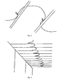
- Fig. 3A shows schematically an embodiment of the envelope to contain a bellows.
- the top horizontal line indicates the flat roof foil.
- a flat foil strip is indicated by the bottom line, both edges of which are sealed to the roof foil. Between the edges the foil strip and roof foil do not adhere.
- Fig. 3B shows schematically the envelope of fig. 3A expanded and a bellows added. Inside the envelope the expanded bellows is illustrated, which causes the expansion of the envelope.
- the parts are drawn at a mutual distance for clarity, while in practice they will have mutual surface contact.
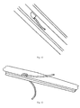
- Fig. 4 shows a picture taken inside the freight space, showing the upright side walls and the under side of the foil roof resting at the regular spaced cross rods.
- the black serpentine line is the air tube.
- a longitudinal extending bellows is absent.
- a cross bellows extends on top of each cross rod, such that the air tube is connected to a plurality of spaced air chambers of the bellows.
- the cross bellows are inflated, providing a gable top or triangle shape with highest point in line with the longitudinal centre line of the roof, such that the centre of the roof is highest lifted and inclines to each side while continuously supported along the length of each cross rod.
- the air tube is continuous along its length and has spaced air connections along its length.
- Each cross bellows is tightly fitting housed in an associated envelope.
- Fig. 5 shows how the roof is folded by shifting the cross rods, resting on top of the sides, towards each other, while the foil folds itself.
- Fig. 6 shows the partly folded open roof.
- Fig. 7 shows a detail of fig. 4 illustrating two successive cross rods and on top of each an envelope integrated with the roof foil. Also visible are the edges of the two foil strips, sealed to the roof foil, and a single hole in each envelope penetrated by an associated air connection of the bellows housed in the envelope.
- Fig. 8 is a view similar to fig. 7 .
- Fig. 9 is a view similar to fig. 4 , the only main difference being a different courseof the air tube.
- Fig. 10 shows a detail of fig. 9 .
- the gable top shape of the inflated cross bellows inside the envelopes on top of each cross rod is presented as the darker areas.
- Fig. 11 shows the embodiment of fig. 9 if the roof is collapsed by bringing the cross rods close to each other. The two air connections for each cross bellows are visible.
- Fig. 12 shows the roof of fig. 9 in a more collapsed condition compared to fig. 11 .
- Fig. 13 shows a detail of fig. 9 , the air connections have connection pipes extending parallel to the roof foil, such that the air tubes connect to the air connections in a parallel manner.
- Fig. 14 is similar to fig. 13 and gives a clear view of the envelope with cross bellows on top of the cross rod and the two air connections and part of the associated two length parts of the air tube. The sealed edges of the foil strip are also visible.
Landscapes
- Engineering & Computer Science (AREA)
- Mechanical Engineering (AREA)
- Tents Or Canopies (AREA)
- Forklifts And Lifting Vehicles (AREA)
Applications Claiming Priority (2)
| Application Number | Priority Date | Filing Date | Title |
|---|---|---|---|
| NL2005117 | 2010-07-20 | ||
| NL2005144 | 2010-07-23 |
Publications (2)
| Publication Number | Publication Date |
|---|---|
| EP2409869A2 true EP2409869A2 (de) | 2012-01-25 |
| EP2409869A3 EP2409869A3 (de) | 2015-04-01 |
Family
ID=44999658
Family Applications (1)
| Application Number | Title | Priority Date | Filing Date |
|---|---|---|---|
| EP11174767.1A Withdrawn EP2409869A3 (de) | 2010-07-20 | 2011-07-20 | Aufblasbarer Balg zum Anheben des flexiblen Daches eines LKW-Laderaumes |
Country Status (1)
| Country | Link |
|---|---|
| EP (1) | EP2409869A3 (de) |
Cited By (3)
| Publication number | Priority date | Publication date | Assignee | Title |
|---|---|---|---|---|
| DE202019100645U1 (de) | 2019-02-04 | 2019-02-08 | Bernhard Hünnekens | Aufblasbare Bedachung mit einem Dach mit einer flexiblen Dachhaut und einem aufblasbaren Stützelement |
| DE102019201386A1 (de) | 2019-02-04 | 2020-08-06 | Bernhard Hünnekens | Aufblasbare Bedachung mit einem Dach mit einer flexiblen Dachhaut und einem aufblasbaren Stützelement |
| FI20236286A1 (fi) * | 2023-11-20 | 2025-05-21 | Ukatan Trading Oy | Turvajärjestely ajoneuvon katetussa kuormatilassa ja kuormatilan suojapeite |
Citations (4)
| Publication number | Priority date | Publication date | Assignee | Title |
|---|---|---|---|---|
| SE468279B (sv) | 1991-11-04 | 1992-12-07 | Beco Produktutveckling Ab | Avisningsanordning foer fordon med oevertaeckt lastutrymme. |
| EP0897827A2 (de) | 1997-07-28 | 1999-02-24 | Holm Gellert | Vorrichtung zum Entfernen von Eis-, Schnee- und Wasseransammlungen auf Planen |
| WO1999049216A1 (en) | 1998-03-20 | 1999-09-30 | Piab Ab | Vacuum ejector pump |
| WO2005065975A1 (de) | 2004-01-09 | 2005-07-21 | Bauregger Guenter | Spann-hebeeinrichtung für ein fahrzeugplanenoberteil |
Family Cites Families (7)
| Publication number | Priority date | Publication date | Assignee | Title |
|---|---|---|---|---|
| DE3233672A1 (de) * | 1981-09-10 | 1983-04-07 | Georg 8027 Zürich Igloi | Plane an liefer- und last-autos |
| SE502642C2 (sv) * | 1994-02-19 | 1995-11-27 | Thorkild Baumbach | Avisningsanordning för motorfordon med övertäckt lastutrymme |
| DE29920069U1 (de) * | 1999-11-16 | 2001-03-29 | Claus, Achim, 27299 Langwedel | Enteisungsanlage für Kfz mit Aufbauten aller Art "Container, Planen, Koffer" |
| DE10224291A1 (de) * | 2002-05-31 | 2003-12-11 | K & M Stahl Behaelter | Vorrichtung zur Erhöhung der Verkehrssicherheit beplanter Fahrzeuge |
| CH705208B1 (de) * | 2002-06-25 | 2012-11-30 | Prospective Concepts Ag | Flächiges Gebilde mit einer fluidischen Spannvorrichtung. |
| US20100043913A1 (en) * | 2008-02-11 | 2010-02-25 | Zhino Salar Othman | Apparatus and method for ice and snow removal |
| DE202010001287U1 (de) * | 2010-01-25 | 2010-06-17 | Coatex N.V. | Vorrichtung zur Vermeidung von Schnee- und Eisplattenbildungen bei einem Verdeck aus Planen für ein Transportfahrzeug, wie Lastkraftwagen o.dgl. |
-
2011
- 2011-07-20 EP EP11174767.1A patent/EP2409869A3/de not_active Withdrawn
Patent Citations (4)
| Publication number | Priority date | Publication date | Assignee | Title |
|---|---|---|---|---|
| SE468279B (sv) | 1991-11-04 | 1992-12-07 | Beco Produktutveckling Ab | Avisningsanordning foer fordon med oevertaeckt lastutrymme. |
| EP0897827A2 (de) | 1997-07-28 | 1999-02-24 | Holm Gellert | Vorrichtung zum Entfernen von Eis-, Schnee- und Wasseransammlungen auf Planen |
| WO1999049216A1 (en) | 1998-03-20 | 1999-09-30 | Piab Ab | Vacuum ejector pump |
| WO2005065975A1 (de) | 2004-01-09 | 2005-07-21 | Bauregger Guenter | Spann-hebeeinrichtung für ein fahrzeugplanenoberteil |
Cited By (4)
| Publication number | Priority date | Publication date | Assignee | Title |
|---|---|---|---|---|
| DE202019100645U1 (de) | 2019-02-04 | 2019-02-08 | Bernhard Hünnekens | Aufblasbare Bedachung mit einem Dach mit einer flexiblen Dachhaut und einem aufblasbaren Stützelement |
| DE102019201386A1 (de) | 2019-02-04 | 2020-08-06 | Bernhard Hünnekens | Aufblasbare Bedachung mit einem Dach mit einer flexiblen Dachhaut und einem aufblasbaren Stützelement |
| DE102019201386B4 (de) * | 2019-02-04 | 2021-06-17 | Bernhard Hünnekens | Aufblasbare Bedachung mit einem Dach mit einer flexiblen Dachhaut und einem aufblasbaren Stützelement |
| FI20236286A1 (fi) * | 2023-11-20 | 2025-05-21 | Ukatan Trading Oy | Turvajärjestely ajoneuvon katetussa kuormatilassa ja kuormatilan suojapeite |
Also Published As
| Publication number | Publication date |
|---|---|
| EP2409869A3 (de) | 2015-04-01 |
Similar Documents
| Publication | Publication Date | Title |
|---|---|---|
| US20230264527A1 (en) | Self-reinflating tire | |
| US3693740A (en) | Load-carrying or lifting devices | |
| US20100200037A1 (en) | Flexible dual skin wall and device for tensioning a dual skin flexible wall | |
| US4979532A (en) | Jointing device for tents, covers etc. | |
| EP2409869A2 (de) | Aufblasbarer Balg zum Anheben des flexiblen Daches eines LKW-Laderaumes | |
| US9015998B2 (en) | Airbeam | |
| US9199790B2 (en) | Inflatable refuse containers and methods of use | |
| EP2409868A2 (de) | Luftrohr für eine Vorrichtung zum Anheben des flexiblen Dachs des LKW-Laderaums mittels Aufblasen eines Balgs | |
| US8215615B2 (en) | Wedge-formed lifting cushion | |
| CN108560717B (zh) | 一种气承式多层膜建筑结构 | |
| EP0097051A1 (de) | Blende | |
| CN206158538U (zh) | 一种车库防水结构及调度结构 | |
| JPH10512520A (ja) | 気球用バスケット | |
| SE502642C2 (sv) | Avisningsanordning för motorfordon med övertäckt lastutrymme | |
| CN113931165B (zh) | 一种软土地基真空预压施工结构及施工方法 | |
| CN119022136A (zh) | 一种用于密封地下室侧墙与管道间隙的封堵护管件 | |
| CN108060827B (zh) | 用于高压帐篷气柱支撑系统 | |
| EP0270367A2 (de) | Aufblasbare dehnbare Vorrichtung | |
| US6586062B1 (en) | Device for rolling out on the floor a rolled stored temporary surface covering | |
| EP2658760A1 (de) | Durch luft aufgeblasene vorrichtung für planen zum entfernen von eis usw. | |
| JP3891521B2 (ja) | 膨脹式屋根 | |
| GB2275893A (en) | Oil containment boom. | |
| JPH10331489A (ja) | 空気膜構造体 | |
| JPH0411054Y2 (de) | ||
| JPH09151604A (ja) | コンクリート用型枠 |
Legal Events
| Date | Code | Title | Description |
|---|---|---|---|
| AK | Designated contracting states |
Kind code of ref document: A2 Designated state(s): AL AT BE BG CH CY CZ DE DK EE ES FI FR GB GR HR HU IE IS IT LI LT LU LV MC MK MT NL NO PL PT RO RS SE SI SK SM TR |
|
| AX | Request for extension of the european patent |
Extension state: BA ME |
|
| PUAI | Public reference made under article 153(3) epc to a published international application that has entered the european phase |
Free format text: ORIGINAL CODE: 0009012 |
|
| PUAL | Search report despatched |
Free format text: ORIGINAL CODE: 0009013 |
|
| AK | Designated contracting states |
Kind code of ref document: A3 Designated state(s): AL AT BE BG CH CY CZ DE DK EE ES FI FR GB GR HR HU IE IS IT LI LT LU LV MC MK MT NL NO PL PT RO RS SE SI SK SM TR |
|
| AX | Request for extension of the european patent |
Extension state: BA ME |
|
| RIC1 | Information provided on ipc code assigned before grant |
Ipc: B60J 7/10 20060101AFI20150224BHEP Ipc: B60J 7/12 20060101ALI20150224BHEP Ipc: B60J 7/00 20060101ALI20150224BHEP |
|
| STAA | Information on the status of an ep patent application or granted ep patent |
Free format text: STATUS: THE APPLICATION IS DEEMED TO BE WITHDRAWN |
|
| 18D | Application deemed to be withdrawn |
Effective date: 20151002 |