EP2409887A2 - Procédé et système de régulation de la tenue de route d'un véhicule utilitaire - Google Patents
Procédé et système de régulation de la tenue de route d'un véhicule utilitaire Download PDFInfo
- Publication number
- EP2409887A2 EP2409887A2 EP11174176A EP11174176A EP2409887A2 EP 2409887 A2 EP2409887 A2 EP 2409887A2 EP 11174176 A EP11174176 A EP 11174176A EP 11174176 A EP11174176 A EP 11174176A EP 2409887 A2 EP2409887 A2 EP 2409887A2
- Authority
- EP
- European Patent Office
- Prior art keywords
- zul
- truck
- calculation unit
- sensor
- path curvature
- Prior art date
- Legal status (The legal status is an assumption and is not a legal conclusion. Google has not performed a legal analysis and makes no representation as to the accuracy of the status listed.)
- Withdrawn
Links
- 238000000034 method Methods 0.000 title claims abstract description 30
- 230000001105 regulatory effect Effects 0.000 title 1
- 230000008859 change Effects 0.000 claims abstract description 84
- 230000002123 temporal effect Effects 0.000 claims abstract description 47
- 238000012544 monitoring process Methods 0.000 claims abstract description 24
- 230000001133 acceleration Effects 0.000 claims description 39
- 230000005484 gravity Effects 0.000 claims description 14
- 238000004891 communication Methods 0.000 claims description 10
- 230000010355 oscillation Effects 0.000 claims description 6
- 230000010363 phase shift Effects 0.000 claims description 3
- 230000005540 biological transmission Effects 0.000 claims 1
- 230000001419 dependent effect Effects 0.000 claims 1
- 230000000737 periodic effect Effects 0.000 claims 1
- 230000006870 function Effects 0.000 description 26
- 230000033001 locomotion Effects 0.000 description 11
- 238000005259 measurement Methods 0.000 description 3
- 230000003068 static effect Effects 0.000 description 3
- 239000000969 carrier Substances 0.000 description 2
- 238000013461 design Methods 0.000 description 2
- 238000010586 diagram Methods 0.000 description 2
- 230000000694 effects Effects 0.000 description 2
- 230000008569 process Effects 0.000 description 2
- 238000012545 processing Methods 0.000 description 2
- 238000005096 rolling process Methods 0.000 description 2
- 230000009471 action Effects 0.000 description 1
- 230000006978 adaptation Effects 0.000 description 1
- 230000033228 biological regulation Effects 0.000 description 1
- 150000001875 compounds Chemical class 0.000 description 1
- 230000006378 damage Effects 0.000 description 1
- 238000011161 development Methods 0.000 description 1
- 230000005284 excitation Effects 0.000 description 1
- 230000002349 favourable effect Effects 0.000 description 1
- 238000001914 filtration Methods 0.000 description 1
- 230000001788 irregular Effects 0.000 description 1
- 238000003825 pressing Methods 0.000 description 1
- 230000002265 prevention Effects 0.000 description 1
- 230000006641 stabilisation Effects 0.000 description 1
- 238000011105 stabilization Methods 0.000 description 1
- 230000000087 stabilizing effect Effects 0.000 description 1
- 230000001360 synchronised effect Effects 0.000 description 1
Images


Classifications
-
- B—PERFORMING OPERATIONS; TRANSPORTING
- B60—VEHICLES IN GENERAL
- B60T—VEHICLE BRAKE CONTROL SYSTEMS OR PARTS THEREOF; BRAKE CONTROL SYSTEMS OR PARTS THEREOF, IN GENERAL; ARRANGEMENT OF BRAKING ELEMENTS ON VEHICLES IN GENERAL; PORTABLE DEVICES FOR PREVENTING UNWANTED MOVEMENT OF VEHICLES; VEHICLE MODIFICATIONS TO FACILITATE COOLING OF BRAKES
- B60T8/00—Arrangements for adjusting wheel-braking force to meet varying vehicular or ground-surface conditions, e.g. limiting or varying distribution of braking force
- B60T8/17—Using electrical or electronic regulation means to control braking
- B60T8/1755—Brake regulation specially adapted to control the stability of the vehicle, e.g. taking into account yaw rate or transverse acceleration in a curve
-
- B—PERFORMING OPERATIONS; TRANSPORTING
- B66—HOISTING; LIFTING; HAULING
- B66C—CRANES; LOAD-ENGAGING ELEMENTS OR DEVICES FOR CRANES, CAPSTANS, WINCHES, OR TACKLES
- B66C15/00—Safety gear
- B66C15/06—Arrangements or use of warning devices
- B66C15/065—Arrangements or use of warning devices electrical
-
- B—PERFORMING OPERATIONS; TRANSPORTING
- B66—HOISTING; LIFTING; HAULING
- B66C—CRANES; LOAD-ENGAGING ELEMENTS OR DEVICES FOR CRANES, CAPSTANS, WINCHES, OR TACKLES
- B66C19/00—Cranes comprising trolleys or crabs running on fixed or movable bridges or gantries
- B66C19/007—Cranes comprising trolleys or crabs running on fixed or movable bridges or gantries for containers
Definitions
- the invention relates to a method and a system for controlling the driving behavior of a truck, in particular a portal stacker or other mobile machine with an unfavorable ratio of center of gravity and track.
- a statically stable state is reached when, in a stationary, ie constant driving condition of the truck acting on this stationary torque is greater than a corresponding overturning moment.
- the stall torque of the truck results from the total weight, ie a sum of curb weight and lifted load (payload), multiplied by an effective, horizontal lever arm from a forklift center of gravity in which the total weight acts, to a tilting edge.
- the tilting edge is an imaginary line on a floor about which the stacker tilts, the line being arranged, on the one hand, perpendicular to a sum vector of the tilting forces and, on the other hand, perpendicular to a plane in which the stacker turns on tilting.
- tilting moment Under the tilting moment one understands the sum of all mass forces acting on the parts of the truck and the payload multiplied by their vertical distances of the points of attack to a tilting edge of the truck.
- tilting in a transverse direction ie can take place about the longitudinal axis of the truck.
- Such tilting about the longitudinal axis is also referred to as rolling.
- braking or acceleration ie a change in the travel speed in time, can lead to tilting in the longitudinal direction, that is to say about a transverse axis of the industrial truck. Tilting about the transverse axis is also referred to as pitching.
- This object is achieved by a method having the features specified in claim 1.
- a method for controlling a driving behavior of an industrial truck in particular a gantry forklift or another mobile working machine with an unfavorable ratio of center of gravity and track width, is suitable for avoiding vibration-generating movements.
- the ratio of the center of gravity and the gauge is all the less favorable, the higher the center of gravity and the smaller the gauge.
- the determination of a travel speed of the truck with at least one vehicle speed sensor, a path curvature along which the truck travels, with at least one Brubümmungssensor, a weight of the truck raised load, for example in the form of a container, with at least one weight sensor and a lifting height of the load with at least one lifting height sensor.
- the driving speed can also be determined quickly and unambiguously, for example, from a measured rotational speed of a traction motor.
- Additional sensors the truck in order to control the driving behavior according to the invention, do not have. However, such additional sensors can be used depending on the design of the truck.
- a steering state calculation unit which can be used in carrying out the method according to the invention, but does not necessarily have to be used, a steering state and / or a change over time of the steering state of the truck depending on the vehicle speed and the curvature of the rail are calculated.
- the steering state refers to the current state of the truck, described by the instantaneous values of driving speed and curvature of the track.
- the steering state is in the transverse direction, ie transverse to the direction of the truck, a centrifugal acceleration of the truck (product of the squared speed with the curvature of the web) and in the longitudinal direction, ie in the direction of the truck acceleration as a change in the magnitude of the speed vector a driving speed of the truck specified.
- the term "steering state” is used below, this means a steering state quantity in units of the acceleration.
- the permissible steering state is generally understood to be a permissible, statically stable condition of the industrial truck, which is described by the travel speed and the path curvature along which the industrial truck travels.
- the centrifugal acceleration can be used on the truck.
- a load state calculation unit the calculation of a load condition of the truck takes place as a function of the weight and the lifting height of the load.
- the load condition can therefore be described by the instantaneous values of payload and lifting height.
- a reference mass of the truck is determined as a function of the weight of the load, which may be, for example, the sum of a known curb weight of the truck and the weight of the load. It is also possible that the reference mass comprises only the weight of the load or the sum of the weight of the load and the weight of one or more components of the truck.
- a tolerance range calculation unit calculates an allowable tolerance range for the path curvature and / or its time change and for the travel speed and / or its time change.
- the tolerance range for the path curvature and / or their temporal change serve to prevent oscillation in the transverse direction, ie the roll about the longitudinal axis of the truck. As a result, the risk of tipping is reduced from a yz plane of the truck.
- the path curvature is here representative of any measurand with which a steering or curve condition of the truck can be detected.
- a tolerance range for the steering state or a tolerance range for a steering angle can also be specified as an alternative to a tolerance range for the path curvature. Accordingly, the driving speed and / or its temporal change serve to prevent swinging in the longitudinal direction, ie pitching about the transverse axis of the truck. Accordingly, the risk of tipping is reduced from an xz plane of the truck.
- a monitoring of the path curvature and / or its change over time as well as the driving speed and / or its temporal change takes place with a monitoring unit.
- a control unit ensures that the path curvature and / or its change over time as well as the driving speed and / or its temporal change are within the permissible tolerance range. This means that, for example, in the case of an unreasonable action of a driver which causes a change in the path curvature and / or its change in time and the travel speed and / or their temporal change such that the monitored characteristics describing the path curvature are actively limited, if they would leave the permissible tolerance range.
- the driver can not therefore choose any path curvature, for example in the form of any steering angle or a particularly fast steering angle change.
- the path curvature Upon reaching a maximum value for the path curvature or its time change, this is limited.
- the temporal change of the path curvature can be limited, whereby upon reaching a limit of the tolerance range for the permissible path curvature, the permissible change thereof is equal to zero, so that the path curvature does not change itself.
- the path curvature itself can be limited by limiting the temporal change of the path curvature. Accordingly, the further parameters such as driving speed and / or temporal change of the driving speed are monitored and compliance with the permissible tolerance range is ensured.
- the inventive method may include calculating a steering state and / or a temporal change of Steering state of the truck depending on the vehicle speed and the curvature of the railway, carried out with a steering state calculation unit include.
- the determination of the path curvature is simplified because steering angle sensors are usually present on an industrial truck and in particular on a gantry forklift, so that no additional sensors need to be retrofitted to carry out the method.
- a steering angle and / or its temporal change are determined. It is also possible for the time change of the steering angle from the measured steering angle to take place with a separate calculation unit.
- the steering angle is approximately equal to or proportional to the path curvature or the arc tangent of the path curvature. This means that the path curvature can be determined indirectly by determining the steering angle.
- a method according to claim 3 serves to further increase the safety of the truck against tilting about the longitudinal axis and / or about the transverse axis.
- a method according to claim 4 ensures a safe handling of the truck with a necessary, active adjustment of-Brukurfahrung, driving speed and / or their changes over time with the control unit by preventing the truck from swinging.
- the driving behavior and a possibly occurring vibration of the truck can be mapped with a model of a single-mass oscillator in a good approximation.
- the reference mass of the truck and the load condition characterizing Einmasseschwinger own angular frequency of the structure of the truck are used as characteristics, the natural angular frequency is determined as a characteristic characteristic of the structure.
- the structure includes, for example, vehicle carriers, wheels, machine platform, supports, grippers and cab of the truck as well as the payload in the form of the container.
- the structure may have additional or less than the aforementioned components.
- other sizes can be incorporated, for example, a lifting height of the load or a driving speed of the truck.
- a method according to claim 5 allows a direct and effective prevention of vibration excitation of the truck.
- a method according to claim 6 allows a direct and quick calculation of an upper limit of the allowable tolerance range in the form of a maximum permissible change in the time of the steering state. This ensures that a changing tolerance range can be updated quickly. This is an important prerequisite for a delay-free functioning of the control of the driving state. As a result, the safety against tipping of the truck is additionally increased.
- the period of oscillation used in this embodiment of the method is the oscillation period of an oscillation having the natural angular frequency.
- a system for controlling a driving behavior of an industrial truck in particular a portal stacker or other mobile machine with an unfavorable ratio of center of gravity to track by avoiding vibrations of the truck, that supervised, the driving characteristics of the truck characterizing sizes are within a specified permissible tolerance range.
- the variables mentioned are the curvature of the track and / or its change over time as well as the driving speed and / or its change over time.
- the steering state already defined above and / or its temporal change can also be used as the variable characterizing the driving behavior of the industrial truck. As a result, it can be avoided that the truck is caused to vibrate-generating movements as a result of a driver's driving error.
- the system according to the invention comprises at least one vehicle speed sensor for determining the driving speed of the industrial truck, at least one path curvature sensor for determining a path curvature along which the industrial truck travels, at least one weight sensor and at least one lifting height sensor for determining a weight and a Lifting height of a load lifted by the truck. Furthermore, a steering state calculation unit for calculating a steering state and / or a temporal change of the steering state of the industrial truck in dependence on the vehicle speed and the curvature and a load state calculation unit for calculating a load condition of the truck depending on the weight and the lifting height can be provided.
- a tolerance calculation unit is used to calculate a permissible tolerance range for the path curvature and / or its change over time and for the travel speed and / or its temporal change as a function of the load condition and a reference mass of the truck determined as a function of the weight of the load.
- a monitoring unit monitors the path curvature and / or its change over time as well as the travel speed and / or its temporal change, wherein a control unit ensures that the aforementioned variables do not leave the permissible tolerance range.
- the at least one vehicle speed sensor and the at least one path curvature sensor may be connected to the steering state calculation unit for transmitting the determined characteristic values. The determined characteristic values serve as input data for the tolerance range calculation.
- the at least one weight sensor and the at least one lift height sensor are connected to the load state calculation unit for transmitting the determined characteristic values as input data for the load state calculation.
- the load state calculation unit is connected to the tolerance calculation unit, so that the characteristic values calculated with the load state calculation unit can be transmitted as input data for calculating the allowable tolerance range.
- the permissible tolerance range calculated with the tolerance calculation unit is used as an input data record for monitoring the corresponding data in signal communication with the tolerance calculation unit Transmitted monitoring units. Accordingly, the monitoring unit is in signal communication with the control unit for ensuring compliance with the allowable tolerance range.
- the system according to the invention can have a steering state calculation unit for calculating a steering state and / or a temporal change of the steering state of the industrial truck as a function of the travel speed and of the path curvature.
- the at least one vehicle speed sensor and the at least one path curvature sensor may be in signal communication with the optionally provided steering state calculation unit for transmitting the corresponding sensor or characteristic values as input data for a steering state calculation.
- a system according to claim 8 simplifies the determination of relevant variables necessary for the calculation of the permissible tolerance range.
- a system according to claim 9 is compact and has an integrative structure.
- a system with a control unit according to claim 10 has proved to be particularly advantageous.
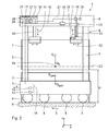
- FIG. 1 and 2 An in Fig. 1 and 2 purely schematically illustrated truck in the form of a portal stacker 1 is used for transporting and stacking loads in the form of containers 2.
- the stacker 1 has two spaced and parallel to each other Fahrough 3, each receiving a plurality of wheels 4 for moving the stacker 1.
- the wheels 4 are independent of each other and may in particular each have their own drive.
- the steering of the wheels 4 is synchronized; This can be realized, for example, in the form of one-axle, Zweiachs- or Mehrachslenk Institute.
- the wheels 4 of a driving carrier 3 are predetermined by this in the direction of travel 5 and arranged one behind the other.
- the direction of travel 5 also corresponds to the longitudinal direction of the stacker 1, to which a longitudinal axis 23 is arranged in parallel. Accordingly, a transverse axis 24 is oriented perpendicular to the longitudinal axis 23 and thus also to the direction of travel 5 and defines the transverse direction of the stacker 1.
- the axes 23, 24 are also referred to as the x-axis or y-axis of a Cartesian coordinate system. Accordingly, the Level of the bottom 6, on which the stacker 1 moves, oriented parallel to the xy plane.
- the carriers 3 are supported by the wheels 4 with respect to a bottom 6 and arranged substantially parallel to the bottom 6. Perpendicular from drivers 3 upwards, d. H. facing away from the bottom 6, each extending two supports 7, which form a portal 9 with an overlying, the supports 7 of the two carriages 3 interconnecting machine platform 8.
- the portal 9 is designed such that the portal stacker 1 can drive over at least one and in particular three or four stacked containers 2 without collision.
- the portal stacker 1 has a central vertical axis 21 or z-axis.
- the portal stacker 1 is designed to be doubly symmetrical, in particular with respect to its geometry, ie the portal stacker 1 is in accordance with the front view in FIG Fig. 1 and according to the side view in FIG Fig. 2 each designed geometrically axisymmetric to the vertical axis 21.
- the distribution of the masses of the stacker 1 can also take place asymmetrically with respect to the vertical axis 21, so that, for example, a total center of gravity S tot of the portal stacker 1 can be arranged at a distance from the vertical axis.
- tilting of the portal stacker 1 from the yz plane, ie, a rotation about the longitudinal axis 23 is possible by the stacker 1 with respect to the vertical axis 21 via one of the two driving carrier 3 to the side.
- Such an oscillating movement about the longitudinal axis 23 is also referred to as rolling.
- the portal stacker 1, in particular in an uphill or downhill and / or in a strong braking or acceleration process rotates about the transverse axis 24 and thus tilts forward or backward.
- a such oscillating motion about the transverse axis 24 is also referred to as pitching.
- the grippers 10 are designed to receive the container 2 accordingly.
- the grippers 10 are preferably designed as standardized, known load-receiving means, which engage in corresponding holding means of the container 2.
- load handling devices are known in practice as spreaders with twistlocks.
- the grippers 10 may also be designed as telescopic pliers and moved apart or together along an opening or closing direction 22 for releasing or gripping the container 2.
- a vehicle speed sensor 13 for determining the vehicle speed v of the portal stacker 1 is provided. It is also possible to provide fewer vehicle speed sensors 13, but at least one. In the case of several sensors, for example, the driving speeds v i of individual wheels 4 are determined and from this an average value of the driving speed v m of the portal stacker 1 is calculated.
- at least a path curvature sensor in the form of a steering angle sensor 14 is provided in the carrier 3, wherein the steering angle sensor 14 for determining a current actual steering angle ⁇ is the wheels 4 and / or a time change of the steering angle d ⁇ is / dt is used.
- a path curvature ⁇ of a path along which the stacker 1 travels can be determined, where, for example, ⁇ ⁇ ⁇ or ⁇ ⁇ tan ( ⁇ ).
- the gripper 10 is height adjustable via a driven by a lifting motor 25 winch 26.
- a weight sensor 15 for determining the weight G L of the container 2 raised by the stacker 1, that is to say the payload, is attached directly to the gripper 10 according to the exemplary embodiment shown. It is also possible for the weight sensor 15 to be provided directly on the portal 9 or at another location within a force flow occurring due to the lifting of the container 2. It is also possible to provide a plurality of weight sensors 15.
- the weight G L of the container 2 engages in the center of gravity S L of the container 2.
- the weight sensor 15 can be designed, for example, in the form of a torque sensor for determining a torque of a lifting motor for lifting the container 2.
- a lifting height sensor 16 serves to determine the lifting height H of the container 2 and is provided on the lifting motor 25 and on the winch 26. It is also possible to use more than one lift height sensor 16.
- a mass calculation unit 27 is accommodated in a control cabinet 28 on the machine platform 8 or at another location.
- the reference mass m B of the stacker 1 is calculated from the sum of the weight G L of the container 2 and an empty weight G 0 of the unloaded stacker 1.
- additional weights for example caused by components additionally mounted on the stacker 1, can be taken into account Find.
- the reference mass m B engages in the overall center of gravity S ges to the stacker. 1 Accordingly, the mass calculation unit 27 is in signal connection with the weight sensor 15.
- a tolerance range calculation unit 17 for calculating a permissible tolerance range for the path curvature ⁇ and / or their temporal change dp / dt or for calculating a permissible tolerance range for a steering state a and / or its temporal change da / dt and for calculating a permissible tolerance range for the driving speed v and / or their temporal change dv / dt in dependence on the determined variables is arranged in the control cabinet 28.
- an angular frequency ⁇ of a vibration system corresponding to a first natural frequency can be used for vibrations in the longitudinal direction or in the transverse direction.
- the structure of the truck 1 includes the Fahrlich 3, the wheels 4, the machine platform 8, the supports 7, the gripper 10 and the driver's cab, not shown, and held with the grippers 10 container 2.
- the vibration system can as Single oscillator with the mass m B and the angular frequency ⁇ , possibly including further, the truck 1 characterizing sizes are displayed.
- a load state calculation unit 29 arranged in the control cabinet 28 is used, which is in signal connection with the weight sensor 15 and with the lift height sensor 16.
- the angular frequency is determined as a function of the lifting height H and the weight G L.
- the load state calculation unit 29 is in signal communication with the tolerance calculation unit 17 for transmitting the angular frequency ⁇ .
- a steering state calculation unit 30 for calculating a steering state a and / or a temporal change of the steering state da / dt of the stacker 1 as a function of the vehicle speed v and the path curvature ⁇ is provided in the control cabinet 28.
- the steering state calculation unit 30 is connected to the path curvature sensor and in particular to the steering angle sensor 14, and furthermore to the vehicle speed sensor 13.
- a likewise arranged in the cabinet 28, with the tolerance calculation unit 17 in signal communication standing monitoring unit 31 is provided for monitoring the path curvature ⁇ and their temporal change dp / dt or the steering state a and / or its temporal change da / dt and the driving speed v and / or whose temporal change dv / dt is used.
- the monitoring unit 31 monitors the path curvature ⁇ and the travel speed v as well as their time derivatives, it is possible to look at an interposed steering state calculation and consequently also be dispensed with the steering state calculation unit 30.
- the data of the vehicle speed sensor 13 and the steering angle sensor 14 are then transmitted directly to the monitoring unit 31.
- the monitoring unit 31 is connected to a control unit 32 to ensure compliance with the allowable tolerance range.
- the control unit 32 is likewise arranged in the control cabinet 28.
- the control unit 32 is directly connected to the calculation units 17, 27, 29, 30. It is also possible to combine the calculation units 17, 27, 29, 30 into a single calculation unit and, in particular, to integrate it into the control unit 32. Accordingly, the mass calculation unit 27 may also be integrated in the load state calculation unit 29.
- All signal connections of the stacker 1 are designed as data lines 18. It is also possible that the signal connections are wireless, for example by means of radio.
- a lateral acceleration a occurring due to cornering may be used as a centrifugal acceleration.
- the control unit 32 has a PID controller. As a result, a particularly fast, effective control of the driving condition is achieved.
- sensors may be provided, for example, the deflection of at least one wheel 4 of the portal stacker 1, the acceleration of the truck 1, the inclination angle of the stacker. 1 towards the ground 6 and the driving force of a wheel 4 for further consideration for the stabilization of the steering state available.
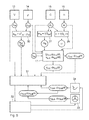
- the following is a method for controlling the driving behavior of the portal stacker 1 using the example of a movement in the yz plane, for example in the form of an inclination about the longitudinal axis 23 with reference to the in Fig. 5 Schematically illustrated schematic diagram described.
- the current travel speed v ist of the stacker 1 with the vehicle speed sensor 13 and the path curvature ⁇ is a path along which the stacker 1 travels, determined with the path curvature sensor in the form of the steering angle sensor 14 and transmitted to the steering state calculation unit 30.
- the determination of the path curvature is ⁇ via the steering angle ⁇ is proportional to ⁇ path curvature or their arctangent tan ( ⁇ 's) is.
- the calculation of the steering state characterizing a centrifugal acceleration is performed and / or because its temporal change is / dt. Furthermore, the weight G L of the load 2 lifted by the stacker 1 with the weight sensor 15 and the lift height H of the load 2 with the lift height sensor 16 are determined and transmitted to the load state calculation unit 29. There, the calculation of the load condition characterizing angular frequency ⁇ in dependence on the weight G L and the lifting height H.
- the angular frequency ⁇ describes a first natural frequency of the structure as a vibration system for modeling the truck 1 as a compound oscillator with the reference ground m B and the angular frequency ⁇ serves. According to this modeling, the centrifugal acceleration a is a function of the time a (t).
- the dependence on the time t of the centrifugal acceleration a (t) is due to a symmetrical sinusoid without phase shift in Fig. 3 shown schematically.
- the maximum amplitude a max of the centrifugal acceleration is in Fig. 3 specified.
- This maximum amplitude a , max corresponds to a statically stable state, ie a state in which a quotient of stationary and tilting moments acting on the portal stackers during stationary movement is greater than 1, so that tilting occurs when the maximum amplitude a max of the centrifugal acceleration is present is safely prevented.
- This maximum amplitude a max of the centrifugal acceleration can be used as a permissible acceleration-related acceleration a zul for a stationary driving state or for a static equilibrium of the stacker 1.
- the reference mass m B of the stacker 1 required for the modeling is determined as a function of the weight G L of the container 2.
- d dt ⁇ v 1 2 ⁇ a ⁇ ⁇ d dt ⁇ a for the permissible change of the driving speed in relation to the transverse direction.
- the tolerance range for the permissible change over time of the driving speed can be limited due to the permissible acceleration in the longitudinal direction, ie in the direction of travel of the stacker 1 or due to the permissible acceleration in the transverse direction, as far as the truck 1 makes a turn.
- Decisive here is which admissibility value is reached for which of the variables ⁇ or v earlier.
- d dt ⁇ ⁇ ⁇ ⁇ zul ⁇ ⁇ ⁇ cos arcsin ⁇ ⁇ zul or d dt ⁇ ⁇ d dt ⁇ a v 2 ,
- the tolerance limit ⁇ zul for the path curvature is a function of the travel speed, the payload G L and the lift height H.
- the tolerance limit for the change in the time of the path curvature is a function of the vehicle speed, the payload, the lifting height, the natural angular frequency and the current curvature of the track.
- the tolerance limit v zul for the travel speed is a function of the payload, the lift height and the current path curvature.
- the tolerance limit for the change over time of the driving speed is a function on the one hand of the payload and the lifting height, which concerns the acceleration along the direction of travel and on the other hand, a function of the current speed and the curvature of the path in the direction transverse to the direction of travel.
- the tolerance range calculation unit 17 may also be an allowable tolerance range for the allowable centrifugal acceleration, so the steering state a perm, and / or the permissible time change since perm / dt to calculate.
- the permissible temporal change da zul / dt applies as upper limit: d dt ⁇ a ⁇ a zul ⁇ ⁇ ⁇ cos arcsin ⁇ a zul ,
- the tolerance calculation unit 17 can calculate a tolerance range for the permissible steering angle ⁇ zul as well as its permissible temporal change d ⁇ zul / dt.
- the permissible values calculated by the tolerance calculation unit 17 are transmitted to the monitoring unit 31.
- the current actual values of the steering state are determined, from which the centrifugal acceleration is a and / or whose temporal change is there / dt calculated and transmitted to the monitoring unit 31 and monitored by this.
- a target steering angle ⁇ target and its change in time d ⁇ set / dt are specified as desired values for a steering angle ⁇ to be set.
- the driver By pressing an accelerator pedal 34, the driver continues to set desired values for the vehicle speed v setpoint as well as their time change dv setpoint / dt. From the setpoint speed values v setpoint and dv setpoint / dt and the setpoint values for the path curvature ⁇ calculated from the steering angle ⁇ , setpoint values for the steering state a setpoint and its time change da setpoint / dt are calculated and sent to the monitoring unit for monitoring 31 transmitted.
- the control unit 32 ensures that the monitored values a, da / dt, are a target and as target / dt within the calculated additional tolerance range.
- control unit 32 In the event that the monitored values reach the limits of the permissible tolerance range as a result of a steering movement, an active control is carried out with the control unit 32 in such a way that an exceeding of the permissible values for the centrifugal acceleration a zul and / or its temporal change is permissible is prevented.
- control unit 32 is in signal communication both with the steering wheel 33 and with the accelerator pedal 34, so that actuation of the same upon reaching the calculated, allowable values a Soll , da Soll / dt, v set and / or dv set / dt limited is.
- vibration-generating movements are avoided and thus the driving safety of the truck 1 is increased, ie the risk of tipping is correspondingly reduced.
- a time axis of sine functions according to 3 and 4 runs along.
- the truck 1 at a constant speed v is traveling on a track with a constant path radius ⁇
- acted upon by the centrifugal acceleration a is, as long as the truck 1 retains this radius and this speed.
- the timeline after the 3 and 4 is therefore not the real time axis, but corresponds to the development of the argument of the sine or cosine function and is still used as a parameter.
- the centrifugal acceleration a (t) can, according to the embodiment shown in FIG Fig.
- the allowable value of the time change of the centrifugal acceleration da zul / dt from the first derivative after the time t of the centrifugal acceleration a is determined as follows:
- the first derivative after the time da (t) / dt of the centrifugal acceleration a (t) is in Fig. 4 shown.
- the illustrated Function corresponds to a harmonic cosine function without phase shift.
- the sine function a (t) has the natural angular frequency ⁇ and a maximum amplitude a max .
- the permissible value of the time derivative of the centrifugal acceleration da zul / dt is determined such that within the first quarter of the period of the function of the centrifugal acceleration a (t) that time t 0 is determined, at which the function of the centrifugal acceleration a (t) a current Actual value a is the centrifugal acceleration assumes. At this time t 0 will be used according to the in Fig. 4 shown derivative function of the centrifugal acceleration of the maximum permissible value da zul / dt directly determined.
- the calculated, permissible tolerance range can be stored in the monitoring unit 31 in addition to the above-described functional dependency also in tabular form for numerous, possibly standard driving speeds v and load states a and their time changes. It is also possible to equip the tolerance range calculation unit 17 with a wired and, in particular, wireless interface such that updating of the permissible tolerance range is subsequently facilitated if, for example, novel steering states a or vehicle speeds v are deemed to be relevant and should accordingly be stored.
- the permissible steering state a zul will be the smaller, the larger the reference mass m B and the smaller the load state ⁇ .
- the driving behavior characterizing actual values such as Actual centrifugal acceleration a and / or their changes in time as is / dt and the actual vehicle speed v and the time change dv / dt
- the actual path curvature ⁇ and / or its temporal change is d ⁇ / dt
- the actual Steering angle is ⁇
- its temporal change d ⁇ is / dt at regular intervals and in particular continuously detected and transmitted to the tolerance range calculation unit 17 for comparison with the allowable tolerance range.
- the actual values are within the permissible tolerance range, there is no active adaptation of the driving behavior by the control unit 32.
Landscapes
- Engineering & Computer Science (AREA)
- Mechanical Engineering (AREA)
- Transportation (AREA)
- Forklifts And Lifting Vehicles (AREA)
Applications Claiming Priority (1)
| Application Number | Priority Date | Filing Date | Title |
|---|---|---|---|
| DE201010031531 DE102010031531A1 (de) | 2010-07-19 | 2010-07-19 | Verfahren und System zur Regelung eines Fahrverhaltens eines Flurförderzeugs |
Publications (2)
| Publication Number | Publication Date |
|---|---|
| EP2409887A2 true EP2409887A2 (fr) | 2012-01-25 |
| EP2409887A3 EP2409887A3 (fr) | 2013-08-28 |
Family
ID=44785177
Family Applications (1)
| Application Number | Title | Priority Date | Filing Date |
|---|---|---|---|
| EP11174176.5A Withdrawn EP2409887A3 (fr) | 2010-07-19 | 2011-07-15 | Procédé et système de régulation de la tenue de route d'un véhicule utilitaire |
Country Status (2)
| Country | Link |
|---|---|
| EP (1) | EP2409887A3 (fr) |
| DE (1) | DE102010031531A1 (fr) |
Cited By (2)
| Publication number | Priority date | Publication date | Assignee | Title |
|---|---|---|---|---|
| US11352243B2 (en) | 2018-09-13 | 2022-06-07 | Crown Equipment Corporation | System and method for controlling a maximum vehicle speed for an industrial vehicle based on a calculated load |
| CN115544657A (zh) * | 2022-09-30 | 2022-12-30 | 徐工消防安全装备有限公司 | 车辆稳定性计算方法 |
Families Citing this family (1)
| Publication number | Priority date | Publication date | Assignee | Title |
|---|---|---|---|---|
| DE102015118472A1 (de) * | 2015-10-29 | 2017-05-04 | Jungheinrich Aktiengesellschaft | Flurförderzeug mit einem Lastteil und einem Antriebsteil |
Citations (1)
| Publication number | Priority date | Publication date | Assignee | Title |
|---|---|---|---|---|
| WO2002051680A1 (fr) | 2000-12-23 | 2002-07-04 | Robert Bosch Gmbh | Procede et dispositif pour stabiliser un vehicule |
Family Cites Families (11)
| Publication number | Priority date | Publication date | Assignee | Title |
|---|---|---|---|---|
| DE3122720C1 (de) * | 1981-06-06 | 1983-01-13 | Jungheinrich Unternehmensverwaltung Kg, 2000 Hamburg | "Verfahren zur Bremsung eines Stapelfahrzeugs mit ausfahrbarem Lastträger und Hubgerüst und Stapelfahrzeug, insbesondere Hochregalstapler, zur Durchführung des Verfahrens" |
| JPS58152793A (ja) * | 1982-03-05 | 1983-09-10 | ティー・シー・エム株式会社 | 運搬車両の横転防止装置 |
| DE19918597C2 (de) * | 1999-04-23 | 2001-03-08 | Deutsch Zentr Luft & Raumfahrt | Verfahren zur Reduktion der Kippgefahr von Straßenfahrzeugen |
| US6324446B1 (en) * | 1999-12-21 | 2001-11-27 | Ford Global Technologies, Inc. | Roll over stability control for an automotive vehicle |
| DE10154805A1 (de) * | 2001-11-08 | 2003-05-28 | Linde Ag | Flurförderzeug mit einer Stabilisierungseinrichtung zur Erhöhung der seitlichen Kippstabilität |
| DE10245462A1 (de) * | 2002-02-06 | 2003-08-14 | Gunnar Maas | Sicherheitssystem für Flurförderzeuge mit aufsitzendem Arbeitnehmer (Gabelstapler) |
| DE102005012004B4 (de) * | 2004-04-07 | 2020-09-24 | Linde Material Handling Gmbh | Flurförderzeug mit erhöhter statischer/quasistatischer und dynamischer Kippstabilität |
| DE102004021840A1 (de) * | 2004-05-04 | 2005-12-01 | Liebherr-Werk Nenzing Gmbh, Nenzing | Lade- und/oder Hubgerät, insbesondere Reachstacker |
| EP1813569A1 (fr) * | 2004-11-19 | 2007-08-01 | Mitsubishi Heavy Industries, Ltd. | Dispositif anti-basculement pour chariot elevateur |
| US20090057065A1 (en) * | 2006-01-16 | 2009-03-05 | Tomohiro Akaki | Forklift and Method of Controlling Safety Against Overturning for Forklift |
| DE102007019506A1 (de) * | 2007-04-25 | 2008-10-30 | Jungheinrich Ag | Verfahren und Vorrichtung zur Kippvermeidung eines Gegengewichtsstaplers |
-
2010
- 2010-07-19 DE DE201010031531 patent/DE102010031531A1/de not_active Ceased
-
2011
- 2011-07-15 EP EP11174176.5A patent/EP2409887A3/fr not_active Withdrawn
Patent Citations (1)
| Publication number | Priority date | Publication date | Assignee | Title |
|---|---|---|---|---|
| WO2002051680A1 (fr) | 2000-12-23 | 2002-07-04 | Robert Bosch Gmbh | Procede et dispositif pour stabiliser un vehicule |
Cited By (3)
| Publication number | Priority date | Publication date | Assignee | Title |
|---|---|---|---|---|
| US11352243B2 (en) | 2018-09-13 | 2022-06-07 | Crown Equipment Corporation | System and method for controlling a maximum vehicle speed for an industrial vehicle based on a calculated load |
| US11945705B2 (en) | 2018-09-13 | 2024-04-02 | Crown Equipment Corporation | System and method for controlling a maximum vehicle speed for an industrial vehicle based on a calculated load |
| CN115544657A (zh) * | 2022-09-30 | 2022-12-30 | 徐工消防安全装备有限公司 | 车辆稳定性计算方法 |
Also Published As
| Publication number | Publication date |
|---|---|
| DE102010031531A1 (de) | 2012-01-19 |
| EP2409887A3 (fr) | 2013-08-28 |
Similar Documents
| Publication | Publication Date | Title |
|---|---|---|
| EP2580152B1 (fr) | Procédé pour déterminer une probabilité de basculement d'un chariot de manutention | |
| EP2477930B1 (fr) | Véhicule de manutention à dispositif de levage réglable en hauteur | |
| WO2004069568A1 (fr) | Systeme pour maintenir la stabilite de marche d'un chariot de manutention | |
| EP1985576B1 (fr) | Procédé et dispositif destinés à empêcher le basculement d'un dispositif d'empilage à contrepoids | |
| DE3222149C2 (fr) | ||
| EP3044053B1 (fr) | Procédé de stabilisation du comportement au roulage d'un attelage et dispositif de réglage d'une dynamique de roulage | |
| EP1601561B1 (fr) | Procede et systeme pour regler la stabilite a la conduite d'un vehicule et utilisation dudit systeme | |
| DE102005056329A1 (de) | Verfahren zum Steuern eines Kraftfahrzeugsystems | |
| DE102005012004B4 (de) | Flurförderzeug mit erhöhter statischer/quasistatischer und dynamischer Kippstabilität | |
| EP3132682B1 (fr) | Systeme de commande ou de reglage, machine agricole comprenant un tel systeme et procede de fonctionnement d'une machine agricole | |
| DE102016106459A1 (de) | Arbeitsfahrzeug mit Knick-Gelenk-Lenkung und lastabhängiger Lenkwinkelbegrenzung | |
| DE102005038390B4 (de) | Lenkung eines Fahrzeugs | |
| EP2733036B1 (fr) | Machine mobile comprenant une installation de chargement | |
| EP2409887A2 (fr) | Procédé et système de régulation de la tenue de route d'un véhicule utilitaire | |
| DE102004028053A1 (de) | Verfahren und Vorrichtung zur Kippvermeidung eines Flurförderzeugs | |
| EP2607295B1 (fr) | Procédé de détermination du moment de bascule dans la direction longitudinale pour des chariots de manutention | |
| DE10226599A1 (de) | Verfahren zum Steuern mindestens einer Bewegung eines Flurförderzeugs | |
| EP3670428B1 (fr) | Procédé de détermination de chargement d'un chariot de manutention et chariot de manutention | |
| EP3424788A1 (fr) | Véhicule de travail agricole | |
| DE102020206504A1 (de) | Verfahren zum Betreiben einer mobilen Arbeitsmaschine | |
| DE102017009094A1 (de) | Flurförderer und Verfahren zum Transport auf einem Flurförderer | |
| EP2774889B1 (fr) | Machine mobile comprenant une installation de chargement | |
| DE102005028153B4 (de) | Verfahren zur Steuerung einer Lenkeinrichtung | |
| DE102020206550A1 (de) | Verfahren zum Betreiben einer mobilen Arbeitsmaschine | |
| WO2004016540A1 (fr) | Procede de commande du fonctionnement d'un treuil roulant |
Legal Events
| Date | Code | Title | Description |
|---|---|---|---|
| AK | Designated contracting states |
Kind code of ref document: A2 Designated state(s): AL AT BE BG CH CY CZ DE DK EE ES FI FR GB GR HR HU IE IS IT LI LT LU LV MC MK MT NL NO PL PT RO RS SE SI SK SM TR |
|
| AX | Request for extension of the european patent |
Extension state: BA ME |
|
| PUAI | Public reference made under article 153(3) epc to a published international application that has entered the european phase |
Free format text: ORIGINAL CODE: 0009012 |
|
| PUAL | Search report despatched |
Free format text: ORIGINAL CODE: 0009013 |
|
| AK | Designated contracting states |
Kind code of ref document: A3 Designated state(s): AL AT BE BG CH CY CZ DE DK EE ES FI FR GB GR HR HU IE IS IT LI LT LU LV MC MK MT NL NO PL PT RO RS SE SI SK SM TR |
|
| AX | Request for extension of the european patent |
Extension state: BA ME |
|
| RIC1 | Information provided on ipc code assigned before grant |
Ipc: B60T 8/1755 20060101AFI20130719BHEP |
|
| STAA | Information on the status of an ep patent application or granted ep patent |
Free format text: STATUS: THE APPLICATION IS DEEMED TO BE WITHDRAWN |
|
| 18D | Application deemed to be withdrawn |
Effective date: 20140301 |