EP2409909B1 - Drehmoment- und Magneterkennungsausrüstung für ein elektrisches Fahrrad - Google Patents
Drehmoment- und Magneterkennungsausrüstung für ein elektrisches Fahrrad Download PDFInfo
- Publication number
- EP2409909B1 EP2409909B1 EP20100169987 EP10169987A EP2409909B1 EP 2409909 B1 EP2409909 B1 EP 2409909B1 EP 20100169987 EP20100169987 EP 20100169987 EP 10169987 A EP10169987 A EP 10169987A EP 2409909 B1 EP2409909 B1 EP 2409909B1
- Authority
- EP
- European Patent Office
- Prior art keywords
- transmitting
- plate
- driving
- teeth
- assembly
- Prior art date
- Legal status (The legal status is an assumption and is not a legal conclusion. Google has not performed a legal analysis and makes no representation as to the accuracy of the status listed.)
- Not-in-force
Links
- 230000005355 Hall effect Effects 0.000 description 3
- 239000000203 mixture Substances 0.000 description 1
Images




Classifications
-
- B—PERFORMING OPERATIONS; TRANSPORTING
- B62—LAND VEHICLES FOR TRAVELLING OTHERWISE THAN ON RAILS
- B62M—RIDER PROPULSION OF WHEELED VEHICLES OR SLEDGES; POWERED PROPULSION OF SLEDGES OR SINGLE-TRACK CYCLES; TRANSMISSIONS SPECIALLY ADAPTED FOR SUCH VEHICLES
- B62M6/00—Rider propulsion of wheeled vehicles with additional source of power, e.g. combustion engine or electric motor
- B62M6/40—Rider propelled cycles with auxiliary electric motor
- B62M6/45—Control or actuating devices therefor
- B62M6/50—Control or actuating devices therefor characterised by detectors or sensors, or arrangement thereof
-
- G—PHYSICS
- G01—MEASURING; TESTING
- G01L—MEASURING FORCE, STRESS, TORQUE, WORK, MECHANICAL POWER, MECHANICAL EFFICIENCY, OR FLUID PRESSURE
- G01L3/00—Measuring torque, work, mechanical power, or mechanical efficiency, in general
- G01L3/02—Rotary-transmission dynamometers
- G01L3/14—Rotary-transmission dynamometers wherein the torque-transmitting element is other than a torsionally-flexible shaft
- G01L3/1407—Rotary-transmission dynamometers wherein the torque-transmitting element is other than a torsionally-flexible shaft involving springs
- G01L3/1428—Rotary-transmission dynamometers wherein the torque-transmitting element is other than a torsionally-flexible shaft involving springs using electrical transducers
- G01L3/1435—Rotary-transmission dynamometers wherein the torque-transmitting element is other than a torsionally-flexible shaft involving springs using electrical transducers involving magnetic or electromagnetic means
Definitions
- the present invention relates to a moment and magnet detecting equipment of an electric bicycle, and more particularly to a moment and magnet detecting equipment of an electric bicycle having magnetic sensors to detect the driving moment and adjust an exporting power of a motor of the electric bicycle.
- a conventional moment and magnet detecting equipment of an electric bicycle is set in a bottom bracket of a bicycle and has two Hall effect sensors, two magnetic plates, a controller, a motor and other complex components.
- the Hall effect sensors detect the magnetic plates and gain a driving moment data of a crank of the bicycle.
- a controller of the moment and magnet detecting equipment of an electric bicycle adjusts an outputting power from a motor of the bicycle to support of the user.
- the components of the conventional moment and magnet detecting of an electric bicycle are complex and not easy to set in the bottom bracket.
- the bottom bracket of a normal frame of the electric bicycle can not contain the moment and magnet detecting equipment of an electric bicycle and need to be refitted. The refitting process of the bicycle is difficult, complex and not easy.
- the present invention tends to provide a moment and magnet detecting equipment of an electric bicycle to mitigate or obviate the aforementioned problems.
- EP 0 935 128 A1 is related to an auxiliary powered manpowered vehicle having a torque detector that detects the torque applied to a rotated crank axle in a non-contact manner.
- the manpowered vehicle includes a main body, a rotated body supported by the main body and driven by manpower, a rotary coil arranged coaxially with the rotated body, a variable impedance device electrically connected to the rotary coil and having its impedance varied in accordance with the load applied to the rotated body
- EP 0 965 828 A2 relates to an input torque detecting apparatus for a power assist vehicle, including a first rotator which is rotated in synchronization with rotation of input operating members manually operated for rotating a drive wheel, and a second rotator which is disposed coaxially with the first rotator with an elastic member interposed between the first rotator and the second rotator and which is rotated in synchronization with rotation of the drive wheel, wherein an input torque into the input operating members is detected on the basis of a rotational phase difference produced between the first and second rotators.
- the main objective of the present invention is to provide a moment and magnet detecting equipment of an electric bicycle having magnetic sensors to detect the driving moment and adjust an outputting power of a motor of the electric bicycle.
- the moment and magnet detecting equipment of an electric bicycle is set between a bottom bracket and a crank of a bicycle and has a transmitting assembly, a driving assembly and a fixing assembly.
- the transmitting assembly is mounted on a chain wheel and has an outer loop mounted in an inner side of the transmitting assembly.
- the driving assembly is mounted around and rotated by a rotating shaft of the bicycle connected to the crank and is mounted in and rotates the transmitting assembly and has an inner loop mounted in an inner side of the driving assembly.
- the fixing assembly is fixed on the bottom bracket and has an outer magnetic sensor and an inner magnetic sensor respectively detecting with the outer magnets and the inner magnets.
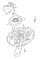
- a moment and magnet detecting equipment of an electric bicycle in accordance with the present invention has a transmitting assembly 10, a driving assembly 20 and a fixing assembly 30.
- the transmitting assembly 10 has a transmitting plate 11 and an outer loop 12.
- the transmitting plate 11 may be quadrilateral, pentagonal, hexagonal or polygonal and has an attaching side, a mounting side, multiple corners, a center, multiple threaded holes 111, a mounting recess 112, multiple transmitting teeth 113 and a center hole 114.
- the transmitting plate 11 is pentagonal and has five corners, five threaded holes 111 any five transmitting teeth 113 to fit with the pentagonal transmitting plate 11.
- the threaded holes 111 are respectively formed through the five corners of the transmitting plate 11 at same intervals and arranged in a circle around the center of the transmitting plate 11.
- the radiuses of the threaded holes 111 are the same.
- the mounting recess 112 is circular and formed in the inner side and around the center of the transmitting plate 11.
- the transmitting teeth 113 are radially formed on the inner side of the transmitting plate 11 in the mounting recess 112, are located at same intervals and protrude toward the center of the transmitting plate 11, and may be three, four or multiple in the amount.
- Each transmitting tooth 113 is cubic and has a front side and a rear side opposite to each other.
- the center hole 114 is circular and formed through the center of the transmitting plate 11 and has an inner diameter.
- the outer loop 12 is mounted in the inner side around the center hole 114 of the transmitting plate 11, is arranged between the threaded holes 111 and the mounting recess 112 and is fastened by screws and has multiple outer magnets 121.
- the outer magnets 121 are mounted around the outer loop 12 at same intervals.
- the outer magnets 121 are twelve in the embodiment and may be ten or eight.
- the driving assembly 20 is mounted in the transmitting plate 11 and has a driving plate 21, a bearing 22, multiple springs 23, an inner loop 24 and a cover loop 25.
- the driving plate 21 is mounted in the mounting recess 112 surrounded by the transmitting teeth 113 and has an inner side, an outer side, an outer ring edge, a shaft hole 211, a bearing groove 212, multiple driving teeth 213 and a cylinder 214.
- the shaft hole 211 is rectangular and formed through the driving plate 21 and has an inner diameter shorter than the inner diameter of the center hole 114 of the transmitting plate 11.
- the bearing groove 212 is formed in the inner side of the driving plate 21 around the shaft hole 211.
- the driving teeth 213 are radially formed on and protruding from the outer ring edge of the driving plate 21, are located at same intervals and respectively press against and correspond to the transmitting teeth 113 of the transmitting plate 11.
- Each driving tooth 213 is cubic and has an abutting side abutting the front side of the corresponded transmitting tooth 113 and a pressing side opposite to the abutting side.
- the driving teeth 213 may be three, four or multiple in the amount according to the transmitting teeth 113.
- the cylinder 214 protrudes from the outer surface of the driving plate 21 and rotatably inserted into the center hole 114 of the transmitting plate 11.
- the bearing 22 is mounted in the bearing groove 212 of the driving plate 21.
- the springs 23 are respectively mounted between the transmitting teeth 113 of the transmitting plate 11 and the driving teeth 213 of the driving plate 21 in the mounting recess 112.
- Each spring 23 has two ends respectively abutting the rear side of one of the transmitting tooth 113 and the spring side of one of the driving teeth 213 next to the transmitting tooth 113.
- the springs 23 may be four, five, six or multiple according to the amount of the transmitting teeth 113 and the driving teeth 213.
- the inner loop 24 is mounted in the inner side of the driving plate 21 and fastened by screws and has twelve outer magnets 241.
- the outer magnets 241 are mounted around the inner loop 24, are located at same intervals and are respectively aligned to and correspond to the outer magnets 121 of the outer loop 12.
- the cover loop 25 is mounted on the inner surface of the driving plate 21 and covers and keeps the transmitting teeth 113, the driving teeth 213 and the springs 23 in the mounting recess 112 of the transmitting plate 11.
- the outer magnets 241 are twelve in the embodiment and may be ten or eight according to and correspond to the inner magnets 121.
- the fixing assembly 30 faces the transmitting assembly 10 and the driving assembly 20 and has a fixing plate 31. an outer magnetic sensor 32 and an inner magnetic sensor 33.
- the fixing plate 31 faces the driving plate 21 and covers the mounting recess 112 and the outer loop 12 and has a covering surface, a fixing surface, a through hole 311, a mounting tube 312. a setting recess 313 and a fixing recess 314.
- the covering surface of the fixing plate 31 faces the transmitting assembly 10 and covers the mounting recess 112 and the outer loop 12.
- the through hole 311 is formed through the fixing plate 31 and communicates with the shaft hole 211 of the driving plate 21.
- the mounting tube 312 is formed on and protrude from the inner surface of the fixing plate 31 around the through hole 311 and is inserted into the bearing groove 212 to surround and cover the bearing 22.
- the setting recess 313 is formed in the inner surface of the fixing plate 31.
- the fixing recess 314 is rectangular and formed in the outer surface of the fixing plate 31 around the through hole 311.
- the outer magnetic sensor 32 is mounted in the setting recess 313 and aligned with the inner loop 24 and faces and reacts with the outer magnets 241.
- the inner magnetic sensor 33 is mounted in the setting recess 313 and aligned with the outer loop 12 and faces and reacts with the inner magnets 121.
- the outer magnetic sensor 32 and the inner magnetic sensor 33 may be Hall effect sensors.
- the moment and magnet detecting equipment of an electric bicycle is mounted on the electric bicycle.
- the electric bicycle has a chain wheel 40, a bottom bracket 41, two end covers 42, a rotating shaft 43 and crank 44.
- the bottom bracket 41 is implemented on a frame of the electric bicycle.
- the end covers 42 are respectively mounted opposite on the bottom bracket 41 and each has a fixing protrusion shaped in cubic.
- the rotating shaft 43 is rotatably mounted through the bottom bracket 41 and extends out from the end covers 42 and has a connecting end.
- the chain wheel 40 is connected to the moment and magnet detecting equipment of an electric bicycle and mounted around the connecting end of the rotating shaft 43.
- the crank 44 has a pivoting end being mounted on the connecting end of the rotating shaft 43.
- the moment and magnet detecting equipment of an electric bicycle is set between the bottom bracket 41 and the chain wheel 40 and has simple compositions and may be set easily and conveniently.
- the user steps the foot pedals of the bicycle to rotate the crank 44 and drive the rotating shaft 43.
- the rotating shaft 43 is rotated to rotate the driving plate 21.
- the driving teeth 213 of the driving plate 21 are rotated to press the springs 23 and push the transmitting teeth 113 of the transmitting plate 11 and rotate the transmitting plate 11. Because the transmitting plate 11 is mounted on the chain wheel 40, the chain wheel 40 is driven to rotate and make the electric bicycle working.
- the outer loop 12 and the inner loop 24 are driven to rotate with the transmitting assembly 10 and the driving assembly 20.
- the outer magnets 121 on the outer loop 12 and the outer magnets 241 on the inner loop 24 are respectively passed through the inner magnetic sensor 33 and the outer magnetic sensor 32 and excite potentials.
- the crank 44 is rotated by an increasing driving moment, a rotating moment of the driving teeth 213 of the driving plate 21 will increase accordingly. This indicates that the user is in a strenuous situation. Therefore, the driving plate 21 is rotated faster than the transmitting plate 11.
- the time of each outer magnets 241passing through the outer magnetic sensor 32 is earlier than the time of the corresponded outer magnet 121passing through the inner magnetic sensor 33. According to the change of the potential between the outer magnetic sensor 32 and the inner magnetic sensor 33, a motor of the electric bicycle is driven to output more power to rotate the chain wheel 40 and make the user relax.
Landscapes
- Engineering & Computer Science (AREA)
- Chemical & Material Sciences (AREA)
- Combustion & Propulsion (AREA)
- Physics & Mathematics (AREA)
- Transportation (AREA)
- Mechanical Engineering (AREA)
- Electromagnetism (AREA)
- General Physics & Mathematics (AREA)
- Connection Of Motors, Electrical Generators, Mechanical Devices, And The Like (AREA)
- Force Measurement Appropriate To Specific Purposes (AREA)
Claims (6)
- Moment- und Magneterfassungsausrüstung für ein elektrisches Fahrrad, umfassend einen Übertragungsaufbau (10), einen Antriebsaufbau (20) und einen Befestigungsaufbau (30), wobei:der Übertragungsaufbau (10) aufweist:eine Übertragungsplatte (11) miteiner Anbauseite;einer Befestigungsseite, welche gegenüber der Anbauseite ist;einer Mehrzahl von Ecken;einem Mittelpunkt;einer Mehrzahl von Gewindebohrungen (111), jeweils durch die Ecken der Übertragungsplatte (11) ausgebildet;einer Befestigungsvertiefung (112), welche auf der Innenseite und um den Mittelpunkt der Übertragungsplatte (11) ausgebildet ist;einer Mehrzahl von Zähnen (113), welche radial auf der Innenseite der Übertragungsplatte (11) in der Befestigungsvertiefung (112) ausgebildet sind und in Richtung des Mittelpunkts der Übertragungsplatte (11) vorragen;undeine Mittelpunktsbohrung (114), welche durch den Mittelpunkt der Übertragungsplatte (11) ausgebildet ist; undeinen äußeren Ring (12), welcher auf der Innenseite um die Mittelpunktsbohrung (114) angebracht ist und eine Mehrzahl von äußeren Magneten (121) aufweist, die um den äußeren Ring (12) angebracht sind;der Antriebsaufbau (20) in der Übertragungsplatte (11) angebracht ist, umfassend:eine Antriebsplatte (21), welche in der Befestigungsvertiefung (112) angebracht ist und aufweist:eine Innenseite;eine Außenseite, welche sich gegenüber der Außenseite befindet;eine äußere Ringkante;eine Wellenbohrung (211), welche durch die Antriebsplatte ausgebildet ist;eine Lagernut (212), welche auf der Innenseite der Antriebsplatte (21) um die Wellenbohrung (211) herum ausgebildet ist;eine Mehrzahl von Antriebszähnen (213), welche radial auf der äußeren Ringkante der Antriebsplatte (21) ausgebildet sind und jeweils den Übertragungszähnen (113) entsprechend angeordnet sind;ein Lager (22), welches in der Lagernut (212) der Antriebsplatte (21) angebracht ist;eine Mehrzahl von Federn (23), welche jeweils zwischen den aufeinander abgestimmten Übertragungszähnen (113) und den Antriebszähnen (213) angebracht sind; und einen inneren Ring (24), welcher auf der Innenseite der Antriebsplatte (21) angebracht ist und eine Mehrzahl von inneren Magneten (241) aufweist, die um den inneren Ring (24) angebracht sind;der Befestigungsaufbau (30) dem Übertragungsaufbau (10) und dem Antriebsaufbau (20) zugewandt ist und aufweist:eine Befestigungsplatte (31), welche die Befestigungsvertiefung (112) und den äußeren Ring (12) abdeckt und aufweist:eine Abdeckungsfläche, welche dem Übertragungsaufbau (10) zugewandt ist;eine Befestigungsfläche, welche gegenüber der Abdeckungsfläche liegt;eine Durchgangsbohrung (311), welche durch die Befestigungsplatte (31) ausgebildet ist;ein Befestigungsrohr (312), welches auf der inneren Fläche der Befestigungsplatte (31) ausgebildet ist unddavon um die Durchgangsbohrung (311) herum vorragt undin die Lagernut (212) eingeschoben wird, um um das Lager (22) herum angebracht zu sein und dieses abzudecken; undeine Befestigungsvertiefung (314), welche auf der äußeren Fläche der Befestigungsplatte (31) um die Durchgangsbohrung (311) herum ausgebildet ist; undeinen äußeren Magnetsensor (33), welcher in der Abdeckungsfläche der Befestigungsplatte (31) angebracht ist und mit dem äußeren Ring (12) gefluchtet ist unddie äußeren Magneten (121) erfasst; undeinen inneren Magnetsensor (32), welcher in der Abdeckungsfläche der Befestigungsplatte (31) angebracht ist und mit dem inneren Ring (24) gefluchtet ist und die äußeren Magneten (241) erfasst.
- Moment- und Magneterfassungsausrüstung für ein elektrisches Fahrrad nach Anspruch 1, wobei
jeder übertragende Zahn (113) ein gleiches Intervall zu den benachbarten übertragenden Zähnen (113) aufweist;
die Antriebszähne (213) mit gleichen Intervallen angeordnet sind; und
der Antriebsaufbau (20) des weiteren einen Abdeckungsring (25) aufweist, welcher auf der inneren Fläche der Antriebsplatte (21) angebracht ist und die Übertragungszähne (113), die Antriebszähne (213) und die Federn (23) in der Befestigungsvertiefung (112) der Übertragungsplatte (11) abdeckt und hält. - Moment- und Magneterfassungsausrüstung für ein elektrisches Fahrrad nach Anspruch 1 oder 2, wobei die Mittelpunktsbohrung (114) rund ist; und
der Zylinder (214) von der äußeren Fläche der Antriebsplatte (21) vorragt und drehbar in die Mittelpunktsbohrung (114) der Übertragungsplatte (11) eingeschoben ist. - Moment- und Magneterfassungsausrüstung für ein elektrisches Fahrrad nach Anspruch 3, wobei die äußeren Magnete (121) in Menge und Position den inneren Magneten (241) entsprechen.
- Moment- und Magneterfassungsausrüstung für ein elektrisches Fahrrad nach Anspruch 4, wobei
der äußere Magnetsensor (33) und der innere Magnetsensor (32) jeweils in einer Einsetzvertiefung (313) angebracht sind. - Moment- und Magneterfassungsausrüstung für ein elektrisches Fahrrad nach Anspruch 5, wobei
die Übertragungsplatte (11) regelmäßig fünfeckig ist und aufweist:fünf Ecken;fünf Gewindebohrungen (111), welche jeweils durch die Ecken der Übertragungsplatte (11) ausgebildet sind; und wobeidie Übertragungszähne (113) und die Antriebszähne (213) jeweils in der Anzahl von fünf ausgeführt sind; unddie äußeren Magnete (121) und die inneren Magnete (241) jeweils in der Anzahl von zwölf ausgeführt sind.
Priority Applications (1)
| Application Number | Priority Date | Filing Date | Title |
|---|---|---|---|
| EP20100169987 EP2409909B1 (de) | 2010-07-19 | 2010-07-19 | Drehmoment- und Magneterkennungsausrüstung für ein elektrisches Fahrrad |
Applications Claiming Priority (1)
| Application Number | Priority Date | Filing Date | Title |
|---|---|---|---|
| EP20100169987 EP2409909B1 (de) | 2010-07-19 | 2010-07-19 | Drehmoment- und Magneterkennungsausrüstung für ein elektrisches Fahrrad |
Publications (2)
| Publication Number | Publication Date |
|---|---|
| EP2409909A1 EP2409909A1 (de) | 2012-01-25 |
| EP2409909B1 true EP2409909B1 (de) | 2012-11-14 |
Family
ID=43027728
Family Applications (1)
| Application Number | Title | Priority Date | Filing Date |
|---|---|---|---|
| EP20100169987 Not-in-force EP2409909B1 (de) | 2010-07-19 | 2010-07-19 | Drehmoment- und Magneterkennungsausrüstung für ein elektrisches Fahrrad |
Country Status (1)
| Country | Link |
|---|---|
| EP (1) | EP2409909B1 (de) |
Families Citing this family (4)
| Publication number | Priority date | Publication date | Assignee | Title |
|---|---|---|---|---|
| TWI515145B (zh) * | 2012-12-03 | 2016-01-01 | 黃永松 | 扭力感測齒盤機構 |
| GB201303776D0 (en) * | 2013-03-01 | 2013-04-17 | Karbon Kinetics Ltd | Non contact pedal crank torque for a bicycle |
| JP6211190B2 (ja) * | 2014-06-18 | 2017-10-11 | サンスター技研株式会社 | 電動アシスト移動体に使用するためのセンサ、電動アシストユニット、電動アシスト移動体、および、トルク検出方法 |
| CN219601530U (zh) * | 2023-03-06 | 2023-08-29 | 上海微熹动力科技有限公司 | 一种无线传输自行车牙盘轮辐式力矩传感器 |
Family Cites Families (3)
| Publication number | Priority date | Publication date | Assignee | Title |
|---|---|---|---|---|
| DE19617959C1 (de) * | 1996-05-06 | 1997-10-23 | Werner K Dipl Ing Mayer | Vorrichtung zur Erfassung der Tretkraft bei einem Fahrrad |
| JP3163046B2 (ja) * | 1996-10-25 | 2001-05-08 | 三洋電機株式会社 | 補助動力付人力走行車 |
| JP2000002604A (ja) * | 1998-06-18 | 2000-01-07 | Honda Motor Co Ltd | 動力アシスト車両の入力トルク検出装置 |
-
2010
- 2010-07-19 EP EP20100169987 patent/EP2409909B1/de not_active Not-in-force
Also Published As
| Publication number | Publication date |
|---|---|
| EP2409909A1 (de) | 2012-01-25 |
Similar Documents
| Publication | Publication Date | Title |
|---|---|---|
| US20130162112A1 (en) | Motor-Gear Unit | |
| US8650972B2 (en) | Sensor apparatus for a bicycle hub | |
| EP2409909B1 (de) | Drehmoment- und Magneterkennungsausrüstung für ein elektrisches Fahrrad | |
| JP5479436B2 (ja) | トルク検出装置 | |
| US9273947B2 (en) | Sensing magnet apparatus for motor | |
| EP2873601B1 (de) | Elektrisches Fahrrad und Steuerverfahren dafür | |
| TWI424938B (zh) | 電動輔助轉輪機構 | |
| EP2423093A1 (de) | Fahrrad mit Hilfsantrieb | |
| CN114302845B (zh) | 自行车驱动系统及套件 | |
| EP4155182A1 (de) | Strommodul eines elektrisch unterstützten fahrrads | |
| EP3632626B1 (de) | Elektrowerkzeug | |
| EP2479099A1 (de) | Leistungsausgabegerät für ein Fahrzeug | |
| CN111295325A (zh) | 用于自行车的电气驱动装置 | |
| JP2019042814A (ja) | 電動工具 | |
| WO2018205713A1 (zh) | 一种电动车力矩感应测量式电机及电动自行车 | |
| JP2003095181A (ja) | 電動アシスト自転車 | |
| TWM553291U (zh) | 自行車用變速單元 | |
| TW201313550A (zh) | 電動腳踏車 | |
| EP3480104B1 (de) | Kurbelantriebsmotor für elektrisches fahrrad mit automatischer gangschaltung | |
| TWI830469B (zh) | 中置馬達扭力及馬達位置感測系統化整合機構及其方法 | |
| TWI564182B (zh) | 電動自行車及其扭矩傳感器 | |
| JP5140862B2 (ja) | 電動自転車用踏込みモーメント伝動感知装置 | |
| JP2003095179A (ja) | 電動アシスト自転車 | |
| CN117985171A (zh) | 中置马达扭力及马达位置感测系统化整合机构及其方法 | |
| US20170191886A1 (en) | Torque detecting device |
Legal Events
| Date | Code | Title | Description |
|---|---|---|---|
| 17P | Request for examination filed |
Effective date: 20110413 |
|
| AK | Designated contracting states |
Kind code of ref document: A1 Designated state(s): AL AT BE BG CH CY CZ DE DK EE ES FI FR GB GR HR HU IE IS IT LI LT LU LV MC MK MT NL NO PL PT RO SE SI SK SM TR |
|
| AX | Request for extension of the european patent |
Extension state: BA ME RS |
|
| PUAI | Public reference made under article 153(3) epc to a published international application that has entered the european phase |
Free format text: ORIGINAL CODE: 0009012 |
|
| RIC1 | Information provided on ipc code assigned before grant |
Ipc: G01L 3/14 20060101ALI20120131BHEP Ipc: B62M 6/50 20100101AFI20120131BHEP |
|
| GRAP | Despatch of communication of intention to grant a patent |
Free format text: ORIGINAL CODE: EPIDOSNIGR1 |
|
| RIN1 | Information on inventor provided before grant (corrected) |
Inventor name: HUANG, SAN-I Inventor name: LIN, CHENG-YUAN Inventor name: FANG, SEN-HSIEN Inventor name: CHEN, HONG-FANG |
|
| GRAS | Grant fee paid |
Free format text: ORIGINAL CODE: EPIDOSNIGR3 |
|
| GRAA | (expected) grant |
Free format text: ORIGINAL CODE: 0009210 |
|
| AK | Designated contracting states |
Kind code of ref document: B1 Designated state(s): AL AT BE BG CH CY CZ DE DK EE ES FI FR GB GR HR HU IE IS IT LI LT LU LV MC MK MT NL NO PL PT RO SE SI SK SM TR |
|
| REG | Reference to a national code |
Ref country code: GB Ref legal event code: FG4D |
|
| REG | Reference to a national code |
Ref country code: AT Ref legal event code: REF Ref document number: 583826 Country of ref document: AT Kind code of ref document: T Effective date: 20121115 Ref country code: CH Ref legal event code: EP Ref country code: CH Ref legal event code: NV Representative=s name: SCHNEIDER FELDMANN AG PATENT- UND MARKENANWAEL, CH |
|
| REG | Reference to a national code |
Ref country code: IE Ref legal event code: FG4D |
|
| REG | Reference to a national code |
Ref country code: DE Ref legal event code: R096 Ref document number: 602010003586 Country of ref document: DE Effective date: 20130110 |
|
| REG | Reference to a national code |
Ref country code: SE Ref legal event code: TRGR |
|
| REG | Reference to a national code |
Ref country code: NL Ref legal event code: T3 |
|
| REG | Reference to a national code |
Ref country code: AT Ref legal event code: MK05 Ref document number: 583826 Country of ref document: AT Kind code of ref document: T Effective date: 20121114 |
|
| REG | Reference to a national code |
Ref country code: LT Ref legal event code: MG4D |
|
| PG25 | Lapsed in a contracting state [announced via postgrant information from national office to epo] |
Ref country code: HR Free format text: LAPSE BECAUSE OF FAILURE TO SUBMIT A TRANSLATION OF THE DESCRIPTION OR TO PAY THE FEE WITHIN THE PRESCRIBED TIME-LIMIT Effective date: 20121114 Ref country code: FI Free format text: LAPSE BECAUSE OF FAILURE TO SUBMIT A TRANSLATION OF THE DESCRIPTION OR TO PAY THE FEE WITHIN THE PRESCRIBED TIME-LIMIT Effective date: 20121114 Ref country code: ES Free format text: LAPSE BECAUSE OF FAILURE TO SUBMIT A TRANSLATION OF THE DESCRIPTION OR TO PAY THE FEE WITHIN THE PRESCRIBED TIME-LIMIT Effective date: 20130225 Ref country code: LT Free format text: LAPSE BECAUSE OF FAILURE TO SUBMIT A TRANSLATION OF THE DESCRIPTION OR TO PAY THE FEE WITHIN THE PRESCRIBED TIME-LIMIT Effective date: 20121114 Ref country code: NO Free format text: LAPSE BECAUSE OF FAILURE TO SUBMIT A TRANSLATION OF THE DESCRIPTION OR TO PAY THE FEE WITHIN THE PRESCRIBED TIME-LIMIT Effective date: 20130214 |
|
| PG25 | Lapsed in a contracting state [announced via postgrant information from national office to epo] |
Ref country code: BE Free format text: LAPSE BECAUSE OF FAILURE TO SUBMIT A TRANSLATION OF THE DESCRIPTION OR TO PAY THE FEE WITHIN THE PRESCRIBED TIME-LIMIT Effective date: 20121114 Ref country code: LV Free format text: LAPSE BECAUSE OF FAILURE TO SUBMIT A TRANSLATION OF THE DESCRIPTION OR TO PAY THE FEE WITHIN THE PRESCRIBED TIME-LIMIT Effective date: 20121114 Ref country code: PL Free format text: LAPSE BECAUSE OF FAILURE TO SUBMIT A TRANSLATION OF THE DESCRIPTION OR TO PAY THE FEE WITHIN THE PRESCRIBED TIME-LIMIT Effective date: 20121114 Ref country code: PT Free format text: LAPSE BECAUSE OF FAILURE TO SUBMIT A TRANSLATION OF THE DESCRIPTION OR TO PAY THE FEE WITHIN THE PRESCRIBED TIME-LIMIT Effective date: 20130314 Ref country code: SI Free format text: LAPSE BECAUSE OF FAILURE TO SUBMIT A TRANSLATION OF THE DESCRIPTION OR TO PAY THE FEE WITHIN THE PRESCRIBED TIME-LIMIT Effective date: 20121114 |
|
| PG25 | Lapsed in a contracting state [announced via postgrant information from national office to epo] |
Ref country code: AT Free format text: LAPSE BECAUSE OF FAILURE TO SUBMIT A TRANSLATION OF THE DESCRIPTION OR TO PAY THE FEE WITHIN THE PRESCRIBED TIME-LIMIT Effective date: 20121114 |
|
| PG25 | Lapsed in a contracting state [announced via postgrant information from national office to epo] |
Ref country code: BG Free format text: LAPSE BECAUSE OF FAILURE TO SUBMIT A TRANSLATION OF THE DESCRIPTION OR TO PAY THE FEE WITHIN THE PRESCRIBED TIME-LIMIT Effective date: 20130214 Ref country code: EE Free format text: LAPSE BECAUSE OF FAILURE TO SUBMIT A TRANSLATION OF THE DESCRIPTION OR TO PAY THE FEE WITHIN THE PRESCRIBED TIME-LIMIT Effective date: 20121114 Ref country code: DK Free format text: LAPSE BECAUSE OF FAILURE TO SUBMIT A TRANSLATION OF THE DESCRIPTION OR TO PAY THE FEE WITHIN THE PRESCRIBED TIME-LIMIT Effective date: 20121114 Ref country code: CZ Free format text: LAPSE BECAUSE OF FAILURE TO SUBMIT A TRANSLATION OF THE DESCRIPTION OR TO PAY THE FEE WITHIN THE PRESCRIBED TIME-LIMIT Effective date: 20121114 Ref country code: SK Free format text: LAPSE BECAUSE OF FAILURE TO SUBMIT A TRANSLATION OF THE DESCRIPTION OR TO PAY THE FEE WITHIN THE PRESCRIBED TIME-LIMIT Effective date: 20121114 |
|
| PG25 | Lapsed in a contracting state [announced via postgrant information from national office to epo] |
Ref country code: RO Free format text: LAPSE BECAUSE OF FAILURE TO SUBMIT A TRANSLATION OF THE DESCRIPTION OR TO PAY THE FEE WITHIN THE PRESCRIBED TIME-LIMIT Effective date: 20121114 Ref country code: IT Free format text: LAPSE BECAUSE OF FAILURE TO SUBMIT A TRANSLATION OF THE DESCRIPTION OR TO PAY THE FEE WITHIN THE PRESCRIBED TIME-LIMIT Effective date: 20121114 |
|
| PLBE | No opposition filed within time limit |
Free format text: ORIGINAL CODE: 0009261 |
|
| STAA | Information on the status of an ep patent application or granted ep patent |
Free format text: STATUS: NO OPPOSITION FILED WITHIN TIME LIMIT |
|
| 26N | No opposition filed |
Effective date: 20130815 |
|
| PG25 | Lapsed in a contracting state [announced via postgrant information from national office to epo] |
Ref country code: CY Free format text: LAPSE BECAUSE OF FAILURE TO SUBMIT A TRANSLATION OF THE DESCRIPTION OR TO PAY THE FEE WITHIN THE PRESCRIBED TIME-LIMIT Effective date: 20121114 |
|
| REG | Reference to a national code |
Ref country code: DE Ref legal event code: R097 Ref document number: 602010003586 Country of ref document: DE Effective date: 20130815 |
|
| PG25 | Lapsed in a contracting state [announced via postgrant information from national office to epo] |
Ref country code: MC Free format text: LAPSE BECAUSE OF FAILURE TO SUBMIT A TRANSLATION OF THE DESCRIPTION OR TO PAY THE FEE WITHIN THE PRESCRIBED TIME-LIMIT Effective date: 20121114 |
|
| REG | Reference to a national code |
Ref country code: IE Ref legal event code: MM4A |
|
| PG25 | Lapsed in a contracting state [announced via postgrant information from national office to epo] |
Ref country code: IE Free format text: LAPSE BECAUSE OF NON-PAYMENT OF DUE FEES Effective date: 20130719 |
|
| PG25 | Lapsed in a contracting state [announced via postgrant information from national office to epo] |
Ref country code: SM Free format text: LAPSE BECAUSE OF FAILURE TO SUBMIT A TRANSLATION OF THE DESCRIPTION OR TO PAY THE FEE WITHIN THE PRESCRIBED TIME-LIMIT Effective date: 20121114 |
|
| PG25 | Lapsed in a contracting state [announced via postgrant information from national office to epo] |
Ref country code: MT Free format text: LAPSE BECAUSE OF FAILURE TO SUBMIT A TRANSLATION OF THE DESCRIPTION OR TO PAY THE FEE WITHIN THE PRESCRIBED TIME-LIMIT Effective date: 20121114 Ref country code: TR Free format text: LAPSE BECAUSE OF FAILURE TO SUBMIT A TRANSLATION OF THE DESCRIPTION OR TO PAY THE FEE WITHIN THE PRESCRIBED TIME-LIMIT Effective date: 20121114 |
|
| PG25 | Lapsed in a contracting state [announced via postgrant information from national office to epo] |
Ref country code: LU Free format text: LAPSE BECAUSE OF NON-PAYMENT OF DUE FEES Effective date: 20130719 Ref country code: HU Free format text: LAPSE BECAUSE OF FAILURE TO SUBMIT A TRANSLATION OF THE DESCRIPTION OR TO PAY THE FEE WITHIN THE PRESCRIBED TIME-LIMIT; INVALID AB INITIO Effective date: 20100719 Ref country code: MK Free format text: LAPSE BECAUSE OF FAILURE TO SUBMIT A TRANSLATION OF THE DESCRIPTION OR TO PAY THE FEE WITHIN THE PRESCRIBED TIME-LIMIT Effective date: 20121114 |
|
| PG25 | Lapsed in a contracting state [announced via postgrant information from national office to epo] |
Ref country code: GR Free format text: LAPSE BECAUSE OF NON-PAYMENT OF DUE FEES Effective date: 20121114 |
|
| REG | Reference to a national code |
Ref country code: FR Ref legal event code: PLFP Year of fee payment: 7 |
|
| PG25 | Lapsed in a contracting state [announced via postgrant information from national office to epo] |
Ref country code: IS Free format text: LAPSE BECAUSE OF FAILURE TO SUBMIT A TRANSLATION OF THE DESCRIPTION OR TO PAY THE FEE WITHIN THE PRESCRIBED TIME-LIMIT Effective date: 20121114 |
|
| PGFP | Annual fee paid to national office [announced via postgrant information from national office to epo] |
Ref country code: GB Payment date: 20160523 Year of fee payment: 7 |
|
| PGFP | Annual fee paid to national office [announced via postgrant information from national office to epo] |
Ref country code: FR Payment date: 20160516 Year of fee payment: 7 |
|
| PGFP | Annual fee paid to national office [announced via postgrant information from national office to epo] |
Ref country code: NL Payment date: 20160721 Year of fee payment: 7 |
|
| PGFP | Annual fee paid to national office [announced via postgrant information from national office to epo] |
Ref country code: DE Payment date: 20160728 Year of fee payment: 7 |
|
| PGFP | Annual fee paid to national office [announced via postgrant information from national office to epo] |
Ref country code: SE Payment date: 20160721 Year of fee payment: 7 |
|
| PGFP | Annual fee paid to national office [announced via postgrant information from national office to epo] |
Ref country code: CH Payment date: 20161026 Year of fee payment: 7 |
|
| REG | Reference to a national code |
Ref country code: DE Ref legal event code: R119 Ref document number: 602010003586 Country of ref document: DE |
|
| REG | Reference to a national code |
Ref country code: CH Ref legal event code: PL |
|
| REG | Reference to a national code |
Ref country code: NL Ref legal event code: MM Effective date: 20170801 |
|
| REG | Reference to a national code |
Ref country code: SE Ref legal event code: EUG |
|
| GBPC | Gb: european patent ceased through non-payment of renewal fee |
Effective date: 20170719 |
|
| REG | Reference to a national code |
Ref country code: FR Ref legal event code: ST Effective date: 20180330 |
|
| PG25 | Lapsed in a contracting state [announced via postgrant information from national office to epo] |
Ref country code: SE Free format text: LAPSE BECAUSE OF NON-PAYMENT OF DUE FEES Effective date: 20170720 Ref country code: GB Free format text: LAPSE BECAUSE OF NON-PAYMENT OF DUE FEES Effective date: 20170719 Ref country code: CH Free format text: LAPSE BECAUSE OF NON-PAYMENT OF DUE FEES Effective date: 20170731 Ref country code: LI Free format text: LAPSE BECAUSE OF NON-PAYMENT OF DUE FEES Effective date: 20170731 Ref country code: NL Free format text: LAPSE BECAUSE OF NON-PAYMENT OF DUE FEES Effective date: 20170801 Ref country code: DE Free format text: LAPSE BECAUSE OF NON-PAYMENT OF DUE FEES Effective date: 20180201 |
|
| PG25 | Lapsed in a contracting state [announced via postgrant information from national office to epo] |
Ref country code: FR Free format text: LAPSE BECAUSE OF NON-PAYMENT OF DUE FEES Effective date: 20170731 |
|
| PG25 | Lapsed in a contracting state [announced via postgrant information from national office to epo] |
Ref country code: AL Free format text: LAPSE BECAUSE OF FAILURE TO SUBMIT A TRANSLATION OF THE DESCRIPTION OR TO PAY THE FEE WITHIN THE PRESCRIBED TIME-LIMIT Effective date: 20121114 |