EP2409936A1 - Wassertank und Verfahren zum Aufbau eines solchen - Google Patents
Wassertank und Verfahren zum Aufbau eines solchen Download PDFInfo
- Publication number
- EP2409936A1 EP2409936A1 EP10170135A EP10170135A EP2409936A1 EP 2409936 A1 EP2409936 A1 EP 2409936A1 EP 10170135 A EP10170135 A EP 10170135A EP 10170135 A EP10170135 A EP 10170135A EP 2409936 A1 EP2409936 A1 EP 2409936A1
- Authority
- EP
- European Patent Office
- Prior art keywords
- membrane
- water tank
- sidewalls
- mastic
- tank according
- Prior art date
- Legal status (The legal status is an assumption and is not a legal conclusion. Google has not performed a legal analysis and makes no representation as to the accuracy of the status listed.)
- Granted
Links
Images

Classifications
-
- B—PERFORMING OPERATIONS; TRANSPORTING
- B65—CONVEYING; PACKING; STORING; HANDLING THIN OR FILAMENTARY MATERIAL
- B65D—CONTAINERS FOR STORAGE OR TRANSPORT OF ARTICLES OR MATERIALS, e.g. BAGS, BARRELS, BOTTLES, BOXES, CANS, CARTONS, CRATES, DRUMS, JARS, TANKS, HOPPERS, FORWARDING CONTAINERS; ACCESSORIES, CLOSURES, OR FITTINGS THEREFOR; PACKAGING ELEMENTS; PACKAGES
- B65D90/00—Component parts, details or accessories for large containers
- B65D90/02—Wall construction
- B65D90/04—Linings
- B65D90/046—Flexible liners, e.g. loosely positioned in the container
-
- B—PERFORMING OPERATIONS; TRANSPORTING
- B65—CONVEYING; PACKING; STORING; HANDLING THIN OR FILAMENTARY MATERIAL
- B65D—CONTAINERS FOR STORAGE OR TRANSPORT OF ARTICLES OR MATERIALS, e.g. BAGS, BARRELS, BOTTLES, BOXES, CANS, CARTONS, CRATES, DRUMS, JARS, TANKS, HOPPERS, FORWARDING CONTAINERS; ACCESSORIES, CLOSURES, OR FITTINGS THEREFOR; PACKAGING ELEMENTS; PACKAGES
- B65D90/00—Component parts, details or accessories for large containers
-
- B—PERFORMING OPERATIONS; TRANSPORTING
- B65—CONVEYING; PACKING; STORING; HANDLING THIN OR FILAMENTARY MATERIAL
- B65D—CONTAINERS FOR STORAGE OR TRANSPORT OF ARTICLES OR MATERIALS, e.g. BAGS, BARRELS, BOTTLES, BOXES, CANS, CARTONS, CRATES, DRUMS, JARS, TANKS, HOPPERS, FORWARDING CONTAINERS; ACCESSORIES, CLOSURES, OR FITTINGS THEREFOR; PACKAGING ELEMENTS; PACKAGES
- B65D88/00—Large containers
- B65D88/02—Large containers rigid
- B65D88/06—Large containers rigid cylindrical
- B65D88/08—Large containers rigid cylindrical with a vertical axis
Definitions
- the invention relates to a watertight bottom of a steel water tank suitable for storage of sprinkler water for fire prevention.
- the invention also relates to a method for installing said bottom in a steel water tank.
- Another way of installing a watertight steel water tank is by providing an inner liner, e.g. in rubber.
- the inner liner covers the entire tank wall of the water tank and reaches up to the top, to above the water level. This solves the problems just mentioned, however there are some major drawbacks.
- a problem with this type of design is that the water tank starts leaking and becomes useless whenever the liner gets teared or damaged.
- Another problem is serious corrosion of the tank wall due to condensation between the liner and said wall.
- the invention provides a water tank for water storage, comprising sidewalls (1) mounted on a foundation (2) and a membrane (4) covering the foundation and extending upwards onto the inner sidewalls, whereby the membrane (4) edge ends under the water level.
- the membrane only extends up to a part of the sidewalls, being the part of space necessary for fixing the membrane to the lower part of the inner sidewalls.
- the membrane only extends onto a lower part of the sidewalls and does not reach tip to the top level of the tank. Because the membrane edge lies under the water level, there is a need for a watertight sealing of the membrane to the tank wall. This watertight sealing is provided by the embodiments of the present invention.
- the advantage of the water tank of the invention is that it is cheap, simple, easy, reliable and fast to install. Furthermore the water tank is perfectly watertight. A mimum amount of membrane material is used. Due to the small thickness of the membrane in comparison with a tank bottom filled with concrete, the height of the tank may decrease for the same capacity (volume) thereby creating a reasonable cost saving. The process of installation solely relies on one installer from start to end.
- said membrane (4) is watertightly applied between said inner sidewalls (1) and a fixation means (8) by means of bolts (9) in prepunched holes (5a, 5b) and mastic (6, 7, 10).
- said membrane (4) extends 10 to 50 cm up onto the sidewalls (1), preferably 10 to 30 cm, or any suitable distance for fixing the membrane to the sidewalls with a fixation means hereby cost-effectively applying only a minimum amount of membrane needed.
- At least one row of swell seal mastic (7) is provided in an uninterrupted watertight manner between the sidewalls (1) and the membrane (4).
- fixation means (8) is applied to the sidewalls (1) by means of two or more rows (I, II) of bolts (9). Said two or more rows (I, II) are preferably horizontal, i.e. parallel to the surface of the foundation or the bottom of the tank.
- a mastic (6) is provided in each hole (5a, 5b) in an uninterrupted watertight manner.
- a mastic (10) is provided in an uninterrupted watertight manner, between the lower end of the fixation means (8) and the membrane (4), between the upper edge of the fixation means (8) and the membrane (4), and between the membrane upper edge and the sidewalls.
- Said fixation means (8) comprises one or more reinforcing ribs (11) extending out of the surface of said fixation means.
- said reinforcing rib (11) is a bent edge or a seal edge.
- said fixation means (8) comprises one or more peripheral bands (8) of clamping plates, each band comprising two or more horizontal rows (I, II) of prepunched holes (5b) corresponding to prepunched holes (5a) in the sidewalls.
- the membrane (4) is preferably made of EPDM.
- a protective layer (3) is applied on the bottom between the foundation (2) and the membrane (4).
- a casing (12) holding gravel (13) is provided around the outside bottom of the tank for hiding a bolted (16) L-profile (14) by which the tank is mounted to the foundation (2).
- the invention also provides a method for constructing a water tank as described above, said method comprising the steps of: a) mounting the sidewalls (1) of a water tank onto a foundation (2); b) spreading a membrane (4) onto the foundation (2) and extending said membrane onto the inner sidewalls to a level under the water level; c) applying an uninterrupted swell seal mastic (7) between the membrane (4) and the sidewalls (1); d) applying an uninterrupted mastic (6) between the membrane (4) and the sidewall (1) at the level of the rows (I, II) of holes (5a); e) applying an uninterrupted mastic (6) between the membrane (4) and a clamping plate (8) at the level of the rows (I, II) of holes (5b); f) fixing the clamping plate (8) to the sidewalls (1) by means of bolts (9) through the holes (5a, 5b) and the mastic (6); g) applying mastic (10) to the edges of the clamping plate (8) and the membrane (4), sealing off any space between the
- the invention also provides for the use of a sprinkler water tank as described above for watertight storage.
- the water tank may be installed on any horizontal surface that is strong and stable enough to support the weight of the tank and the water in it.
- the water tank may be installed (on a concrete slab) on the ground, but may also be installed on a tower, a roof top or any other supporting means.
- Figure 1 shows a sectional view of a cylindrical water tank (1) placed on a concrete foundation (2).
- the tank is mounted level (tolerance of about 10 mm) and secured with anchor bolts into the concrete slab.
- the water tank is made of galvanized modular steel sheets, assembled with silo bolts and sealed with mastic.
- a protective layer (3) is placed on top of the concrete surface and partly extends up onto the sides of the tank. Examples of protective layers are geotextiles (300 gr/m 2 ) or equivalents.
- the membrane (4) is first positioned on top of the protective layer, in the center of the tank, in a specially packed embodiment. It is then opened to cover the bottom of the tank hereby partly extending up onto the sides of the tank, preferably 20 to 30 cm. As such the membrane (4) does not reach above the water level, but ends under the water level, inside the tank.
- the membrane is preferably made of EPDM (1.2 mm thickness) or equivalents.
- the tank wall is provided with prepunched holes (5a), preferably in two horizontal rows (I, II) parallel to the bottom of the tank.
- a mastic (6) is provided on the inside of the tank in an uninterrupted manner along each of the two horizontal rows (I, II) of prepunched holes.
- a swelling joint with swell seal mastic (7) is applied, also preferably in an uninterrupted manner.
- the swelling joint may be the same material as the mastic.
- the membrane (4) is pressed tightly onto the two rows (I, II) of mastic (6) and the swell seal mastic (7), hereby preventing any leaks of water.
- a clamping plate (8) provided with two horizontal rows (I, II) of prepunched holes (5b) is applied on top of the membrane and fixed to the corresponding rows of prepunched holes (5a) in the tank wall. Both rows of holes of the clamping plate (8) are also provided with mastic (6) in uninterrupted horizontal rows.
- the clamping plate (8) is fixed onto the tank wall (1) segment by segment by means of silo bolts (9) that fit into the holes (5a, 5b), hereby forming an uninterrupted peripheral clamping band (8).
- the upper and lower side of the clamping plate (8) is provided with an uninterrupted row of mastic (10), so as to firmly seal the clamping plate preventing any leakage of water from the tank.
- the clamping plate (8) has an upper edge (11) that is slightly folded open towards the center of the tank.
- Other embodiments of such a feature are possible.
- This embodiment here also eases the application of the mastic (10) into the space of the folded upper edge (11).
- an upstanding casing (12) is applied holding gravel (13) between the casing and the tank.
- An L-profile (14) is applied on to the tank wall and leveled with shims (15) and fixed by means of silo bolts (16) to tank wall (1) and with anchor bolts (16) to the concrete floor (2) to prevent gravel (13) from piercing through the bottom of the protective liner (3) and the membrane (4).
- the upstanding casing (12) is preferably about 15 cm high.
- the filled casing provides an esthetical look of the tank and protects any dirt or other material from entering under the side of the tank.
- the mastic (6, 7, 10) used for sealing is specially made for good adherence to both the galvanized steel tank and the (EPDM) membrane.
- Examples of mastics suitable for this purpose are AvascoFlex and AvascoRub or equivalents.
- the inside of the tank (1) may be protected against corrosion and fouling.
- the water inside the tank may also be treated against fouling.
- the tank is preferably grounded.
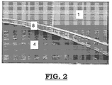
- Figure 2 shows a detailed view of the tank bottom, showing the sidewalls (1) and the membrane (4) on the bottom.
- the clamping plate (8) is mounted close to the bottom of the tank, but could also be mounted at any higher level.
- Figure 2 shows the empty watertight water tank which is ready for receiving water. As can be seen, the clamping plate is mounted at the lower bottom of the tank.
Landscapes
- Engineering & Computer Science (AREA)
- Mechanical Engineering (AREA)
- Filling Or Discharging Of Gas Storage Vessels (AREA)
Priority Applications (3)
| Application Number | Priority Date | Filing Date | Title |
|---|---|---|---|
| PL10170135T PL2409936T3 (pl) | 2010-07-20 | 2010-07-20 | Zbiornik wody, sposób wykonania takiego zbiornika i jego zastosowanie |
| EP10170135.7A EP2409936B1 (de) | 2010-07-20 | 2010-07-20 | Wassertank, Verfahren zum Aufbau eines solchen und Verwendung davon |
| BE2010/0759A BE1018789A3 (nl) | 2010-07-20 | 2010-12-23 | Watertankbodem. |
Applications Claiming Priority (1)
| Application Number | Priority Date | Filing Date | Title |
|---|---|---|---|
| EP10170135.7A EP2409936B1 (de) | 2010-07-20 | 2010-07-20 | Wassertank, Verfahren zum Aufbau eines solchen und Verwendung davon |
Publications (2)
| Publication Number | Publication Date |
|---|---|
| EP2409936A1 true EP2409936A1 (de) | 2012-01-25 |
| EP2409936B1 EP2409936B1 (de) | 2013-10-09 |
Family
ID=42937389
Family Applications (1)
| Application Number | Title | Priority Date | Filing Date |
|---|---|---|---|
| EP10170135.7A Not-in-force EP2409936B1 (de) | 2010-07-20 | 2010-07-20 | Wassertank, Verfahren zum Aufbau eines solchen und Verwendung davon |
Country Status (3)
| Country | Link |
|---|---|
| EP (1) | EP2409936B1 (de) |
| BE (1) | BE1018789A3 (de) |
| PL (1) | PL2409936T3 (de) |
Cited By (2)
| Publication number | Priority date | Publication date | Assignee | Title |
|---|---|---|---|---|
| CN104912208A (zh) * | 2015-06-17 | 2015-09-16 | 中冶南方工程技术有限公司 | 一种煤气柜柜外底部边缘板的防腐结构及处理方法 |
| CN112922425A (zh) * | 2021-03-24 | 2021-06-08 | 中化二建集团有限公司 | 无底螺栓连接式水罐防渗漏施工方法 |
Citations (7)
| Publication number | Priority date | Publication date | Assignee | Title |
|---|---|---|---|---|
| CH484798A (de) * | 1969-06-24 | 1970-01-31 | Ironflex Ag | Flüssigkeitsbehälter |
| US3545640A (en) * | 1968-09-12 | 1970-12-08 | Exxon Research Engineering Co | Protective gas seals for non-metallic tank bottoms |
| DE2202096A1 (de) * | 1972-01-18 | 1973-08-02 | Erhard Joos | Innenhuelle aus kunststoff zum auskleiden eines behaelters |
| US4068777A (en) * | 1975-11-25 | 1978-01-17 | Metal-Cladding, Inc. | Expansible bottom structure for fiberglass reinforced plastic tanks |
| DE29807285U1 (de) * | 1998-04-22 | 1998-07-30 | Utek Umweltschutztechnologien GmbH, 06785 Oranienbaum | Flachbodentank mit Leckschutzauskleidung |
| DE20104828U1 (de) * | 2001-03-20 | 2001-07-05 | Utek Umweltschutztechnologien GmbH, 06785 Oranienbaum | Verbindungssystem zur Befestigung einer flexiblen Kunststoffolie zur Leckschutzauskleidung an der Innenseite der Tankwandung eines Lagertanks |
| US20040217118A1 (en) * | 2003-04-29 | 2004-11-04 | John Nash | Portable liquid storage tank |
-
2010
- 2010-07-20 EP EP10170135.7A patent/EP2409936B1/de not_active Not-in-force
- 2010-07-20 PL PL10170135T patent/PL2409936T3/pl unknown
- 2010-12-23 BE BE2010/0759A patent/BE1018789A3/nl active
Patent Citations (7)
| Publication number | Priority date | Publication date | Assignee | Title |
|---|---|---|---|---|
| US3545640A (en) * | 1968-09-12 | 1970-12-08 | Exxon Research Engineering Co | Protective gas seals for non-metallic tank bottoms |
| CH484798A (de) * | 1969-06-24 | 1970-01-31 | Ironflex Ag | Flüssigkeitsbehälter |
| DE2202096A1 (de) * | 1972-01-18 | 1973-08-02 | Erhard Joos | Innenhuelle aus kunststoff zum auskleiden eines behaelters |
| US4068777A (en) * | 1975-11-25 | 1978-01-17 | Metal-Cladding, Inc. | Expansible bottom structure for fiberglass reinforced plastic tanks |
| DE29807285U1 (de) * | 1998-04-22 | 1998-07-30 | Utek Umweltschutztechnologien GmbH, 06785 Oranienbaum | Flachbodentank mit Leckschutzauskleidung |
| DE20104828U1 (de) * | 2001-03-20 | 2001-07-05 | Utek Umweltschutztechnologien GmbH, 06785 Oranienbaum | Verbindungssystem zur Befestigung einer flexiblen Kunststoffolie zur Leckschutzauskleidung an der Innenseite der Tankwandung eines Lagertanks |
| US20040217118A1 (en) * | 2003-04-29 | 2004-11-04 | John Nash | Portable liquid storage tank |
Cited By (3)
| Publication number | Priority date | Publication date | Assignee | Title |
|---|---|---|---|---|
| CN104912208A (zh) * | 2015-06-17 | 2015-09-16 | 中冶南方工程技术有限公司 | 一种煤气柜柜外底部边缘板的防腐结构及处理方法 |
| CN104912208B (zh) * | 2015-06-17 | 2017-06-13 | 中冶南方工程技术有限公司 | 一种煤气柜柜外底部边缘板的防腐结构及处理方法 |
| CN112922425A (zh) * | 2021-03-24 | 2021-06-08 | 中化二建集团有限公司 | 无底螺栓连接式水罐防渗漏施工方法 |
Also Published As
| Publication number | Publication date |
|---|---|
| BE1018789A3 (nl) | 2011-08-02 |
| EP2409936B1 (de) | 2013-10-09 |
| PL2409936T3 (pl) | 2014-03-31 |
Similar Documents
| Publication | Publication Date | Title |
|---|---|---|
| CN104160103B (zh) | 储罐隔热接头装置和方法 | |
| US20130029410A1 (en) | Digester tank for a biogas plant | |
| WO1990008077A1 (en) | Precast, prestressed concrete secondary containment vault | |
| CA2419430A1 (en) | Underground storage vault | |
| RU2755830C2 (ru) | Герметизированный и теплоизолированный резервуар | |
| EP2409936B1 (de) | Wassertank, Verfahren zum Aufbau eines solchen und Verwendung davon | |
| US8353142B2 (en) | System and method for sealing sump covers | |
| JP2010525998A (ja) | 燃料ディスペンサのサンプ | |
| CN113293801B (zh) | 一种电力电缆排管工井及其施工方法 | |
| US8770889B2 (en) | Method of waterproofing a containment sump | |
| CN215810386U (zh) | 拼装式储热罐结构 | |
| CN217053658U (zh) | 建筑 | |
| JP3826219B2 (ja) | コンクリート製貯槽とその施工法 | |
| CN210606555U (zh) | 一种高层建筑广告牌安装结构 | |
| AU2004205094B2 (en) | Storage System for Water | |
| US6199712B1 (en) | Manure storage container | |
| KR101077657B1 (ko) | 탈기장치 및 이를 이용한 방수시공방법 | |
| RU2788041C1 (ru) | Резервуар | |
| CN111779636B (zh) | 一种提高风力发电机组基础防水性能的方法 | |
| JP2021130469A (ja) | 蓄熱槽のスロッシング吸収機構 | |
| CN217460684U (zh) | 一种卡槽式预留缝施工结构 | |
| CN221461216U (zh) | 深基坑支护桩侵界加固结构 | |
| RU58373U1 (ru) | Пожарный водоем | |
| CN217924474U (zh) | 一种防水保温屋顶结构 | |
| CN219840157U (zh) | 一种预埋装配式喷塑防腐水箱 |
Legal Events
| Date | Code | Title | Description |
|---|---|---|---|
| AK | Designated contracting states |
Kind code of ref document: A1 Designated state(s): AL AT BE BG CH CY CZ DE DK EE ES FI FR GB GR HR HU IE IS IT LI LT LU LV MC MK MT NL NO PL PT RO SE SI SK SM TR |
|
| AX | Request for extension of the european patent |
Extension state: BA ME RS |
|
| PUAI | Public reference made under article 153(3) epc to a published international application that has entered the european phase |
Free format text: ORIGINAL CODE: 0009012 |
|
| RAP1 | Party data changed (applicant data changed or rights of an application transferred) |
Owner name: AVASCO INDUSTRIES |
|
| 17P | Request for examination filed |
Effective date: 20120719 |
|
| GRAP | Despatch of communication of intention to grant a patent |
Free format text: ORIGINAL CODE: EPIDOSNIGR1 |
|
| INTG | Intention to grant announced |
Effective date: 20130613 |
|
| GRAS | Grant fee paid |
Free format text: ORIGINAL CODE: EPIDOSNIGR3 |
|
| GRAA | (expected) grant |
Free format text: ORIGINAL CODE: 0009210 |
|
| AK | Designated contracting states |
Kind code of ref document: B1 Designated state(s): AL AT BE BG CH CY CZ DE DK EE ES FI FR GB GR HR HU IE IS IT LI LT LU LV MC MK MT NL NO PL PT RO SE SI SK SM TR |
|
| REG | Reference to a national code |
Ref country code: GB Ref legal event code: FG4D |
|
| REG | Reference to a national code |
Ref country code: CH Ref legal event code: EP Ref country code: AT Ref legal event code: REF Ref document number: 635450 Country of ref document: AT Kind code of ref document: T Effective date: 20131015 |
|
| REG | Reference to a national code |
Ref country code: IE Ref legal event code: FG4D |
|
| REG | Reference to a national code |
Ref country code: DE Ref legal event code: R096 Ref document number: 602010010787 Country of ref document: DE Effective date: 20131205 |
|
| REG | Reference to a national code |
Ref country code: NL Ref legal event code: T3 |
|
| REG | Reference to a national code |
Ref country code: AT Ref legal event code: MK05 Ref document number: 635450 Country of ref document: AT Kind code of ref document: T Effective date: 20131009 |
|
| PG25 | Lapsed in a contracting state [announced via postgrant information from national office to epo] |
Ref country code: SI Free format text: LAPSE BECAUSE OF FAILURE TO SUBMIT A TRANSLATION OF THE DESCRIPTION OR TO PAY THE FEE WITHIN THE PRESCRIBED TIME-LIMIT Effective date: 20131009 |
|
| REG | Reference to a national code |
Ref country code: LT Ref legal event code: MG4D |
|
| PG25 | Lapsed in a contracting state [announced via postgrant information from national office to epo] |
Ref country code: LT Free format text: LAPSE BECAUSE OF FAILURE TO SUBMIT A TRANSLATION OF THE DESCRIPTION OR TO PAY THE FEE WITHIN THE PRESCRIBED TIME-LIMIT Effective date: 20131009 Ref country code: FI Free format text: LAPSE BECAUSE OF FAILURE TO SUBMIT A TRANSLATION OF THE DESCRIPTION OR TO PAY THE FEE WITHIN THE PRESCRIBED TIME-LIMIT Effective date: 20131009 Ref country code: IS Free format text: LAPSE BECAUSE OF FAILURE TO SUBMIT A TRANSLATION OF THE DESCRIPTION OR TO PAY THE FEE WITHIN THE PRESCRIBED TIME-LIMIT Effective date: 20140209 Ref country code: SE Free format text: LAPSE BECAUSE OF FAILURE TO SUBMIT A TRANSLATION OF THE DESCRIPTION OR TO PAY THE FEE WITHIN THE PRESCRIBED TIME-LIMIT Effective date: 20131009 Ref country code: HR Free format text: LAPSE BECAUSE OF FAILURE TO SUBMIT A TRANSLATION OF THE DESCRIPTION OR TO PAY THE FEE WITHIN THE PRESCRIBED TIME-LIMIT Effective date: 20131009 Ref country code: NO Free format text: LAPSE BECAUSE OF FAILURE TO SUBMIT A TRANSLATION OF THE DESCRIPTION OR TO PAY THE FEE WITHIN THE PRESCRIBED TIME-LIMIT Effective date: 20140109 |
|
| PG25 | Lapsed in a contracting state [announced via postgrant information from national office to epo] |
Ref country code: CY Free format text: LAPSE BECAUSE OF FAILURE TO SUBMIT A TRANSLATION OF THE DESCRIPTION OR TO PAY THE FEE WITHIN THE PRESCRIBED TIME-LIMIT Effective date: 20131009 Ref country code: LV Free format text: LAPSE BECAUSE OF FAILURE TO SUBMIT A TRANSLATION OF THE DESCRIPTION OR TO PAY THE FEE WITHIN THE PRESCRIBED TIME-LIMIT Effective date: 20131009 Ref country code: AT Free format text: LAPSE BECAUSE OF FAILURE TO SUBMIT A TRANSLATION OF THE DESCRIPTION OR TO PAY THE FEE WITHIN THE PRESCRIBED TIME-LIMIT Effective date: 20131009 Ref country code: ES Free format text: LAPSE BECAUSE OF FAILURE TO SUBMIT A TRANSLATION OF THE DESCRIPTION OR TO PAY THE FEE WITHIN THE PRESCRIBED TIME-LIMIT Effective date: 20131009 |
|
| PG25 | Lapsed in a contracting state [announced via postgrant information from national office to epo] |
Ref country code: PT Free format text: LAPSE BECAUSE OF FAILURE TO SUBMIT A TRANSLATION OF THE DESCRIPTION OR TO PAY THE FEE WITHIN THE PRESCRIBED TIME-LIMIT Effective date: 20140210 |
|
| REG | Reference to a national code |
Ref country code: DE Ref legal event code: R097 Ref document number: 602010010787 Country of ref document: DE |
|
| PG25 | Lapsed in a contracting state [announced via postgrant information from national office to epo] |
Ref country code: EE Free format text: LAPSE BECAUSE OF FAILURE TO SUBMIT A TRANSLATION OF THE DESCRIPTION OR TO PAY THE FEE WITHIN THE PRESCRIBED TIME-LIMIT Effective date: 20131009 |
|
| PLBE | No opposition filed within time limit |
Free format text: ORIGINAL CODE: 0009261 |
|
| STAA | Information on the status of an ep patent application or granted ep patent |
Free format text: STATUS: NO OPPOSITION FILED WITHIN TIME LIMIT |
|
| PG25 | Lapsed in a contracting state [announced via postgrant information from national office to epo] |
Ref country code: IT Free format text: LAPSE BECAUSE OF FAILURE TO SUBMIT A TRANSLATION OF THE DESCRIPTION OR TO PAY THE FEE WITHIN THE PRESCRIBED TIME-LIMIT Effective date: 20131009 Ref country code: RO Free format text: LAPSE BECAUSE OF FAILURE TO SUBMIT A TRANSLATION OF THE DESCRIPTION OR TO PAY THE FEE WITHIN THE PRESCRIBED TIME-LIMIT Effective date: 20131009 Ref country code: CZ Free format text: LAPSE BECAUSE OF FAILURE TO SUBMIT A TRANSLATION OF THE DESCRIPTION OR TO PAY THE FEE WITHIN THE PRESCRIBED TIME-LIMIT Effective date: 20131009 Ref country code: SK Free format text: LAPSE BECAUSE OF FAILURE TO SUBMIT A TRANSLATION OF THE DESCRIPTION OR TO PAY THE FEE WITHIN THE PRESCRIBED TIME-LIMIT Effective date: 20131009 |
|
| 26N | No opposition filed |
Effective date: 20140710 |
|
| PG25 | Lapsed in a contracting state [announced via postgrant information from national office to epo] |
Ref country code: DK Free format text: LAPSE BECAUSE OF FAILURE TO SUBMIT A TRANSLATION OF THE DESCRIPTION OR TO PAY THE FEE WITHIN THE PRESCRIBED TIME-LIMIT Effective date: 20131009 |
|
| REG | Reference to a national code |
Ref country code: DE Ref legal event code: R097 Ref document number: 602010010787 Country of ref document: DE Effective date: 20140710 |
|
| PG25 | Lapsed in a contracting state [announced via postgrant information from national office to epo] |
Ref country code: LU Free format text: LAPSE BECAUSE OF FAILURE TO SUBMIT A TRANSLATION OF THE DESCRIPTION OR TO PAY THE FEE WITHIN THE PRESCRIBED TIME-LIMIT Effective date: 20140720 |
|
| REG | Reference to a national code |
Ref country code: CH Ref legal event code: PL |
|
| REG | Reference to a national code |
Ref country code: IE Ref legal event code: MM4A |
|
| PG25 | Lapsed in a contracting state [announced via postgrant information from national office to epo] |
Ref country code: CH Free format text: LAPSE BECAUSE OF NON-PAYMENT OF DUE FEES Effective date: 20140731 Ref country code: LI Free format text: LAPSE BECAUSE OF NON-PAYMENT OF DUE FEES Effective date: 20140731 |
|
| PG25 | Lapsed in a contracting state [announced via postgrant information from national office to epo] |
Ref country code: IE Free format text: LAPSE BECAUSE OF NON-PAYMENT OF DUE FEES Effective date: 20140720 |
|
| PG25 | Lapsed in a contracting state [announced via postgrant information from national office to epo] |
Ref country code: MC Free format text: LAPSE BECAUSE OF FAILURE TO SUBMIT A TRANSLATION OF THE DESCRIPTION OR TO PAY THE FEE WITHIN THE PRESCRIBED TIME-LIMIT Effective date: 20131009 Ref country code: SM Free format text: LAPSE BECAUSE OF FAILURE TO SUBMIT A TRANSLATION OF THE DESCRIPTION OR TO PAY THE FEE WITHIN THE PRESCRIBED TIME-LIMIT Effective date: 20131009 |
|
| PG25 | Lapsed in a contracting state [announced via postgrant information from national office to epo] |
Ref country code: GR Free format text: LAPSE BECAUSE OF FAILURE TO SUBMIT A TRANSLATION OF THE DESCRIPTION OR TO PAY THE FEE WITHIN THE PRESCRIBED TIME-LIMIT Effective date: 20140110 Ref country code: MT Free format text: LAPSE BECAUSE OF FAILURE TO SUBMIT A TRANSLATION OF THE DESCRIPTION OR TO PAY THE FEE WITHIN THE PRESCRIBED TIME-LIMIT Effective date: 20131009 Ref country code: BG Free format text: LAPSE BECAUSE OF FAILURE TO SUBMIT A TRANSLATION OF THE DESCRIPTION OR TO PAY THE FEE WITHIN THE PRESCRIBED TIME-LIMIT Effective date: 20131009 |
|
| REG | Reference to a national code |
Ref country code: FR Ref legal event code: PLFP Year of fee payment: 7 |
|
| PG25 | Lapsed in a contracting state [announced via postgrant information from national office to epo] |
Ref country code: HU Free format text: LAPSE BECAUSE OF FAILURE TO SUBMIT A TRANSLATION OF THE DESCRIPTION OR TO PAY THE FEE WITHIN THE PRESCRIBED TIME-LIMIT; INVALID AB INITIO Effective date: 20100720 Ref country code: TR Free format text: LAPSE BECAUSE OF FAILURE TO SUBMIT A TRANSLATION OF THE DESCRIPTION OR TO PAY THE FEE WITHIN THE PRESCRIBED TIME-LIMIT Effective date: 20131009 |
|
| REG | Reference to a national code |
Ref country code: FR Ref legal event code: PLFP Year of fee payment: 8 |
|
| PGFP | Annual fee paid to national office [announced via postgrant information from national office to epo] |
Ref country code: NL Payment date: 20170719 Year of fee payment: 8 |
|
| PGFP | Annual fee paid to national office [announced via postgrant information from national office to epo] |
Ref country code: GB Payment date: 20170719 Year of fee payment: 8 Ref country code: FR Payment date: 20170724 Year of fee payment: 8 Ref country code: DE Payment date: 20170724 Year of fee payment: 8 |
|
| PGFP | Annual fee paid to national office [announced via postgrant information from national office to epo] |
Ref country code: PL Payment date: 20170719 Year of fee payment: 8 Ref country code: BE Payment date: 20170719 Year of fee payment: 8 |
|
| PG25 | Lapsed in a contracting state [announced via postgrant information from national office to epo] |
Ref country code: MK Free format text: LAPSE BECAUSE OF FAILURE TO SUBMIT A TRANSLATION OF THE DESCRIPTION OR TO PAY THE FEE WITHIN THE PRESCRIBED TIME-LIMIT Effective date: 20131009 |
|
| PG25 | Lapsed in a contracting state [announced via postgrant information from national office to epo] |
Ref country code: AL Free format text: LAPSE BECAUSE OF FAILURE TO SUBMIT A TRANSLATION OF THE DESCRIPTION OR TO PAY THE FEE WITHIN THE PRESCRIBED TIME-LIMIT Effective date: 20131009 |
|
| REG | Reference to a national code |
Ref country code: DE Ref legal event code: R119 Ref document number: 602010010787 Country of ref document: DE |
|
| REG | Reference to a national code |
Ref country code: NL Ref legal event code: MM Effective date: 20180801 |
|
| GBPC | Gb: european patent ceased through non-payment of renewal fee |
Effective date: 20180720 |
|
| REG | Reference to a national code |
Ref country code: BE Ref legal event code: MM Effective date: 20180731 |
|
| PG25 | Lapsed in a contracting state [announced via postgrant information from national office to epo] |
Ref country code: FR Free format text: LAPSE BECAUSE OF NON-PAYMENT OF DUE FEES Effective date: 20180731 Ref country code: GB Free format text: LAPSE BECAUSE OF NON-PAYMENT OF DUE FEES Effective date: 20180720 Ref country code: DE Free format text: LAPSE BECAUSE OF NON-PAYMENT OF DUE FEES Effective date: 20190201 |
|
| PG25 | Lapsed in a contracting state [announced via postgrant information from national office to epo] |
Ref country code: BE Free format text: LAPSE BECAUSE OF NON-PAYMENT OF DUE FEES Effective date: 20180731 Ref country code: NL Free format text: LAPSE BECAUSE OF NON-PAYMENT OF DUE FEES Effective date: 20180801 |
|
| PG25 | Lapsed in a contracting state [announced via postgrant information from national office to epo] |
Ref country code: PL Free format text: LAPSE BECAUSE OF NON-PAYMENT OF DUE FEES Effective date: 20180720 |