EP2410100A1 - Mauer mit Verschalung, die mit einer Verbindungsbewehrung eingebaut ist - Google Patents
Mauer mit Verschalung, die mit einer Verbindungsbewehrung eingebaut ist Download PDFInfo
- Publication number
- EP2410100A1 EP2410100A1 EP10305798A EP10305798A EP2410100A1 EP 2410100 A1 EP2410100 A1 EP 2410100A1 EP 10305798 A EP10305798 A EP 10305798A EP 10305798 A EP10305798 A EP 10305798A EP 2410100 A1 EP2410100 A1 EP 2410100A1
- Authority
- EP
- European Patent Office
- Prior art keywords
- wall
- armature
- extending
- constituted
- connecting armature
- Prior art date
- Legal status (The legal status is an assumption and is not a legal conclusion. Google has not performed a legal analysis and makes no representation as to the accuracy of the status listed.)
- Granted
Links
- 230000002787 reinforcement Effects 0.000 title claims description 13
- 238000009415 formwork Methods 0.000 title claims description 6
- 238000006073 displacement reaction Methods 0.000 claims description 8
- 238000009416 shuttering Methods 0.000 claims description 8
- 239000000463 material Substances 0.000 description 4
- 238000010276 construction Methods 0.000 description 3
- 239000002184 metal Substances 0.000 description 3
- 239000007769 metal material Substances 0.000 description 3
- 229910000831 Steel Inorganic materials 0.000 description 2
- 238000007726 management method Methods 0.000 description 2
- 238000004519 manufacturing process Methods 0.000 description 2
- 239000010959 steel Substances 0.000 description 2
- 238000003466 welding Methods 0.000 description 2
- 238000011156 evaluation Methods 0.000 description 1
- 238000000034 method Methods 0.000 description 1
- 238000003860 storage Methods 0.000 description 1
Images



Classifications
-
- E—FIXED CONSTRUCTIONS
- E04—BUILDING
- E04B—GENERAL BUILDING CONSTRUCTIONS; WALLS, e.g. PARTITIONS; ROOFS; FLOORS; CEILINGS; INSULATION OR OTHER PROTECTION OF BUILDINGS
- E04B2/00—Walls, e.g. partitions, for buildings; Wall construction with regard to insulation; Connections specially adapted to walls
- E04B2/84—Walls made by casting, pouring, or tamping in situ
- E04B2/86—Walls made by casting, pouring, or tamping in situ made in permanent forms
- E04B2/8611—Walls made by casting, pouring, or tamping in situ made in permanent forms with spacers being embedded in at least one form leaf
- E04B2/8617—Walls made by casting, pouring, or tamping in situ made in permanent forms with spacers being embedded in at least one form leaf with spacers being embedded in both form leaves
Definitions
- the present invention relates to an integrated form wall with two skins spaced and connected together.
- This invention relates to the field of building and, more particularly, that of the manufacture, in the factory, walls intended to be routed to a site where they are used for the construction of a building, including housing.
- an integrated form wall comprising two skins, made of concrete or the like, arranged facing one another, substantially parallel and spaced so as to define between them a volume internal to the wall. It also comprises means for connecting the two skins and at least one structural armature extending at least within such skin.
- a connecting armature adopting substantially the shape of a basket, and which is engaged between the skins of the wall and inside the internal volume thereof, this at level of a side edge of such a wall.
- a first solution is to equip such a wall with such a binding frame, so that part of this frame extends laterally out of the wall, this just before juxtaposing the wall to another wall already established on site.
- a second solution is to juxtapose two walls before introducing such a binding frame, from the top of such a wall, between the two skins of one of these two walls and inside the internal volume of this wall , this near the side edge of this wall. After having introduced this binding frame inside the wall, it is moved in the direction of the wall juxtaposed and is made to penetrate this frame to inside the inner volume of this wall juxtaposed, this so that this frame extends simultaneously in the internal volumes of these two walls.
- this connecting armature can be ensured by intervening on it through lights made in at least one skin of the wall inside which is introduced the armature.
- this one requires the evaluation (more particularly the quantity) of the quantity of reinforcement of connection corresponding to a nomenclature of allocation of the walls to be equipped, the order of such reinforcements, the delivery according to the order and in due time, the storage of these frames usually delivered in bulk and the management of their stock, the mobilization of an operator for the establishment of such a frame, even the control of such an establishment a fortiori appropriately.
- the present invention is intended to overcome the disadvantages of the walls of the state of the art.
- This integrated shuttering wall is characterized in that the connecting armature comprises, on the one hand, a structure constituting the first part of this connecting armature and extending at least inside the internal volume of this wall, or even within at least one skin of the wall and, secondly, at least one element, associated with the structure, constituting the second part of this binding frame, and movable between a retracted position at least partly inside the wall and a deployed position outside this wall.
- the wall according to the present invention has the advantage of being equipped, directly during its manufacture in the factory, a connecting armature. This advantageously makes it possible to avoid any logistical problem specific to the supply of the binding reinforcement site as well as any problem of stock management of these reinforcements at this site.
- the fact of equipping the factory wall with such a frame advantageously makes it possible to accelerate the construction of a building by eliminating the step (tricky, long, difficult, if not impossible) of setting up the building. such a frame on site.
- this invention advantageously makes it possible to make the construction of the building more reliable by eliminating the risk of non-quality resulting either from the omission of the introduction of a connection reinforcement in the wall, or from the use of a nomenclature reinforcement not appropriate for a wall with certain characteristics.
- the wall according to the invention is provided with a connecting armature comprising a movable element between a retracted position at least partly inside the wall and a deployed position outside of this wall.
- a connecting armature comprising a movable element between a retracted position at least partly inside the wall and a deployed position outside of this wall.
- the present invention relates to the field of the building and more particularly relates to a wall formwork integrated.
- Such integrated form wall 1 comprises, usually, two skins (2; 2 ') made of a hydraulic material, in particular concrete or the like.
- these two skins (2; 2 ') are arranged facing each other 2', substantially parallel and spaced so as to define between them (2; 2 ') , an internal volume 3.
- This wall 1 further comprises at least one structural reinforcement (4; 4 ') extending at least inside a skin (2; 2').
- a frame of structure 4 can take the form of a lattice and / or an assembly of metal bars embedded in the material of such a skin (2; 2 ').
- this wall 1 also comprises means 5 for connecting these two skins (2; 2 ') to each other.
- such a connecting means 5 can take the form of a connector or rod extending between the two skins (2; 2 ') and inside them (2; 2; ').
- connection means 5 may take the form of a beam, in particular consisting of parallel metal rods, each extending into a skin (2; ), and connected together by a connecting element, in particular diagonally and / or zigzag.
- this wall 1 comprises, again, at least one armature 6 for connecting this wall 1 with another wall 1 'similar (or identical) and juxtaposed.
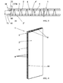
- This connecting armature 6 comprises, on the one hand, a first part 60 extending inside this wall 1 and, on the other hand, a second part 61, integral with the first part 60, extending to the outside of this wall 1, laterally with respect to the edge 10 of this wall 1 and in the extension of the internal volume 3 thereof 1.
- such a connecting armature 6 can equip a wall 1 integrated formwork both at its side edge 10 (as shown in the accompanying figures) at its longitudinal edge (especially at its level). upper longitudinal edge).
- At least the first part 60 of this connecting armature 6 is fixed relative to the wall 1 and extends inside this wall 1.
- FIG. 1 to 3 a first type of embodiment of such a connecting armature 6 having a first portion 60 and a second portion 61 fixed relative to the wall 1 while the Figures 4 to 9 illustrate a second embodiment comprising a first portion 60 fixed relative to the wall 1 and a second portion 61 movable relative thereto 1.
- the connecting armature 6 is constituted by a structure 7 at which the first part 60 of this connecting armature 6 is defined as well as the second part 61 of this armature 6.
- this connecting armature 6 extends internally to the wall 1, this at least inside the internal volume 3 of this wall 1 ( figure 3 ), or even within at least one skin (2; 2 ') of the wall 1, this being partially embedded in the material of such a skin (2; 2').
- this connecting armature 6 replaces, advantageously, an end beam that usually comprises an integrated form wall 1.
- such a connecting armature 6 comprises, on the one hand, a structure 7 constituting the first part 60 of this connecting armature 6, and extending at least inside the internal volume 3 of this wall 1.
- this structure 7 extends inside this internal volume 3 but also inside at least one skin (2; 2 ') of this wall 1, this being partly embedded in the material of such a skin (2; 2 ').
- this structure 7 replaces, advantageously, an end beam that usually comprises an integrated form wall 1.
- the connecting armature 6 corresponding to this second type of embodiment comprises, on the other hand, at least one element 8, associated with the structure 7, and constituting the second part 61 of this connecting armature 7.
- This element 8 is of mobile type relative to this structure 7, this between a retracted position at least partially inside the wall 1 ( Figures 5 and 8 ) and a deployed position outside this wall 1 ( Figures 7 and 9 ).
- such a movable element 8 is constituted by an elongated piece extending substantially perpendicular to the edge 10 of the wall 1 with respect to which this mobile element 8 extends.
- such an elongated piece may be constituted by a rod, by a pin 80 ( Figures 5 to 9 ) or the like.
- Such an elongate piece is constituted by a pin 80, it adopts a substantially "U" shape and is preferably defined from a rod, in particular by folding.
- this elongated piece is preferably made of a metallic material.
- connecting armature 6 comprises, again, at least one means 9, associated with the structure 7, and designed to ensure the displacement assembly of at least one element mobile 8.
- this connecting armature 6 comprises, for the same movable element 8, at least one pair of displacement mounting means (9; 9 ').
- this connecting armature 6 comprises a pair of displacement mounting means (9; 9 '), each mounting means (9; 9') being associated with a strand of the pin 80 in the shape of a "U".
- this connecting armature 6 comprises a pair of mounting means (9, 9a, 9 ', 9'a) associated with each strand of such a pin 80.
- Such an embodiment significantly facilitates the movement of the mobile element 8 with respect to the structure 7.
- such a displacement mounting means 9 is constituted by at least one guide means, more particularly in the form of a guide slide, in particular constituted by a hollow profile, preferably a hollow tube.
- This displacement mounting means 9 is preferably made of a metallic material and is then secured to the structure 7, preferably by welding.
- the connecting armature 6 comprises a plurality of movable elements 8.
- the connecting armature 6 may, again, comprise a means 11 for securing in movement these movable elements 8 relative to the structure 7.
- a securing means 11 may be constituted by at least one steel bar, especially high adhesion type.
- the connecting armature 6 is at least partially constituted by a structure 7.
- such a structure 7 is constituted by at least one basket 70 having bars 71, parallel to each other and arranged in a parallelogram (more particularly in a square, rectangle or other), and means 72 for connecting these bars 71 between they.
- Such bars 71 are preferably made of a metallic material, in particular steel.
- these may be constituted by rods (again metal) deformed (in particular by folding, more particularly to form a belt surrounding the bars 71) and connected to these bars 71 (preferably by welding).
- bars 71 of the basket 70 extend, on the one hand, parallel to the edge 10 of the wall 1 with respect to which the second portion 61 of the connecting armature 6 extends outwardly on the outside. wall 1 and, on the other hand, on at least part of the height ( Figures 1, 2 , 4 and 6 ) of the wall 1 or the length of the wall 1 (particularly at the upper end of the wall 1).
Landscapes
- Engineering & Computer Science (AREA)
- Architecture (AREA)
- Physics & Mathematics (AREA)
- Electromagnetism (AREA)
- Civil Engineering (AREA)
- Structural Engineering (AREA)
- Forms Removed On Construction Sites Or Auxiliary Members Thereof (AREA)
- Building Environments (AREA)
Priority Applications (1)
| Application Number | Priority Date | Filing Date | Title |
|---|---|---|---|
| EP20100305798 EP2410100B1 (de) | 2010-07-19 | 2010-07-19 | Mauer mit Verschalung, die mit einer Verbindungsbewehrung eingebaut ist |
Applications Claiming Priority (1)
| Application Number | Priority Date | Filing Date | Title |
|---|---|---|---|
| EP20100305798 EP2410100B1 (de) | 2010-07-19 | 2010-07-19 | Mauer mit Verschalung, die mit einer Verbindungsbewehrung eingebaut ist |
Publications (2)
| Publication Number | Publication Date |
|---|---|
| EP2410100A1 true EP2410100A1 (de) | 2012-01-25 |
| EP2410100B1 EP2410100B1 (de) | 2014-10-01 |
Family
ID=43567554
Family Applications (1)
| Application Number | Title | Priority Date | Filing Date |
|---|---|---|---|
| EP20100305798 Not-in-force EP2410100B1 (de) | 2010-07-19 | 2010-07-19 | Mauer mit Verschalung, die mit einer Verbindungsbewehrung eingebaut ist |
Country Status (1)
| Country | Link |
|---|---|
| EP (1) | EP2410100B1 (de) |
Cited By (2)
| Publication number | Priority date | Publication date | Assignee | Title |
|---|---|---|---|---|
| EP2792805A1 (de) * | 2013-04-15 | 2014-10-22 | Kappema Fertigteilindustrie GmbH | Wandbauteil bestehend aus Halbfertig-Bauteilen |
| US11248383B2 (en) | 2018-09-21 | 2022-02-15 | Cooper E. Stewart | Insulating concrete form apparatus |
Citations (2)
| Publication number | Priority date | Publication date | Assignee | Title |
|---|---|---|---|---|
| DE2139197A1 (de) | 1971-08-05 | 1973-02-22 | Konrad Schweiker | Bauelement mit einer verlorenen schalung |
| GB2444637A (en) | 2006-12-05 | 2008-06-11 | Liam Campion | Permanent formwork having with hollow concrete walls, separated and reinforced by steel framework |
-
2010
- 2010-07-19 EP EP20100305798 patent/EP2410100B1/de not_active Not-in-force
Patent Citations (2)
| Publication number | Priority date | Publication date | Assignee | Title |
|---|---|---|---|---|
| DE2139197A1 (de) | 1971-08-05 | 1973-02-22 | Konrad Schweiker | Bauelement mit einer verlorenen schalung |
| GB2444637A (en) | 2006-12-05 | 2008-06-11 | Liam Campion | Permanent formwork having with hollow concrete walls, separated and reinforced by steel framework |
Cited By (2)
| Publication number | Priority date | Publication date | Assignee | Title |
|---|---|---|---|---|
| EP2792805A1 (de) * | 2013-04-15 | 2014-10-22 | Kappema Fertigteilindustrie GmbH | Wandbauteil bestehend aus Halbfertig-Bauteilen |
| US11248383B2 (en) | 2018-09-21 | 2022-02-15 | Cooper E. Stewart | Insulating concrete form apparatus |
Also Published As
| Publication number | Publication date |
|---|---|
| EP2410100B1 (de) | 2014-10-01 |
Similar Documents
| Publication | Publication Date | Title |
|---|---|---|
| FR2942824A1 (fr) | Mur a coffrage integre avec armature de liaison | |
| EP2439352B1 (de) | Mauer mit verlorener Schalung und Verbindungsleine | |
| EP2495375B1 (de) | Integrierte wandschalung mit einem mobilen schwenkbarem verbindungselement | |
| EP3492675B1 (de) | Vorrichtung zum befestigen von lamellen an einem starren gitterpaneel, lamellenbefestigungskit an einem starren gitterpaneel und sichtschutzzaun, der mit diesem kit ausgestattet ist | |
| FR2917912A1 (fr) | Dispositif de cheminement de cables destine plus particulieremenet au cheminement et a la distribution de cables electriques | |
| EP3359744B1 (de) | Gründungsbauwerk | |
| EP2873781B1 (de) | Mauer mit verlorener Schalung mit steifen Verbindungsmitteln | |
| EP2410100B1 (de) | Mauer mit Verschalung, die mit einer Verbindungsbewehrung eingebaut ist | |
| EP3296481B1 (de) | Vorgefertigtes wand mit integrierter schalung | |
| EP2550406A1 (de) | Gebäude mit verstärktem fundament | |
| EP2402531A2 (de) | Vorgefertige Betontreppe mit modularer Treppenwange | |
| EP2628869B1 (de) | Vorrichtung zur Verbindung von Fertigtteile zum Errichten eines Gebäudes | |
| FR2922235A1 (fr) | Bande de stabilisation destinee a etre utilisee dans des ouvrages en sol renforce | |
| FR2927105A1 (fr) | Mur a coffrage perdu comportant un moyen de raccordement a un engin de manutention | |
| EP3061880B1 (de) | Fertigbalkon mit rippen | |
| EP2899327B1 (de) | Dämmendes Bauelement und sein Herstellungsverfahren | |
| EP3061881A1 (de) | Gerippter Fertigbalkon | |
| EP2944734B1 (de) | Dämmwand mit einem in dieselbe haut eingelassenen hebeband | |
| EP2283185B9 (de) | Stabilisierungsbewehrung zur verwendung in bewehrten bodenkonstruktionen | |
| EP2944735B1 (de) | Dämmwand mit angebrachten Hebebändern | |
| FR2998314A1 (fr) | Dispositif de maintien des fers de renfort dans une structure de banchage d'une paroi | |
| FR2938569A1 (fr) | Mur prefabrique equipe d'un dispositif de mise en place d'un garde-corps | |
| WO2021239644A1 (fr) | Element d'armatures pour paroi moulee muni d'un porte-joint d'etancheite | |
| EP1812662B1 (de) | Schalungselement zur herstellung einer verstärkten formplatte und durch zusammenbau der elemente erhaltbare schalungsstruktur | |
| FR2940337A1 (fr) | Poutrelle metallique pour la fabrication de planchers |
Legal Events
| Date | Code | Title | Description |
|---|---|---|---|
| AK | Designated contracting states |
Kind code of ref document: A1 Designated state(s): AL AT BE BG CH CY CZ DE DK EE ES FI FR GB GR HR HU IE IS IT LI LT LU LV MC MK MT NL NO PL PT RO SE SI SK SM TR |
|
| AX | Request for extension of the european patent |
Extension state: BA ME RS |
|
| PUAI | Public reference made under article 153(3) epc to a published international application that has entered the european phase |
Free format text: ORIGINAL CODE: 0009012 |
|
| 17P | Request for examination filed |
Effective date: 20120618 |
|
| 17Q | First examination report despatched |
Effective date: 20130829 |
|
| GRAP | Despatch of communication of intention to grant a patent |
Free format text: ORIGINAL CODE: EPIDOSNIGR1 |
|
| INTG | Intention to grant announced |
Effective date: 20140411 |
|
| GRAS | Grant fee paid |
Free format text: ORIGINAL CODE: EPIDOSNIGR3 |
|
| GRAA | (expected) grant |
Free format text: ORIGINAL CODE: 0009210 |
|
| RAP1 | Party data changed (applicant data changed or rights of an application transferred) |
Owner name: FEHR GROUPE |
|
| AK | Designated contracting states |
Kind code of ref document: B1 Designated state(s): AL AT BE BG CH CY CZ DE DK EE ES FI FR GB GR HR HU IE IS IT LI LT LU LV MC MK MT NL NO PL PT RO SE SI SK SM TR |
|
| REG | Reference to a national code |
Ref country code: GB Ref legal event code: FG4D Free format text: NOT ENGLISH |
|
| REG | Reference to a national code |
Ref country code: AT Ref legal event code: REF Ref document number: 689639 Country of ref document: AT Kind code of ref document: T Effective date: 20141015 Ref country code: CH Ref legal event code: EP |
|
| REG | Reference to a national code |
Ref country code: IE Ref legal event code: FG4D Free format text: LANGUAGE OF EP DOCUMENT: FRENCH |
|
| REG | Reference to a national code |
Ref country code: DE Ref legal event code: R096 Ref document number: 602010019220 Country of ref document: DE Effective date: 20141113 |
|
| REG | Reference to a national code |
Ref country code: NL Ref legal event code: VDEP Effective date: 20141001 |
|
| REG | Reference to a national code |
Ref country code: AT Ref legal event code: MK05 Ref document number: 689639 Country of ref document: AT Kind code of ref document: T Effective date: 20141001 |
|
| REG | Reference to a national code |
Ref country code: LT Ref legal event code: MG4D |
|
| PG25 | Lapsed in a contracting state [announced via postgrant information from national office to epo] |
Ref country code: NL Free format text: LAPSE BECAUSE OF FAILURE TO SUBMIT A TRANSLATION OF THE DESCRIPTION OR TO PAY THE FEE WITHIN THE PRESCRIBED TIME-LIMIT Effective date: 20141001 |
|
| PG25 | Lapsed in a contracting state [announced via postgrant information from national office to epo] |
Ref country code: CZ Free format text: LAPSE BECAUSE OF FAILURE TO SUBMIT A TRANSLATION OF THE DESCRIPTION OR TO PAY THE FEE WITHIN THE PRESCRIBED TIME-LIMIT Effective date: 20141001 Ref country code: ES Free format text: LAPSE BECAUSE OF FAILURE TO SUBMIT A TRANSLATION OF THE DESCRIPTION OR TO PAY THE FEE WITHIN THE PRESCRIBED TIME-LIMIT Effective date: 20141001 Ref country code: PT Free format text: LAPSE BECAUSE OF FAILURE TO SUBMIT A TRANSLATION OF THE DESCRIPTION OR TO PAY THE FEE WITHIN THE PRESCRIBED TIME-LIMIT Effective date: 20150202 Ref country code: NO Free format text: LAPSE BECAUSE OF FAILURE TO SUBMIT A TRANSLATION OF THE DESCRIPTION OR TO PAY THE FEE WITHIN THE PRESCRIBED TIME-LIMIT Effective date: 20150101 Ref country code: FI Free format text: LAPSE BECAUSE OF FAILURE TO SUBMIT A TRANSLATION OF THE DESCRIPTION OR TO PAY THE FEE WITHIN THE PRESCRIBED TIME-LIMIT Effective date: 20141001 Ref country code: IS Free format text: LAPSE BECAUSE OF FAILURE TO SUBMIT A TRANSLATION OF THE DESCRIPTION OR TO PAY THE FEE WITHIN THE PRESCRIBED TIME-LIMIT Effective date: 20150201 Ref country code: LT Free format text: LAPSE BECAUSE OF FAILURE TO SUBMIT A TRANSLATION OF THE DESCRIPTION OR TO PAY THE FEE WITHIN THE PRESCRIBED TIME-LIMIT Effective date: 20141001 |
|
| PG25 | Lapsed in a contracting state [announced via postgrant information from national office to epo] |
Ref country code: GR Free format text: LAPSE BECAUSE OF FAILURE TO SUBMIT A TRANSLATION OF THE DESCRIPTION OR TO PAY THE FEE WITHIN THE PRESCRIBED TIME-LIMIT Effective date: 20150102 Ref country code: CY Free format text: LAPSE BECAUSE OF FAILURE TO SUBMIT A TRANSLATION OF THE DESCRIPTION OR TO PAY THE FEE WITHIN THE PRESCRIBED TIME-LIMIT Effective date: 20141001 Ref country code: HR Free format text: LAPSE BECAUSE OF FAILURE TO SUBMIT A TRANSLATION OF THE DESCRIPTION OR TO PAY THE FEE WITHIN THE PRESCRIBED TIME-LIMIT Effective date: 20141001 Ref country code: AT Free format text: LAPSE BECAUSE OF FAILURE TO SUBMIT A TRANSLATION OF THE DESCRIPTION OR TO PAY THE FEE WITHIN THE PRESCRIBED TIME-LIMIT Effective date: 20141001 Ref country code: SE Free format text: LAPSE BECAUSE OF FAILURE TO SUBMIT A TRANSLATION OF THE DESCRIPTION OR TO PAY THE FEE WITHIN THE PRESCRIBED TIME-LIMIT Effective date: 20141001 Ref country code: LV Free format text: LAPSE BECAUSE OF FAILURE TO SUBMIT A TRANSLATION OF THE DESCRIPTION OR TO PAY THE FEE WITHIN THE PRESCRIBED TIME-LIMIT Effective date: 20141001 Ref country code: PL Free format text: LAPSE BECAUSE OF FAILURE TO SUBMIT A TRANSLATION OF THE DESCRIPTION OR TO PAY THE FEE WITHIN THE PRESCRIBED TIME-LIMIT Effective date: 20141001 |
|
| REG | Reference to a national code |
Ref country code: DE Ref legal event code: R097 Ref document number: 602010019220 Country of ref document: DE |
|
| REG | Reference to a national code |
Ref country code: DE Ref legal event code: R082 Ref document number: 602010019220 Country of ref document: DE Representative=s name: PATENTANWAELTE UND RECHTSANWALT DR. WEISS, ARA, DE Ref country code: DE Ref legal event code: R082 Ref document number: 602010019220 Country of ref document: DE Representative=s name: PATENTANWAELTE UND RECHTSANWALT WEISS, ARAT & , DE |
|
| PG25 | Lapsed in a contracting state [announced via postgrant information from national office to epo] |
Ref country code: SK Free format text: LAPSE BECAUSE OF FAILURE TO SUBMIT A TRANSLATION OF THE DESCRIPTION OR TO PAY THE FEE WITHIN THE PRESCRIBED TIME-LIMIT Effective date: 20141001 Ref country code: RO Free format text: LAPSE BECAUSE OF FAILURE TO SUBMIT A TRANSLATION OF THE DESCRIPTION OR TO PAY THE FEE WITHIN THE PRESCRIBED TIME-LIMIT Effective date: 20141001 Ref country code: EE Free format text: LAPSE BECAUSE OF FAILURE TO SUBMIT A TRANSLATION OF THE DESCRIPTION OR TO PAY THE FEE WITHIN THE PRESCRIBED TIME-LIMIT Effective date: 20141001 Ref country code: DK Free format text: LAPSE BECAUSE OF FAILURE TO SUBMIT A TRANSLATION OF THE DESCRIPTION OR TO PAY THE FEE WITHIN THE PRESCRIBED TIME-LIMIT Effective date: 20141001 |
|
| PLBE | No opposition filed within time limit |
Free format text: ORIGINAL CODE: 0009261 |
|
| STAA | Information on the status of an ep patent application or granted ep patent |
Free format text: STATUS: NO OPPOSITION FILED WITHIN TIME LIMIT |
|
| PG25 | Lapsed in a contracting state [announced via postgrant information from national office to epo] |
Ref country code: IT Free format text: LAPSE BECAUSE OF FAILURE TO SUBMIT A TRANSLATION OF THE DESCRIPTION OR TO PAY THE FEE WITHIN THE PRESCRIBED TIME-LIMIT Effective date: 20141001 |
|
| PGFP | Annual fee paid to national office [announced via postgrant information from national office to epo] |
Ref country code: LU Payment date: 20150724 Year of fee payment: 6 |
|
| 26N | No opposition filed |
Effective date: 20150702 |
|
| PGFP | Annual fee paid to national office [announced via postgrant information from national office to epo] |
Ref country code: IE Payment date: 20150723 Year of fee payment: 6 Ref country code: CH Payment date: 20150721 Year of fee payment: 6 Ref country code: DE Payment date: 20150721 Year of fee payment: 6 Ref country code: MC Payment date: 20150714 Year of fee payment: 6 Ref country code: GB Payment date: 20150721 Year of fee payment: 6 |
|
| PGFP | Annual fee paid to national office [announced via postgrant information from national office to epo] |
Ref country code: BE Payment date: 20150721 Year of fee payment: 6 |
|
| PG25 | Lapsed in a contracting state [announced via postgrant information from national office to epo] |
Ref country code: SI Free format text: LAPSE BECAUSE OF FAILURE TO SUBMIT A TRANSLATION OF THE DESCRIPTION OR TO PAY THE FEE WITHIN THE PRESCRIBED TIME-LIMIT Effective date: 20141001 |
|
| REG | Reference to a national code |
Ref country code: FR Ref legal event code: PLFP Year of fee payment: 7 |
|
| PG25 | Lapsed in a contracting state [announced via postgrant information from national office to epo] |
Ref country code: BE Free format text: LAPSE BECAUSE OF NON-PAYMENT OF DUE FEES Effective date: 20160731 |
|
| REG | Reference to a national code |
Ref country code: DE Ref legal event code: R119 Ref document number: 602010019220 Country of ref document: DE |
|
| REG | Reference to a national code |
Ref country code: CH Ref legal event code: PL |
|
| GBPC | Gb: european patent ceased through non-payment of renewal fee |
Effective date: 20160719 |
|
| PG25 | Lapsed in a contracting state [announced via postgrant information from national office to epo] |
Ref country code: MT Free format text: LAPSE BECAUSE OF FAILURE TO SUBMIT A TRANSLATION OF THE DESCRIPTION OR TO PAY THE FEE WITHIN THE PRESCRIBED TIME-LIMIT Effective date: 20141001 Ref country code: MC Free format text: LAPSE BECAUSE OF NON-PAYMENT OF DUE FEES Effective date: 20160801 |
|
| PG25 | Lapsed in a contracting state [announced via postgrant information from national office to epo] |
Ref country code: CH Free format text: LAPSE BECAUSE OF NON-PAYMENT OF DUE FEES Effective date: 20160731 Ref country code: DE Free format text: LAPSE BECAUSE OF NON-PAYMENT OF DUE FEES Effective date: 20170201 Ref country code: LI Free format text: LAPSE BECAUSE OF NON-PAYMENT OF DUE FEES Effective date: 20160731 |
|
| REG | Reference to a national code |
Ref country code: IE Ref legal event code: MM4A |
|
| PG25 | Lapsed in a contracting state [announced via postgrant information from national office to epo] |
Ref country code: GB Free format text: LAPSE BECAUSE OF NON-PAYMENT OF DUE FEES Effective date: 20160719 Ref country code: HU Free format text: LAPSE BECAUSE OF FAILURE TO SUBMIT A TRANSLATION OF THE DESCRIPTION OR TO PAY THE FEE WITHIN THE PRESCRIBED TIME-LIMIT; INVALID AB INITIO Effective date: 20100719 Ref country code: SM Free format text: LAPSE BECAUSE OF FAILURE TO SUBMIT A TRANSLATION OF THE DESCRIPTION OR TO PAY THE FEE WITHIN THE PRESCRIBED TIME-LIMIT Effective date: 20141001 Ref country code: BG Free format text: LAPSE BECAUSE OF FAILURE TO SUBMIT A TRANSLATION OF THE DESCRIPTION OR TO PAY THE FEE WITHIN THE PRESCRIBED TIME-LIMIT Effective date: 20141001 |
|
| REG | Reference to a national code |
Ref country code: FR Ref legal event code: PLFP Year of fee payment: 8 |
|
| PG25 | Lapsed in a contracting state [announced via postgrant information from national office to epo] |
Ref country code: IE Free format text: LAPSE BECAUSE OF NON-PAYMENT OF DUE FEES Effective date: 20160719 |
|
| PG25 | Lapsed in a contracting state [announced via postgrant information from national office to epo] |
Ref country code: TR Free format text: LAPSE BECAUSE OF FAILURE TO SUBMIT A TRANSLATION OF THE DESCRIPTION OR TO PAY THE FEE WITHIN THE PRESCRIBED TIME-LIMIT Effective date: 20141001 Ref country code: LU Free format text: LAPSE BECAUSE OF NON-PAYMENT OF DUE FEES Effective date: 20160719 |
|
| PG25 | Lapsed in a contracting state [announced via postgrant information from national office to epo] |
Ref country code: MK Free format text: LAPSE BECAUSE OF FAILURE TO SUBMIT A TRANSLATION OF THE DESCRIPTION OR TO PAY THE FEE WITHIN THE PRESCRIBED TIME-LIMIT Effective date: 20141001 |
|
| REG | Reference to a national code |
Ref country code: FR Ref legal event code: PLFP Year of fee payment: 9 |
|
| PG25 | Lapsed in a contracting state [announced via postgrant information from national office to epo] |
Ref country code: AL Free format text: LAPSE BECAUSE OF FAILURE TO SUBMIT A TRANSLATION OF THE DESCRIPTION OR TO PAY THE FEE WITHIN THE PRESCRIBED TIME-LIMIT Effective date: 20141001 |
|
| PGFP | Annual fee paid to national office [announced via postgrant information from national office to epo] |
Ref country code: FR Payment date: 20210720 Year of fee payment: 12 |
|
| PG25 | Lapsed in a contracting state [announced via postgrant information from national office to epo] |
Ref country code: FR Free format text: LAPSE BECAUSE OF NON-PAYMENT OF DUE FEES Effective date: 20220731 |