EP2410110A2 - Cylindre de fermeture, notamment cylindre double doté d'un organe de fermeture à roue libre - Google Patents
Cylindre de fermeture, notamment cylindre double doté d'un organe de fermeture à roue libre Download PDFInfo
- Publication number
- EP2410110A2 EP2410110A2 EP11173018A EP11173018A EP2410110A2 EP 2410110 A2 EP2410110 A2 EP 2410110A2 EP 11173018 A EP11173018 A EP 11173018A EP 11173018 A EP11173018 A EP 11173018A EP 2410110 A2 EP2410110 A2 EP 2410110A2
- Authority
- EP
- European Patent Office
- Prior art keywords
- coupling
- coupling element
- key
- cylinder
- closing member
- Prior art date
- Legal status (The legal status is an assumption and is not a legal conclusion. Google has not performed a legal analysis and makes no representation as to the accuracy of the status listed.)
- Granted
Links
Images








Classifications
-
- E—FIXED CONSTRUCTIONS
- E05—LOCKS; KEYS; WINDOW OR DOOR FITTINGS; SAFES
- E05B—LOCKS; ACCESSORIES THEREFOR; HANDCUFFS
- E05B9/00—Lock casings or latch-mechanism casings ; Fastening locks or fasteners or parts thereof to the wing
- E05B9/04—Casings of cylinder locks
- E05B9/045—Modular casings for adjusting the length of cylinder locks
-
- E—FIXED CONSTRUCTIONS
- E05—LOCKS; KEYS; WINDOW OR DOOR FITTINGS; SAFES
- E05B—LOCKS; ACCESSORIES THEREFOR; HANDCUFFS
- E05B9/00—Lock casings or latch-mechanism casings ; Fastening locks or fasteners or parts thereof to the wing
- E05B9/10—Coupling devices for the two halves of double cylinder locks, e.g. devices for coupling the rotor with the locking cam
Definitions
- the invention relates to a lock cylinder, in particular a equipped with a free-running closing member double lock cylinder with a housing, a rotatably mounted in a bearing cavity of the housing cylinder core, which by means of a displaceable when inserting a key into a keyway of the cylinder core of the key tip in a coupling position coupling member the closure member can be coupled, in which coupling position engages a coupling projection of the coupling member in a coupling recess associated therewith of the closing member, wherein the coupling member exits when the key is removed by applying a torque to the closing member from the coupling position.
- the lock cylinder according to the invention particularly relates to a double lock cylinder, as he from the DE 10 2009 038 229 A1 is already known.
- the lock cylinder described therein has a two-part housing, wherein each housing half forms a bearing cavity in which a cylinder core is rotatably mounted. If the key is not inserted, the cylinder core is locked in rotation by means of tumbler pins. These are displaced by insertion of a suitable key in a release position, so that the rotational lock of the cylinder core is released and the cylinder core can be rotated.
- the tip of the key acts on a coupling member which has coupling projections which can enter into coupling recesses of the closure member by sliding the coupling member towards a closing member to rotatably couple the closure member to the cylinder core to rotate upon rotation of the key Cylinder core is dragged.
- the coupling member is spring-loaded in the direction of the cylinder core.
- a control pin engages in a control recess with inclined edges. If a torque is applied to the coupling member via the closing member, then the control pin can slide along the inclined edge and controls the closing member from its coupling position.
- the invention is based on the object to improve a lock cylinder with simple means closing technology.
- an oblique edge control of the torque transmission flanks adjacent to one another in the coupling position is provided in order to displace the coupling member from the coupling position when the closing member is subjected to a torque when the key is removed.
- Either the coupling projection or the coupling recess or both have torque transmitting flanks forming an inclined surface. If a torque is applied to this inclined surface, then arises a force directed in the axial direction in the direction away from the closing member, which displaces the coupling member out of the coupling position.
- a development of the invention which has an independent character, provides that the coupling member is floatingly mounted in a bearing cavity of the cylinder core. According to this embodiment, it is possible to dispense with the return spring provided in the prior art, which displaces the coupling member from the coupling position.
- the torque transmission surfaces can form gradient surfaces.
- the pitch surfaces have a pitch angle that cause no self-locking of the axially displaceable coupling elements.
- the torque transmission surfaces are preferably formed by worm thread pitch surfaces. It can be provided from a facing the closing member end face of the coupling member projecting, extending on different circular arc sections coupling projections.
- first coupling element which is coupled rotationally fixed and axially displaceable with the cylinder core.
- first coupling element can have one or two radially projecting ribs which lie in corresponding axial slots of the cylinder core.
- the first coupling element may have a cup-like receiving cavity, the opening of which is directed towards the closing member.
- a second coupling element is mounted, which has the coupling projection or preferably the two coupling projections.
- a compression spring is provided between the first coupling element and the second coupling element which unfolds a spring force, with which the two coupling element are spread apart in the axial direction.
- Fesselungs provided in the form of pins to tie the second coupling element in therachöhlung.
- the pins pass through holes in the pot wall of the first coupling element and engage in peripheral recesses of the second coupling element.
- the spring is supported on the one hand on the bottom of the pot and on the other hand in an end-side annular cavity of the second coupling element. From the bottom or the frontal cavity centering can go out, which protrude into the compression spring. Is the insertion of the key, the coupling recess of the closing member is not in an alignment with the coupling projection, the first coupling element can nevertheless be displaced axially from the key tip. Since the coupling projection of the second coupling element can not enter into its associated Kupplungsaus predominantlyung, the second coupling element can not be mitverlagert. This leads to a compression of the Feather.
- the cylinder core can be rotated until the coupling projection reaches its escape position to the coupling recess.
- the tensioned spring then displaces the second coupling element in the coupling position.
- blocking elements are provided which block each relative displacement to each other with a slight relative rotation of the two coupling elements. This has the consequence that in this relative displacement, the second coupling element can no longer move relative to the first coupling element.
- the lock cylinder according to the invention has tumbler pins, which cooperates with mounted on the key broad side of the key Codungsmulden.
- the key is a reversible flat key. Furthermore, the manipulation of the closing member is made more difficult, since the bearing cavity of the cylinder core is filled with the diametrical wall slots through the closed surface of the first coupling member.
- the acted upon by the key tip end face of the lock cylinder is preferably a plane surface. It is designed so that the opening of the keyway is opened in the direction of the closing member of the coupling element.
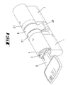
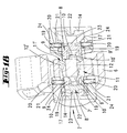
- the lock cylinder shown in the drawings consists of two cylinder housing halves 1, which are connected together by a connecting web 29 to a one-piece housing.
- the axial length of the housing can be changed by one or more extension pieces 27.
- the use of the individual housing elements 1, 27, 29 takes place by means of fastening screws 30.
- Each of the two cylinder housing halves 1 forms a bearing cavity 2.
- the two storage cavities 2 are aligned.
- a closing member 6 Between the bearing cavities 2 of the two cylinder housing halves 1 is a closing member 6, which is rotatable.
- stuck cylinder cores 3 In the two storage cavities 2 stuck cylinder cores 3, which are held there by retaining rings 28.
- This cylinder core 3 has a key channel 4 for inserting a key. 5
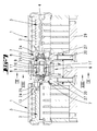
- the cylinder core 3 has in the region of an end facing the closing member 6 a bearing cavity 26 for receiving a first coupling element 7.
- the bearing cavity 26 has diametral wall slots 25, engage in the radially projecting, different width ribs 24 of the first coupling member 7.
- the coupling element 7 is characterized rotationally fixed and radially bearing-oriented but axially displaceable tied to the cylinder core 3.
- the first coupling element 7 forms together with a second coupling element 8, a coupling member to the cylinder core 3 against rotation of the To lock closing member 6 so that the closing member 6 can be dragged in a key-operated rotation of the cylinder core 3.
- the first coupling element 7 has a cup-shaped receiving cavity, in which the second coupling element 8 is receiving. From the bottom of the receiving cavity 14 projects from a centering pin 20 which is a centering pin 23 of a Stirn dioxideung the second coupling element 8 opposite. On the two pins 22, 23 is inserted in each case one end of a compression spring 13, with which the two coupling elements 7, 8 are acted upon each other away.
- the wall of the recess 14 has two opposing bores 21, in which tethering pins stuck 20 which enter into FesselungsausEnglishept 19 of the outer edge of the second coupling element 8 to tie the two coupling elements 7, 8 to each other.
- a beveled blocking stage 15 In the region of the wall of the receiving cavity 14 is a beveled blocking stage 15.
- the blocking stage 15 is flanked by two angular edges 16.
- the two angular edges In the in the FIGS. 8 to 12 shown operating positions extends a transition edge of a flat edge 18 to the end edge 17 of the second coupling element 8 parallel to the extension direction of the blocking stage 15. In this operating position, the two angular edges are spaced from the flat side edge 18. If an axial force is applied to the second coupling element 8 in the direction of the first coupling element 7 in this position, the second coupling element 8 can dip into the receiving cavity 14.
- the planar flank 18 slides along the blocking stage 15.
- the spring 13 is compressed. It can be in the Figures 17 and 18 left illustrated operating position of the two coupling elements 7, 8 formed coupling member can be achieved.
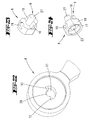
- the second coupling element 8 has two from its facing the closing member 6 end face projecting coupling projections 9, 9 '.
- the exemplary embodiment involves area-like torque-transmitting flanks 10, 10 ', which rest in a coupling position on corresponding torque transmission surfaces 12, 12', which are formed by the narrow side surfaces of arcuate coupling recesses 11, 11 'of the closing member 6.
- the torque transmitting surfaces 12, 12 ', 9, 9' are designed so that a torque which is exerted by the closing member 6 on the second coupling element 8, exerts an axial force on the second coupling element 8.
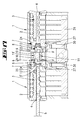
- the operation of the lock cylinder is the following: Starting from the in FIG. 7 shown operating position in which the coupling projections 9, 9 'of both coupling members 7, 8 are in alignment with the coupling recesses 11, 11' of the closing member 6 in the keyway 4 of the right cylinder core 3 inserted a matching key, so his key tip 5 'by attack on the flat surface 7 'of the first coupling element 8, the entire coupling member 7, 8 relocate such that the coupling projections 9, 9' in their associated coupling recesses 11, 11 'occur.
- the left cylinder core associated coupling member 7, 8 has an arbitrary operating state. In the in FIG. 7 shown position engage the coupling projections 9, 9 'in the coupling recess 11, 11' of the closing member 6 a. Since no key is inserted into the left cylinder core 3, the floating in the bearing opening 26 mounted coupling member 7, 8 is axially displaceable. Now, if the inserted into the right cylinder core 3 key is rotated, the torque transmission surfaces 10,10 ', 12, 12' of the left coupling member 7, 8 slide against each other.
- the coupling projections 9, 9 'of the right coupling member 7, 8, however, can not escape from the coupling recesses 11, 11', because the key inserted there locks a Axialverlager ein the first coupling element 7 and the second coupling element 8 according to the applied torque with respect to the first coupling element. 7 is motion blocked.
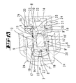
- the coupling projections 9 are formed by radially projecting from a central portion 17 of the second coupling element 8 pin.
- the torque transmission surfaces 10 are formed by the outer surface of the pins extending on a cylinder jacket surface.
- the closing member 6 has a form-fitting coupling recess 11 with a central portion 28 into which the central portion 27 can enter. From This central section is a total of four coupling recesses 11, each forming torque transmitting surfaces 12.
- the torque transmission surfaces 12 are the well surfaces of a trough-shaped trough.
- the individual coupling projections 9 have different diameters or lengths.
- the coupling recesses 11 also have different diameters and lengths.
- the coupling projection 9 also has a central portion 27.
- the coupling projection 9 extends in a semicircle around the central portion 27 and forms two oblique torque transmitting surfaces 10 from.
- the recess corresponding to the coupling projection 9 of the closing member 6 also forms a central portion 28, in which the central portion 27 can occur.
- the central portion 28 is flanked by an approximately semicircular coupling recess 11, the walls of which form oblique torque transmission surfaces 12.
- a central portion 27 is also provided in the form of a cylinder pin on the second coupling element 8, projecting from the jacket wall cosmic coupling projections 9 in the radial direction.
- roof-like torque transmitting surfaces 10 are provided to each other.
- the roof-like torque transmission surfaces 10 of the coupling projections 9 enter into corresponding coupling recesses 11 of the closing member 6, which lie relative to a central portion 28 diametrically opposite.
- the coupling projections 9 have a different shape, so that the second coupling element 8 can couple only in a single rotational position with the closing member 6.
- the closing member 6 has a corresponding to the central portion 27 cavity. From this central portion 28 of the cavity goes from a coupling recess 11, the curved torque transmission surfaces 12 forms.
Landscapes
- Engineering & Computer Science (AREA)
- Mechanical Engineering (AREA)
- Lock And Its Accessories (AREA)
- Lighting Device Outwards From Vehicle And Optical Signal (AREA)
- Preventing Unauthorised Actuation Of Valves (AREA)
Priority Applications (1)
| Application Number | Priority Date | Filing Date | Title |
|---|---|---|---|
| SI201131529T SI2410110T1 (en) | 2010-07-22 | 2011-07-07 | A lock cylinder, in particular a double cylinder lock with a free-flowing locking member |
Applications Claiming Priority (1)
| Application Number | Priority Date | Filing Date | Title |
|---|---|---|---|
| DE201010036573 DE102010036573A1 (de) | 2010-07-22 | 2010-07-22 | Schließzylinder, insbesondere Doppelschließzylinder mit freilaufendem Schließglied |
Publications (3)
| Publication Number | Publication Date |
|---|---|
| EP2410110A2 true EP2410110A2 (fr) | 2012-01-25 |
| EP2410110A3 EP2410110A3 (fr) | 2014-11-05 |
| EP2410110B1 EP2410110B1 (fr) | 2018-05-09 |
Family
ID=44800378
Family Applications (1)
| Application Number | Title | Priority Date | Filing Date |
|---|---|---|---|
| EP11173018.0A Active EP2410110B1 (fr) | 2010-07-22 | 2011-07-07 | Cylindre de fermeture, notamment cylindre double doté d'un organe de fermeture à roue libre |
Country Status (4)
| Country | Link |
|---|---|
| EP (1) | EP2410110B1 (fr) |
| DE (1) | DE102010036573A1 (fr) |
| ES (1) | ES2669178T3 (fr) |
| SI (1) | SI2410110T1 (fr) |
Cited By (6)
| Publication number | Priority date | Publication date | Assignee | Title |
|---|---|---|---|---|
| ES2426340A1 (es) * | 2013-07-19 | 2013-10-22 | La Industria Cerrajera, S.A. | Cilindro de cierre provisto de puente de conexión |
| CZ305669B6 (cs) * | 2014-11-06 | 2016-01-27 | Tokoz A.S. | Spojka pro oboustranný válcový zámek |
| WO2016150258A1 (fr) * | 2015-03-24 | 2016-09-29 | 朱嘉斌 | Procédé de commande et de décodage réciproque de barillet de serrure double pour serrure et serrure à commande réciproque à barillet double |
| CZ306920B6 (cs) * | 2016-07-18 | 2017-09-13 | Tokoz A.S. | Spojka pro oboustranný válcový zámek |
| EP2628874A3 (fr) * | 2012-02-17 | 2018-01-24 | ABUS August Bremicker Söhne KG | Cylindre de fermeture |
| CZ310175B6 (cs) * | 2023-07-24 | 2024-10-23 | TOKOZ a.s | Spojka pro oboustranný válcový zámek a oboustranný válcový zámek s touto spojkou |
Citations (1)
| Publication number | Priority date | Publication date | Assignee | Title |
|---|---|---|---|---|
| DE102009038229A1 (de) | 2008-10-09 | 2010-04-15 | Kaba Gmbh | Schließzylinder |
Family Cites Families (2)
| Publication number | Priority date | Publication date | Assignee | Title |
|---|---|---|---|---|
| DE3630602A1 (de) * | 1986-09-09 | 1987-10-08 | Esfira Efune | Sicherheitsschloss mit beidseitigen schliessbaren doppelzylindern |
| FR2775716B1 (fr) * | 1998-03-05 | 2000-05-19 | Vachette Sa | Cylindre de surete a barillet double |
-
2010
- 2010-07-22 DE DE201010036573 patent/DE102010036573A1/de not_active Withdrawn
-
2011
- 2011-07-07 ES ES11173018.0T patent/ES2669178T3/es active Active
- 2011-07-07 SI SI201131529T patent/SI2410110T1/en unknown
- 2011-07-07 EP EP11173018.0A patent/EP2410110B1/fr active Active
Patent Citations (1)
| Publication number | Priority date | Publication date | Assignee | Title |
|---|---|---|---|---|
| DE102009038229A1 (de) | 2008-10-09 | 2010-04-15 | Kaba Gmbh | Schließzylinder |
Cited By (8)
| Publication number | Priority date | Publication date | Assignee | Title |
|---|---|---|---|---|
| EP2628874A3 (fr) * | 2012-02-17 | 2018-01-24 | ABUS August Bremicker Söhne KG | Cylindre de fermeture |
| ES2426340A1 (es) * | 2013-07-19 | 2013-10-22 | La Industria Cerrajera, S.A. | Cilindro de cierre provisto de puente de conexión |
| EP2826933A3 (fr) * | 2013-07-19 | 2016-02-24 | La Industrial Cerrajera S.A. | Serrure cylindrique équipé d'un pont de liaison |
| CZ305669B6 (cs) * | 2014-11-06 | 2016-01-27 | Tokoz A.S. | Spojka pro oboustranný válcový zámek |
| WO2016150258A1 (fr) * | 2015-03-24 | 2016-09-29 | 朱嘉斌 | Procédé de commande et de décodage réciproque de barillet de serrure double pour serrure et serrure à commande réciproque à barillet double |
| US10900257B2 (en) | 2015-03-24 | 2021-01-26 | Kapan CHU | Method for mutually controlling and unlocking a dual plug in a lock and a lock with a dual plug |
| CZ306920B6 (cs) * | 2016-07-18 | 2017-09-13 | Tokoz A.S. | Spojka pro oboustranný válcový zámek |
| CZ310175B6 (cs) * | 2023-07-24 | 2024-10-23 | TOKOZ a.s | Spojka pro oboustranný válcový zámek a oboustranný válcový zámek s touto spojkou |
Also Published As
| Publication number | Publication date |
|---|---|
| SI2410110T1 (en) | 2018-08-31 |
| ES2669178T3 (es) | 2018-05-24 |
| EP2410110A3 (fr) | 2014-11-05 |
| DE102010036573A1 (de) | 2012-01-26 |
| EP2410110B1 (fr) | 2018-05-09 |
Similar Documents
| Publication | Publication Date | Title |
|---|---|---|
| DE69713087T2 (de) | Auswechselbarer schliesszylinder | |
| EP2410110B1 (fr) | Cylindre de fermeture, notamment cylindre double doté d'un organe de fermeture à roue libre | |
| DE3838481A1 (de) | Zylinderschloss | |
| WO2022073854A1 (fr) | Kit d'assemblage de base de cadenas et système de cadenas | |
| DE102009030032A1 (de) | Plättchenzylinder mit sperrbaren Plättchenzuhaltungen | |
| DE102012003168A1 (de) | Schliesszylinder | |
| EP2218850B1 (fr) | Système de verrouillage avec dispositif de couplage pour un cylindre de fermeture double doté d'une fonction d'urgence et de danger contenant deux rotors, et avec clé associée | |
| DE2905941A1 (de) | Steuereinrichtung, insbesondere schloss | |
| EP2792822B1 (fr) | Codage via des poutres de blocage | |
| EP3205796B1 (fr) | Clé pour un barillet, barillet et dispositif de fermeture | |
| EP2619387A1 (fr) | Cylindre de serrure rotatif et clé de sûreté | |
| DE202019102154U1 (de) | Modulartig aufgebauter Schließzylinder | |
| EP3620597A1 (fr) | Cylindre de fermeture | |
| DE102018131779A1 (de) | Schließvorrichtung | |
| CH680935A5 (fr) | ||
| EP1671001B1 (fr) | Serrure | |
| EP1724417B1 (fr) | Élément de serrure | |
| DE102005040161A1 (de) | Schließzylinder mit Fliehkraftbremse | |
| EP1700980B1 (fr) | Cylindre pour serrure de sécurité | |
| DE102015100469A1 (de) | Schließzylinder | |
| DE102007002975A1 (de) | Gefahrenschließzylinder | |
| EP3647516B1 (fr) | Cylindre de serrure | |
| EP0591661A2 (fr) | Serrure cylindrique à combinaision modifiable | |
| CH635647A5 (en) | Double-cylinder lock | |
| DE102005026930A1 (de) | Vorhangschloss |
Legal Events
| Date | Code | Title | Description |
|---|---|---|---|
| AK | Designated contracting states |
Kind code of ref document: A2 Designated state(s): AL AT BE BG CH CY CZ DE DK EE ES FI FR GB GR HR HU IE IS IT LI LT LU LV MC MK MT NL NO PL PT RO RS SE SI SK SM TR |
|
| AX | Request for extension of the european patent |
Extension state: BA ME |
|
| PUAI | Public reference made under article 153(3) epc to a published international application that has entered the european phase |
Free format text: ORIGINAL CODE: 0009012 |
|
| PUAL | Search report despatched |
Free format text: ORIGINAL CODE: 0009013 |
|
| AK | Designated contracting states |
Kind code of ref document: A3 Designated state(s): AL AT BE BG CH CY CZ DE DK EE ES FI FR GB GR HR HU IE IS IT LI LT LU LV MC MK MT NL NO PL PT RO RS SE SI SK SM TR |
|
| AX | Request for extension of the european patent |
Extension state: BA ME |
|
| RIC1 | Information provided on ipc code assigned before grant |
Ipc: E05B 27/00 20060101ALI20140930BHEP Ipc: E05B 17/04 20060101AFI20140930BHEP Ipc: E05B 9/10 20060101ALI20140930BHEP |
|
| 17P | Request for examination filed |
Effective date: 20141202 |
|
| RBV | Designated contracting states (corrected) |
Designated state(s): AL AT BE BG CH CY CZ DE DK EE ES FI FR GB GR HR HU IE IS IT LI LT LU LV MC MK MT NL NO PL PT RO RS SE SI SK SM TR |
|
| GRAP | Despatch of communication of intention to grant a patent |
Free format text: ORIGINAL CODE: EPIDOSNIGR1 |
|
| INTG | Intention to grant announced |
Effective date: 20171117 |
|
| GRAS | Grant fee paid |
Free format text: ORIGINAL CODE: EPIDOSNIGR3 |
|
| GRAA | (expected) grant |
Free format text: ORIGINAL CODE: 0009210 |
|
| AK | Designated contracting states |
Kind code of ref document: B1 Designated state(s): AL AT BE BG CH CY CZ DE DK EE ES FI FR GB GR HR HU IE IS IT LI LT LU LV MC MK MT NL NO PL PT RO RS SE SI SK SM TR |
|
| REG | Reference to a national code |
Ref country code: GB Ref legal event code: FG4D Free format text: NOT ENGLISH |
|
| REG | Reference to a national code |
Ref country code: AT Ref legal event code: REF Ref document number: 997696 Country of ref document: AT Kind code of ref document: T Effective date: 20180515 Ref country code: CH Ref legal event code: NV Representative=s name: TROESCH SCHEIDEGGER WERNER AG, CH Ref country code: CH Ref legal event code: EP |
|
| REG | Reference to a national code |
Ref country code: ES Ref legal event code: FG2A Ref document number: 2669178 Country of ref document: ES Kind code of ref document: T3 Effective date: 20180524 |
|
| REG | Reference to a national code |
Ref country code: DE Ref legal event code: R096 Ref document number: 502011014156 Country of ref document: DE Ref country code: IE Ref legal event code: FG4D Free format text: LANGUAGE OF EP DOCUMENT: GERMAN |
|
| REG | Reference to a national code |
Ref country code: FR Ref legal event code: PLFP Year of fee payment: 8 |
|
| REG | Reference to a national code |
Ref country code: NL Ref legal event code: FP |
|
| REG | Reference to a national code |
Ref country code: LT Ref legal event code: MG4D |
|
| PG25 | Lapsed in a contracting state [announced via postgrant information from national office to epo] |
Ref country code: BG Free format text: LAPSE BECAUSE OF FAILURE TO SUBMIT A TRANSLATION OF THE DESCRIPTION OR TO PAY THE FEE WITHIN THE PRESCRIBED TIME-LIMIT Effective date: 20180809 Ref country code: FI Free format text: LAPSE BECAUSE OF FAILURE TO SUBMIT A TRANSLATION OF THE DESCRIPTION OR TO PAY THE FEE WITHIN THE PRESCRIBED TIME-LIMIT Effective date: 20180509 Ref country code: NO Free format text: LAPSE BECAUSE OF FAILURE TO SUBMIT A TRANSLATION OF THE DESCRIPTION OR TO PAY THE FEE WITHIN THE PRESCRIBED TIME-LIMIT Effective date: 20180809 Ref country code: SE Free format text: LAPSE BECAUSE OF FAILURE TO SUBMIT A TRANSLATION OF THE DESCRIPTION OR TO PAY THE FEE WITHIN THE PRESCRIBED TIME-LIMIT Effective date: 20180509 Ref country code: LT Free format text: LAPSE BECAUSE OF FAILURE TO SUBMIT A TRANSLATION OF THE DESCRIPTION OR TO PAY THE FEE WITHIN THE PRESCRIBED TIME-LIMIT Effective date: 20180509 |
|
| PG25 | Lapsed in a contracting state [announced via postgrant information from national office to epo] |
Ref country code: HR Free format text: LAPSE BECAUSE OF FAILURE TO SUBMIT A TRANSLATION OF THE DESCRIPTION OR TO PAY THE FEE WITHIN THE PRESCRIBED TIME-LIMIT Effective date: 20180509 Ref country code: LV Free format text: LAPSE BECAUSE OF FAILURE TO SUBMIT A TRANSLATION OF THE DESCRIPTION OR TO PAY THE FEE WITHIN THE PRESCRIBED TIME-LIMIT Effective date: 20180509 Ref country code: RS Free format text: LAPSE BECAUSE OF FAILURE TO SUBMIT A TRANSLATION OF THE DESCRIPTION OR TO PAY THE FEE WITHIN THE PRESCRIBED TIME-LIMIT Effective date: 20180509 Ref country code: GR Free format text: LAPSE BECAUSE OF FAILURE TO SUBMIT A TRANSLATION OF THE DESCRIPTION OR TO PAY THE FEE WITHIN THE PRESCRIBED TIME-LIMIT Effective date: 20180810 |
|
| PG25 | Lapsed in a contracting state [announced via postgrant information from national office to epo] |
Ref country code: CZ Free format text: LAPSE BECAUSE OF FAILURE TO SUBMIT A TRANSLATION OF THE DESCRIPTION OR TO PAY THE FEE WITHIN THE PRESCRIBED TIME-LIMIT Effective date: 20180509 Ref country code: PL Free format text: LAPSE BECAUSE OF FAILURE TO SUBMIT A TRANSLATION OF THE DESCRIPTION OR TO PAY THE FEE WITHIN THE PRESCRIBED TIME-LIMIT Effective date: 20180509 Ref country code: EE Free format text: LAPSE BECAUSE OF FAILURE TO SUBMIT A TRANSLATION OF THE DESCRIPTION OR TO PAY THE FEE WITHIN THE PRESCRIBED TIME-LIMIT Effective date: 20180509 Ref country code: SK Free format text: LAPSE BECAUSE OF FAILURE TO SUBMIT A TRANSLATION OF THE DESCRIPTION OR TO PAY THE FEE WITHIN THE PRESCRIBED TIME-LIMIT Effective date: 20180509 Ref country code: RO Free format text: LAPSE BECAUSE OF FAILURE TO SUBMIT A TRANSLATION OF THE DESCRIPTION OR TO PAY THE FEE WITHIN THE PRESCRIBED TIME-LIMIT Effective date: 20180509 Ref country code: DK Free format text: LAPSE BECAUSE OF FAILURE TO SUBMIT A TRANSLATION OF THE DESCRIPTION OR TO PAY THE FEE WITHIN THE PRESCRIBED TIME-LIMIT Effective date: 20180509 |
|
| REG | Reference to a national code |
Ref country code: DE Ref legal event code: R097 Ref document number: 502011014156 Country of ref document: DE |
|
| PG25 | Lapsed in a contracting state [announced via postgrant information from national office to epo] |
Ref country code: SM Free format text: LAPSE BECAUSE OF FAILURE TO SUBMIT A TRANSLATION OF THE DESCRIPTION OR TO PAY THE FEE WITHIN THE PRESCRIBED TIME-LIMIT Effective date: 20180509 |
|
| PLBE | No opposition filed within time limit |
Free format text: ORIGINAL CODE: 0009261 |
|
| STAA | Information on the status of an ep patent application or granted ep patent |
Free format text: STATUS: NO OPPOSITION FILED WITHIN TIME LIMIT |
|
| PG25 | Lapsed in a contracting state [announced via postgrant information from national office to epo] |
Ref country code: MC Free format text: LAPSE BECAUSE OF FAILURE TO SUBMIT A TRANSLATION OF THE DESCRIPTION OR TO PAY THE FEE WITHIN THE PRESCRIBED TIME-LIMIT Effective date: 20180509 Ref country code: LU Free format text: LAPSE BECAUSE OF NON-PAYMENT OF DUE FEES Effective date: 20180707 |
|
| 26N | No opposition filed |
Effective date: 20190212 |
|
| REG | Reference to a national code |
Ref country code: IE Ref legal event code: MM4A |
|
| PG25 | Lapsed in a contracting state [announced via postgrant information from national office to epo] |
Ref country code: IE Free format text: LAPSE BECAUSE OF NON-PAYMENT OF DUE FEES Effective date: 20180707 |
|
| PG25 | Lapsed in a contracting state [announced via postgrant information from national office to epo] |
Ref country code: AL Free format text: LAPSE BECAUSE OF FAILURE TO SUBMIT A TRANSLATION OF THE DESCRIPTION OR TO PAY THE FEE WITHIN THE PRESCRIBED TIME-LIMIT Effective date: 20180509 |
|
| PG25 | Lapsed in a contracting state [announced via postgrant information from national office to epo] |
Ref country code: MT Free format text: LAPSE BECAUSE OF FAILURE TO SUBMIT A TRANSLATION OF THE DESCRIPTION OR TO PAY THE FEE WITHIN THE PRESCRIBED TIME-LIMIT Effective date: 20180509 |
|
| PG25 | Lapsed in a contracting state [announced via postgrant information from national office to epo] |
Ref country code: TR Free format text: LAPSE BECAUSE OF FAILURE TO SUBMIT A TRANSLATION OF THE DESCRIPTION OR TO PAY THE FEE WITHIN THE PRESCRIBED TIME-LIMIT Effective date: 20180509 |
|
| PG25 | Lapsed in a contracting state [announced via postgrant information from national office to epo] |
Ref country code: HU Free format text: LAPSE BECAUSE OF FAILURE TO SUBMIT A TRANSLATION OF THE DESCRIPTION OR TO PAY THE FEE WITHIN THE PRESCRIBED TIME-LIMIT; INVALID AB INITIO Effective date: 20110707 Ref country code: PT Free format text: LAPSE BECAUSE OF FAILURE TO SUBMIT A TRANSLATION OF THE DESCRIPTION OR TO PAY THE FEE WITHIN THE PRESCRIBED TIME-LIMIT Effective date: 20180509 |
|
| PG25 | Lapsed in a contracting state [announced via postgrant information from national office to epo] |
Ref country code: MK Free format text: LAPSE BECAUSE OF NON-PAYMENT OF DUE FEES Effective date: 20180509 Ref country code: CY Free format text: LAPSE BECAUSE OF FAILURE TO SUBMIT A TRANSLATION OF THE DESCRIPTION OR TO PAY THE FEE WITHIN THE PRESCRIBED TIME-LIMIT Effective date: 20180509 |
|
| PG25 | Lapsed in a contracting state [announced via postgrant information from national office to epo] |
Ref country code: IS Free format text: LAPSE BECAUSE OF FAILURE TO SUBMIT A TRANSLATION OF THE DESCRIPTION OR TO PAY THE FEE WITHIN THE PRESCRIBED TIME-LIMIT Effective date: 20180909 |
|
| PGFP | Annual fee paid to national office [announced via postgrant information from national office to epo] |
Ref country code: SI Payment date: 20250624 Year of fee payment: 15 |
|
| PGFP | Annual fee paid to national office [announced via postgrant information from national office to epo] |
Ref country code: NL Payment date: 20250723 Year of fee payment: 15 |
|
| PGFP | Annual fee paid to national office [announced via postgrant information from national office to epo] |
Ref country code: ES Payment date: 20250819 Year of fee payment: 15 |
|
| PGFP | Annual fee paid to national office [announced via postgrant information from national office to epo] |
Ref country code: DE Payment date: 20250722 Year of fee payment: 15 |
|
| PGFP | Annual fee paid to national office [announced via postgrant information from national office to epo] |
Ref country code: IT Payment date: 20250731 Year of fee payment: 15 |
|
| PGFP | Annual fee paid to national office [announced via postgrant information from national office to epo] |
Ref country code: BE Payment date: 20250722 Year of fee payment: 15 Ref country code: GB Payment date: 20250724 Year of fee payment: 15 |
|
| PGFP | Annual fee paid to national office [announced via postgrant information from national office to epo] |
Ref country code: FR Payment date: 20250723 Year of fee payment: 15 Ref country code: AT Payment date: 20250721 Year of fee payment: 15 |
|
| PGFP | Annual fee paid to national office [announced via postgrant information from national office to epo] |
Ref country code: CH Payment date: 20250801 Year of fee payment: 15 |
|
| REG | Reference to a national code |
Ref country code: CH Ref legal event code: U11 Free format text: ST27 STATUS EVENT CODE: U-0-0-U10-U11 (AS PROVIDED BY THE NATIONAL OFFICE) Effective date: 20260801 |