EP2410201B1 - Standfuß, insbesondere für eine Tisch-Küchenmaschine - Google Patents
Standfuß, insbesondere für eine Tisch-Küchenmaschine Download PDFInfo
- Publication number
- EP2410201B1 EP2410201B1 EP11185612A EP11185612A EP2410201B1 EP 2410201 B1 EP2410201 B1 EP 2410201B1 EP 11185612 A EP11185612 A EP 11185612A EP 11185612 A EP11185612 A EP 11185612A EP 2410201 B1 EP2410201 B1 EP 2410201B1
- Authority
- EP
- European Patent Office
- Prior art keywords
- shell
- connection portion
- connecting portion
- wall
- extension
- Prior art date
- Legal status (The legal status is an assumption and is not a legal conclusion. Google has not performed a legal analysis and makes no representation as to the accuracy of the status listed.)
- Not-in-force
Links
- 229920001971 elastomer Polymers 0.000 claims description 17
- 239000000806 elastomer Substances 0.000 claims description 16
- 238000006073 displacement reaction Methods 0.000 claims description 5
- 239000000463 material Substances 0.000 description 13
- 230000002093 peripheral effect Effects 0.000 description 5
- 238000003756 stirring Methods 0.000 description 4
- 239000004033 plastic Substances 0.000 description 3
- 230000000284 resting effect Effects 0.000 description 3
- 230000035939 shock Effects 0.000 description 3
- 238000006243 chemical reaction Methods 0.000 description 2
- 230000003993 interaction Effects 0.000 description 2
- 239000002184 metal Substances 0.000 description 2
- 230000008719 thickening Effects 0.000 description 2
- 230000007704 transition Effects 0.000 description 2
- 244000043261 Hevea brasiliensis Species 0.000 description 1
- 238000004026 adhesive bonding Methods 0.000 description 1
- 238000004873 anchoring Methods 0.000 description 1
- YTCZZXIRLARSET-VJRSQJMHSA-M beraprost sodium Chemical compound [Na+].O([C@H]1C[C@@H](O)[C@@H]([C@@H]21)/C=C/[C@@H](O)C(C)CC#CC)C1=C2C=CC=C1CCCC([O-])=O YTCZZXIRLARSET-VJRSQJMHSA-M 0.000 description 1
- 230000006835 compression Effects 0.000 description 1
- 238000007906 compression Methods 0.000 description 1
- 238000011109 contamination Methods 0.000 description 1
- 238000005520 cutting process Methods 0.000 description 1
- 230000005284 excitation Effects 0.000 description 1
- 230000005484 gravity Effects 0.000 description 1
- 238000004519 manufacturing process Methods 0.000 description 1
- 239000012528 membrane Substances 0.000 description 1
- 239000007769 metal material Substances 0.000 description 1
- 229920003052 natural elastomer Polymers 0.000 description 1
- 229920001194 natural rubber Polymers 0.000 description 1
- NJPPVKZQTLUDBO-UHFFFAOYSA-N novaluron Chemical compound C1=C(Cl)C(OC(F)(F)C(OC(F)(F)F)F)=CC=C1NC(=O)NC(=O)C1=C(F)C=CC=C1F NJPPVKZQTLUDBO-UHFFFAOYSA-N 0.000 description 1
- 239000005060 rubber Substances 0.000 description 1
- 239000007787 solid Substances 0.000 description 1
- 229920003048 styrene butadiene rubber Polymers 0.000 description 1
- 229920003051 synthetic elastomer Polymers 0.000 description 1
- 239000005061 synthetic rubber Substances 0.000 description 1
- 229920002725 thermoplastic elastomer Polymers 0.000 description 1
- 238000003466 welding Methods 0.000 description 1
Images


Classifications
-
- F—MECHANICAL ENGINEERING; LIGHTING; HEATING; WEAPONS; BLASTING
- F16—ENGINEERING ELEMENTS AND UNITS; GENERAL MEASURES FOR PRODUCING AND MAINTAINING EFFECTIVE FUNCTIONING OF MACHINES OR INSTALLATIONS; THERMAL INSULATION IN GENERAL
- F16F—SPRINGS; SHOCK-ABSORBERS; MEANS FOR DAMPING VIBRATION
- F16F1/00—Springs
- F16F1/36—Springs made of rubber or other material having high internal friction, e.g. thermoplastic elastomers
- F16F1/42—Springs made of rubber or other material having high internal friction, e.g. thermoplastic elastomers characterised by the mode of stressing
- F16F1/44—Springs made of rubber or other material having high internal friction, e.g. thermoplastic elastomers characterised by the mode of stressing loaded mainly in compression
-
- A—HUMAN NECESSITIES
- A47—FURNITURE; DOMESTIC ARTICLES OR APPLIANCES; COFFEE MILLS; SPICE MILLS; SUCTION CLEANERS IN GENERAL
- A47J—KITCHEN EQUIPMENT; COFFEE MILLS; SPICE MILLS; APPARATUS FOR MAKING BEVERAGES
- A47J43/00—Implements for preparing or holding food, not provided for in other groups of this subclass
- A47J43/04—Machines for domestic use not covered elsewhere, e.g. for grinding, mixing, stirring, kneading, emulsifying, whipping or beating foodstuffs, e.g. power-driven
- A47J43/07—Parts or details, e.g. mixing tools, whipping tools
- A47J43/0716—Parts or details, e.g. mixing tools, whipping tools for machines with tools driven from the lower side
-
- F—MECHANICAL ENGINEERING; LIGHTING; HEATING; WEAPONS; BLASTING
- F16—ENGINEERING ELEMENTS AND UNITS; GENERAL MEASURES FOR PRODUCING AND MAINTAINING EFFECTIVE FUNCTIONING OF MACHINES OR INSTALLATIONS; THERMAL INSULATION IN GENERAL
- F16F—SPRINGS; SHOCK-ABSORBERS; MEANS FOR DAMPING VIBRATION
- F16F2230/00—Purpose; Design features
- F16F2230/0052—Physically guiding or influencing
-
- F—MECHANICAL ENGINEERING; LIGHTING; HEATING; WEAPONS; BLASTING
- F16—ENGINEERING ELEMENTS AND UNITS; GENERAL MEASURES FOR PRODUCING AND MAINTAINING EFFECTIVE FUNCTIONING OF MACHINES OR INSTALLATIONS; THERMAL INSULATION IN GENERAL
- F16F—SPRINGS; SHOCK-ABSORBERS; MEANS FOR DAMPING VIBRATION
- F16F2230/00—Purpose; Design features
- F16F2230/10—Enclosure elements, e.g. for protection
- F16F2230/105—Flexible, e.g. bellows or bladder
Definitions
- the invention relates to a base according to the features of the preamble of claim 1.
- Feet especially for kitchen machines are known. These are designed to support the food processor on a surface, in particular on a table surface, more preferably over the base in the food processor caused cracks and vibrations are reduced.
- the elastomer part preferably consists of a rubber material or of a thermoplastic elastomer.
- a base for a motor bearing for small engines, a base is known in which the elastomer part merges on the underside in a shell-like shape, which engages on the outside form fit a housing circuit board.
- a deflection of the connecting portion is possible only to a limited extent.
- a connecting portion is supported on the circular part via radial webs, so that the connecting portion is supported on the webs via these webs and the circular part.
- a pedestal which has a raised floor, wherein the connecting section extends upwards only from the upper floor.
- a sleeve-like part is known, which is pushed onto a furniture foot from below, wherein the furniture foot engages in the interior of the shell part.
- the invention is concerned with the task of specifying a stand which is particularly suitable with regard to a food processor.
- Connection region and connecting portion of the elastomeric part are in one piece in a preferred embodiment, further preferably formed of the same material, more preferably according to having elastomeric properties.
- the elastomer part has the standing surface forming shell part.
- the shell bottom carries surrounded by the shell wall, the connecting portion, wherein also here preferably a one-piece, further preferably uniform material connection of connecting portion and shell part is selected.
- an impact energy for example, resulting from a stirring operation of the food processor, in conversion and deformation energy of the elastomeric part convertible.
- Impacts or vibrations in the horizontal direction are due to elastic deflection of the rooted on the shell portion connecting portion collected such that no relative displacement of the base thus formed against the footprint (table surface) adjusts.
- the pivotability of the connecting portion is limited by the peripheral shell wall, which provides the same in a maximum deflection position of the connecting portion an additional support and thus defines the extent of a maximum deflection.
- the connecting portion is formed in a preferred embodiment as a solid body.
- Cheaper properties for the conversion of impact energy into deformation energy are achieved in embodiments of the connecting portion as a hollow body, more preferably by tubular design thereof, wherein preferably the tube axis is vertical, more preferably perpendicular to a standing surface.
- the connection of the connecting portion with the shell part, in particular with the tray bottom is reached in the region of a pipe end.
- the pipe wall is correspondingly rooted in the tray bottom, continues preferably in the same material and in one piece in this over. This transition is in a preferred embodiment in cross-section sharp-edged, but may be performed in a further embodiment with radii, which affects the elasticity.
- the functional properties can be optimized by a soft connection of the connecting portion to the tray bottom.
- the free distance between an outer surface of the connecting portion and an inner surface of the peripheral shell part corresponds in a further preferred embodiment 1/10 to 1/5 of the diameter of the connecting portion, this further with respect to the region of the connecting portion, the first at a corresponding deflection of the peripheral shell wall contacted.
- the shell wall extends over only a portion of the height of the connecting portion, so further preferably only about 1/4 to 2/3 of the height of the connecting portion, so that the last with the end remote from the root area freely on the shell part, in particular on the Schalenwandung protrudes vertically upwards, which offers a convenient connection to the device housing.
- the connection is in this case further selected (this also in dependence on the above-described board length of the connecting portion) that a bottom bottom of the housing is vertically spaced especially in the connection area to the shell part, further to the upwardly facing edge of the shell wall.
- the shell wall goes radially outward into a support wall designed to rest on the floor or on the footprint.
- This is preferably in one piece, further preferably of the same material connected to the shell part and provides a support of the entire elastomer part to secure the same against tipping.
- FIGS. 2 to 10 do not represent embodiments of the invention.
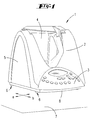
- FIG. 1 Shown and described is first with reference to Fig. 1 a food processor 1 with a mixing vessel receptacle 2 and a control panel 3.
- the food processor 1 is associated with a stirring bowl 4. This sits in the mixing vessel receptacle 2 a.
- the stirring bowl 4 is associated with a Stirring, provided an agitator, which is operated via a arranged in the kitchen machine 1 below the receptacle 2, not shown electric drive.
- the housing 5 of the food processor 1 is supported by support feet 6 on a surface, here on a table surface 7.
- the support feet 6 are for this purpose attached to the underside of a housing bottom 8.
- the food processor 1 is suitable, inter alia, for the production of doughs.
- a high resistance is opposed to the rotating agitator by the dough's toughness.
- the required drive torque of the motor is supported by the housing 5 and the support feet 6. If the dough ball is arranged unfavorably in the mixing vessel 4, the agitator may remain stuck in the dough for a short time. As a result, the torque is briefly increased. This momentum shock is compensated by the support legs 6, so that the device does not jerky and jump around its center of gravity.
- the movement of the housing 5 in the horizontal direction is allowed.
- the housing 5 can move relative to the support legs 6 or, as explained in more detail below, relative to a section of the support feet 6 in the horizontal plane.
- the abruptly introduced energy is converted into friction and / or restoring and deformation energy.
- the support legs 6 are in this case further connected to the base - here the table surface 7 - connected, in particular frictionally connected.
- the Fig. 2 to 4 show a first embodiment of a support foot 6.
- This is basically designed in two parts, with a part is provided fixed to the housing.
- This is an extension 9, the housing side, in particular is formed on the housing bottom side and protrudes vertically downwards over the downwardly directed housing bottom surface.
- the projection 9 is designed as a rigid part, more preferably according to one-piece, uniform material configuration together with the housing bottom 8. Accordingly, it may be in the extension 9 to a hard plastic or metal body, which further preferably with respect to a central extension 9 passing through the vertical axis x is rotationally symmetrical.
- an extension 9 is alternatively provided, which can be fixed on the underside of the housing base 8, for example screwed.
- the extension 9 forms a shell part 10 which opens vertically downwards and whose outer diameter corresponds to the outer diameter of the extension 9.
- the circumferential shell wall 11 limits in the horizontal direction a shell space 12, wherein the wall thickness in the illustrated embodiment corresponds to about 1/20 of the shell part outer diameter.
- the vertical height of the shell wall 11 preferably corresponds to about 1/4 of the shell part outer diameter.
- the resulting tray bottom 13 extends in a direction transverse to the vertical axis x plane, further in a horizontal plane, which is aligned parallel to the table surface. 7
- a mandrel part 14 is provided in the shell part 10, further engaging in the shell space 12, a mandrel part 14 is provided. Again, this is preferably a rotationally symmetrical component with a vertically upwardly facing end face 15, which is aligned parallel to the tray bottom 13, according to also preferably extends in a horizontal plane.
- the mandrel part 14 is part of an elastomer part 16.
- the latter has a bottom 17, with a vertically downwardly facing base surface 18 for support on the table surface 7.
- the bottom 17 is formed in the illustrated embodiment in plan view circular disk as a diameter, which corresponds approximately to 2 times the outer diameter of the mandrel part 14.
- the latter sits centrally on the floor 17 and is connected to this, more preferably of the same material and integrally connected thereto.
- the vertical height of the mandrel part 14 is selected so that the shell part 10 in assignment position, d. H. in the resting position of the shell bottom 13 on the end face 15 of the mandrel part 14 free-cutting ends, d. H. with a vertical distance to the facing surface of the elastomerteil stoolen bottom 17 ends.
- a vertical height of the mandrel member 14 is selected, which corresponds approximately to 2 times the vertical depth of the shell part 10 and the vertical height of the shell wall 11.
- the mandrel part 13 is received in the shell part 10 with a play remaining transverse to the Dorner extension, so that a relative mobility of the shell part 10 or of the extension 9 to the mandrel part 14 can be achieved.
- the remaining game (addition of both sides of the mandrel part 14 in Fig. 3 adjusting game dimensions c) summarized about 1/6 of the free inner diameter d of the shell part 10th
- the latter is connected to the bottom 17 of the elastomeric part 16 along the peripheral edge and extends like a sheath under conical taper with increasing vertical spacing to the bottom 17 to the transition region of the shell part 10 and extension 9.
- the shell section 19 rastgehaltert to the extension 9, for which purpose a corresponding circumferential compression 20 of the shell portion 19 engages in an outer wall of the extension 9 provided annular groove 21.
- the jacket portion 19 is formed in particular thinner compared to the bottom 17, further membrane-like with a material thickness of 0.1 to 0.5 mm. This results in a high flexibility of the shell section 19.
- the latter is set resiliently resilient due to the preferably uniform elastomeric properties.
- a support leg 6 is a floating support in the horizontal direction of movement a and b given in the vertical direction of movement
- the connection between extension and elastomeric member 16 is stiff, so that subcritical vibrations, caused for example by an unbalance excitation, can be well compensated ,
- a sliding of the extension 9 relative to the mandrel part 14 in the region of the superposed surfaces (shell bottom 13 and end face 15) can be reached (see. Fig. 4 ), wherein the horizontal movement is limited by the overlapping shell wall 11.
- the frictional resistance between the shell bottom and end face 15 of the mandrel part 14 is less than the frictional resistance between the base surface 18 of the elastomer part 16 and the table surface. 7
- the skirt portion 19 formed as a thin elastic layer in this case does not affect the movement of the housing 5 or of the permanently attached thereto Fortsatzes 9, but only serves to fix when lifting and carrying the device and to cover the created cavity. By removing the latching connection, the elastomeric member 16 can be easily removed and thus cleaned separately.
- elastomer part 16 preference is given to using natural rubbers or synthetic rubbers, for example styrene-butadiene rubber.
- the housing-side projection 9 forms a vertically downward facing, rigid mandrel part 14, which dips into a vertically upwardly open shell part 10.
- the shell part 10 is formed here as an elastomeric member 16, with a resting with its base 18 in the use position on the table surface 7 shell bottom 13 and a bottom side, edge preferably peripheral shell wall 11 whose vertical height is dimensioned smaller than that of the mandrel part 14. The latter supports with the vertically downwardly facing end face on the facing surface of the shell bottom 13 from.
- the shell part 10 has in the illustrated embodiment an inner diameter which corresponds approximately to 3 times the mandrel part diameter. Consequently, the mandrel part 14 is also accommodated here with a horizontal play in the shell part 10, so that a relative displacement is allowed according to shocks or vibrations in the food processor 1. Also here is the frictional resistance between the mandrel part end face 15 and the shell bottom 13 is selected to be smaller than between the standing surface 18 of the shell bottom 13 and the table surface 7, so that the shell-like elastomer part 16 remains connected to the table surface 7 even with the introduction of energy jump.
- the shell space 12 is covered by a penetrated by the mandrel part 14 shell cover 22.
- This shell ceiling 22 is circumferentially secured in the region of the free upwardly projecting vertically upright edge on the shell wall 11 and has in a basic orientation centrally a passage opening for the mandrel part 14. Along the edge of the passage opening, the membrane-like shell ceiling 22 is connected, for example, by gluing or welding to the mandrel part 14 (cf. Fig. 6 ).
- the shell space 12 is closed.
- this can be achieved by stretching or compressing the horizontal movement of the mandrel part 14 relative to the shell part 10 (cf. Fig. 7 ).
- FIG. 8 to 10 Another embodiment show the Fig. 8 to 10 , Also in this embodiment, the housing 5 of the food processor 1 on a projecting vertically down projection 9. This is designed as a rigid part, in particular as hard plastic or metal part, this further cone-like rotationally symmetrical.
- the extension 9 has an external thread 23. On this a nut 24 is turned on, over which the extension 9 with the interposition of Disk parts 25 supported on a standing surface 18 forming stand part 26.
- the latter is initially dish-shaped with a diameter corresponding to a multiple, in the illustrated embodiment, about a 4 times the extension diameter.
- the central area of the standing part 26 is raised in relation to the standing area 18, so that the standing area 18 results peripherally around the edge of the standing part 26.
- the central raised region of the standing part 26 forms a support surface 27 extending in a horizontal plane.
- the disk parts 25 are further preferably of the same design, this at first in particular with regard to their thickness considered in the vertical direction and also with regard to their inner and outer diameters. Furthermore, the disk parts 25 are preferably also identical in terms of the choice of material, with the disk parts 25 furthermore being made of a hard plastic or of a metal material.
- the disk parts 25 are in the region of their passage openings 29 interspersed by an elastomeric part 30.
- This is an overall cord-like elastomer part, which is anchored on both sides end, namely on the one in the direction of the passage openings 29 facing end side of the extension 9 and the For anchoring in the illustrated embodiment, the respective receptacle 31 is undercut for the Elastomerer toode. Accordingly, the elastomeric member 30 is set so that it can not solve under the usual tensile stress from the respective anchorage.
- the stacked disc parts 25 are flat with their friction surfaces on top of each other, these being stacked horizontally flexible due to the central enforcement of the elastomeric member 39.
- the formed as an elastic band or elastic cord elastomer member 30 connects the friction surfaces to a loosely bound component, the flexibility and thus the horizontal limitation and mobility is adjustable in particular by the length, the diameter and the choice of material of the disc parts 25.
- Fig. 9 is an ideal basic position of the support leg 6 shown. According to above-described loads in the horizontal direction (arrows a + b) results in a possibly uneven displacement of the disk parts 25 according to Fig. 10 , according to which the tension of the extension 9 against the base part 26, the elastomeric member 30 is claimed to train.
- the elastomer part 30 is further preferably designed such that a return to the basic position according to FIG Fig. 9 can be achieved.
- a new, random orientation of the disc parts 25 to each other and an alignment of the extension 9 is achieved to the disc parts 25 during operation of the food processor 1 again and again.
- the nut 24 serves primarily to prevent the loss of one of the functional elements. In addition, a bias of the functional elements can be achieved via the nut 24 so as to vary the friction properties.
- the external thread 23 which carries the screw nut 24 is preferably also used for fixing the extension 9 on the housing 5, in particular on the housing bottom 8.
- the support leg 6 is in one piece, preferably of the same material formed as an elastomeric member 32.
- This is composed of a vertically upwardly open shell part 33, the shell bottom 34 forms the base 35 on the underside. Again, this is preferably a rotationally symmetric part.
- the corresponding encircling, shell bottom edge side arranged and extending vertically upwardly shell wall has a vertical height which corresponds approximately to the outer radius of the shell bottom 34.
- Radially outside the shell wall 36 goes over in a, designed for resting on the table surface 7 support wall 37. This starts at the freely projecting vertically upward end of the shell wall 36 and extends in a cross-section circular segment-shaped up to the level of the base 35, so that a total of a dome-shaped shape of the shell part 33 sets.
- the vertically upwardly facing free edge of the shell wall 36 defines an exit plane. Through this enters a tubular connecting portion 38.
- the connecting portion 38 has an outer diameter e, in the illustrated embodiment about 0.8 times the smallest free inner diameter of the shell part 33 corresponds. This results in a corresponding distance f between the outer wall of the connecting portion 38 and the inner surface of the shell wall, which is preferably 1 to 5 mm.
- the tube-like connecting portion 38 extends over a length which is approximately twice the vertical height of the shell wall 36 and forms a connection region 39 in the end section protruding beyond the shell part 33. This is formed by a radial thickening by means of which the support foot 6 thus formed on the housing bottom 8 can be fixed.
- the impact energy is converted into restoring and deformation energy, wherein the elastomeric member 32 acts in the manner of an elastomeric spring. Due to the geometric design, a high rigidity in the vertical direction according to the cylindrically configured connecting portion 38 is realized with simultaneous high elasticity in the horizontal direction according to the connection of the connecting portion 38 to the shell part 33.
- the connecting section 38 automatically turns into the basic position after the forces acting on it cease to exist Fig. 12 back.
Landscapes
- Engineering & Computer Science (AREA)
- Mechanical Engineering (AREA)
- General Engineering & Computer Science (AREA)
- Food Science & Technology (AREA)
- Health & Medical Sciences (AREA)
- Child & Adolescent Psychology (AREA)
- Food-Manufacturing Devices (AREA)
- Table Equipment (AREA)
- Vibration Prevention Devices (AREA)
- Legs For Furniture In General (AREA)
Description
- Die Erfindung betrifft einen Standfuß nach den Merkmalen des Oberbegriffes des Anspruchs 1.
- Standfüße insbesondere für Küchenmaschinen sind bekannt. Diese sind zur Abstützung der Küchenmaschine auf einer Fläche, insbesondere auf einer Tischfläche ausgelegt, wobei weiter bevorzugt über den Standfuß in der Küchenmaschine hervorgerufene Sprünge und Schwingungen reduziert werden. Hierbei besteht das Elastomerteil bevorzugt aus einem Gummimaterial oder aus einem thermoplastischen Elastomer.
- Aus der
DE 88 11 934 U1 ist für ein Motorlager für Kleinmotoren ein Standfuß bekannt, bei dem das Elastomerteil unterseitig in eine schalenartige Form übergeht, die außenseitig formschlüssig eine Gehäuse-Leiterplatte umgreift. Eine Auslenkung des Verbindungsabschnittes ist nur im begrenzten Ausmaß möglich. Bei einer ein Ringteil aufweisenden Ausführungsform, über welches der Standfuß sich auf einer Fläche abstützt, ist ein Verbindungsabschnitt über radiale Stege an dem Kreisteil abgestützt, so dass der Verbindungsabschnitt sich über diese Stege und das Kreisteil auf dem Boden abstützt. - Aus der
WO90/07658 A - Aus der
US 2005/0115022 A1 ist ein hülsenartiges Teil bekannt, das auf einen Möbelfuß von unten aufgeschoben wird, wobei der Möbelfuß in das Innere des Schalenteils eingreift. - Ausgehend von dem zunächst genannten Stand der Technik beschäftigt sich die Erfindung mit der Aufgabe, einen Standfuß anzugeben, der insbesondere im Hinblick auf eine Küchenmaschine geeignet ist.
- Diese Aufgabe ist beim Gegenstand des Anspruches 1 gelöst, wobei darauf abgestellt ist, dass ein Schalenboden, der umgeben von der Schalenwandung in Verbindungsabschnitt trägt, sich im Betriebszustand auf einer Tischfläche oder dergleichen abstützt und dass die Schalenöffnung nach vertikal oben weist.
- Anbindungsbereich und Verbindungsabschnitt des Elastomerteils sind hierbei in bevorzugter Ausgestaltung einstückig, weiter bevorzugt materialeinheitlich ausgebildet, weiter bevorzugt entsprechend elastomere Eigenschaften aufweisend. Das Elastomerteil weist das die Standfläche ausbildende Schalenteil auf. Der Schalenboden trägt umgeben von der Schalenwandung den Verbindungsabschnitt, wobei auch hier bevorzugt eine einstückige, weiter bevorzugt materialeinheitliche Verbindung von Verbindungsabschnitt und Schalenteil gewählt ist. Zufolge dieser Ausgestaltung ist eine Stoßenergie, beispielsweise resultierend aus einem Rührbetrieb der Küchenmaschine, in Rückstell- und Verformungsenergie des Elastomerteils umwandelbar. Durch die beschriebene geometrische Gestaltung ist eine hohe Steifigkeit in vertikaler Richtung bei gleichzeitiger hoher Elastizität in horizontaler Richtung realisiert. Stöße bzw. Schwingungen in Horizontalrichtung werden zufolge elastischer Auslenkung des an dem Schalenteil wurzelnden Verbindungsabschnittes aufgefangen, derart, dass sich keine Relativverlagerung des so gebildeten Standfußes gegenüber der Aufstellfläche (Tischfläche) einstellt. Die Verschwenkbarkeit des Verbindungsabschnittes ist begrenzt durch die umlaufende Schalenwandung, welche in einer maximalen Auslenkstellung des Verbindungsabschnittes eine zusätzliche Abstützung desselben erbringt und somit entsprechend das Maß einer maximalen Auslenkung definiert.
- Der Verbindungsabschnitt ist in einer bevorzugten Ausgestaltung als Massivkörper gebildet. Günstigere Eigenschaften zur Umwandlung von Stoßenergie in Verformungsenergie sind erreicht bei Ausbildungen des Verbindungsabschnittes als Hohlkörper, weiter bevorzugt durch rohrartige Ausgestaltung desselben, wobei bevorzugt die Rohrachse vertikal verläuft, weiter bevorzugt senkrecht zu einer Standfläche. Die Verbindung des Verbindungsabschnittes mit dem Schalenteil, insbesondere mit dem Schalenboden ist erreicht im Bereich eines Rohrendes. Die Rohrwandung wurzelt entsprechend in dem Schalenboden, geht weiter bevorzugt materialeinheitlich und einteilig in diesen über. Dieser Übergang ist in bevorzugter Ausgestaltung im Querschnitt scharfkantig, kann jedoch in weiterer Ausgestaltung auch mit Radien ausgeführt sein, was die Elastizität beeinflusst. Auch können die Funktionseigenschaften durch eine weiche Anbindung des Verbindungsabschnittes an den Schalenboden optimiert werden.
- Das freie Abstandsmaß zwischen einer Außenfläche des Verbindungsabschnittes und einer Innenfläche des umlaufenden Schalenteiles entspricht in weiter bevorzugter Ausgestaltung 1/10 bis 1/5 des Durchmessers des Verbindungsabschnittes, dies weiter mit Bezug auf den Bereich des Verbindungsabschnittes, der bei einer entsprechenden Auslenkung zuerst die umlaufende Schalenwandung kontaktiert.
- In bevorzugter Ausgestaltung erstreckt sich die Schalenwandung nur über einen Teil der Höhe des Verbindungsabschnittes, so weiter bevorzugt nur über 1/4 bis 2/3 der Höhe des Verbindungsabschnittes, so dass Letzter mit dem dem Wurzelbereich abgewandten Ende frei über das Schalenteil, insbesondere über die Schalenwandung nach vertikal oben hinaus abragt, was eine günstige Anbindung an das Gerätegehäuse bietet. Die Anbindung ist hierbei weiter so gewählt (dies weiter auch in Abhängigkeit mit der vorbeschriebenen Vorstandslänge des Verbindungsabschnittes), dass eine Bodenunterseite des Gehäuses insbesondere im Anbindungsbereich vertikal beabstandet ist zu dem Schalenteil, weiter zu der nach vertikal oben weisenden Randkante der Schalenwandung.
- Weiter bevorzugt geht die Schalenwandung radial außen in eine, zur Auflage auf den Boden bzw. auf der Aufstandsfläche ausgelegte Stützwandung über. Diese ist bevorzugt einstückig, weiter bevorzugt materialeinheitlich mit dem Schalenteil verbunden und bietet eine Abstützung des gesamten Elastomerteiles zur Sicherung desselben gegen Kippen.
- Alle Zwischenwerte, insbesondere in 1 mm-Schritten und hinsichtlich einer ein-oder mehrfachen Einengung der angegebenen Bereichsgrenze in derselben Schrittweise, von oben und/oder von unten, sind hiermit in die Offenbarung eingeschlossen.
- Nachstehend ist die Erfindung anhand der beigefügten Zeichnung, welche lediglich vier Ausführungsbeispiele darstellt, näher erläutert. Es zeigt:
- Fig. 1
- in perspektivischer Darstellung eine Tisch-Küchenmaschine mit Standfüßen zum Aufstellen der Küchenmaschine auf einer Tischfläche;
- Fig. 2
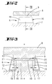
- einen gerätebodenseitig angeordneten Standfuß in einer nicht erfindungsgemässen Ausführungsform;
- Fig. 3
- den Schnitt gemäß der Linie III-III in
Fig. 2 , eine unbelastete Grundstellung betreffend; - Fig. 4
- eine der
Fig. 3 entsprechende Darstellung, jedoch in einer Belastungsstellung; - Fig. 5
- eine der
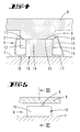
Fig. 2 entsprechende Darstellung, jedoch eine zweite nicht erfindungsgemässe Ausführungsform betreffend; - Fig. 6
- den Schnitt gemäß der Linie VI-VI in
Fig. 5 ; - Fig. 7
- eine Schnittdarstellung gemäß
Fig. 6 , eine belastete Stellung betreffend; - Fig. 8
- eine weitere der
Fig. 2 entsprechende Darstellung, eine dritte nicht erfindungsgemässe Ausführungsform betreffend; - Fig. 9
- den Schnitt gemäß der Linie IX-IX in
Fig. 8 ; - Fig. 10
- eine der
Fig. 9 entsprechende Darstellung, eine Belastungsstellung betreffend; - Fig. 11
- eine der
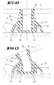
Fig. 2 entsprechende Darstellung, eine erfindungsgemässe Ausführungsform betreffend; - Fig. 12
- den Schnitt gemäß der Linie XII-XII in
Fig. 11 ; - Fig. 13
- eine der
Fig. 12 entsprechende Darstellung, jedoch im Zuge einer Belastung. - Die
Figuren 2 bis 10 stellen keine Ausführungsformen der Erfindung dar. - Dargestellt und beschrieben ist zunächst mit Bezug zu
Fig. 1 eine Küchenmaschine 1 mit einer Rührgefäß-Aufnahme 2 und einem Bedienfeld 3. - Der Küchenmaschine 1 ist ein Rührtopf 4 zugeordnet. Dieser sitzt in der Rührgefäß-Aufnahme 2 ein. In dem Rührtopf 4 ist zugeordnet einem Rührtopfboden, ein Rührwerk vorgesehen, welches über einen in der Küchenmaschine 1 unterhalb der Aufnahme 2 angeordneten, nicht dargestellten Elektroantrieb betrieben wird.
- Das Gehäuse 5 der Küchenmaschine 1 stützt sich über Stützfüße 6 auf einer Fläche, hier auf einer Tischfläche 7 ab. Die Stützfüße 6 sind hierzu unterseitig eines Gehäusebodens 8 befestigt.
- Die Küchenmaschine 1 ist unter anderem geeignet zur Herstellung von Teigen. In einem solchen Teigmodus wird mit dem sich drehenden Rührwerk durch die Zähigkeit des Teiges ein hoher Widerstand entgegengesetzt. Das erforderliche Antriebsmoment des Motors wird über das Gehäuse 5 und die Stützfüße 6 abgestützt. Ist die Teigkugel ungünstig im Rührgefäß 4 angeordnet, bleibt das Rührwerk gegebenenfalls kurzzeitig im Teig stecken. Zufolge dessen wird das Drehmoment kurzzeitig erhöht. Dieser Momentenstoß wird von den Stützfüßen 6 kompensiert, so dass sich das Gerät nicht ruckartig und sprunghaft um seinen Schwerpunkt dreht.
- Die Bewegung des Gehäuses 5 in horizontaler Richtung (vgl. Pfeile a und b in
Fig. 1 ) wird zugelassen. Das Gehäuse 5 kann sich relativ zu den Stützfüßen 6 bzw., wie nachstehend näher erläutert, relativ zu einem Teilabschnitt der Stützfüße 6 in der horizontalen Ebene bewegen. Die sprungartig eingeleitete Energie wird in Reibung und/oder Rückstell- und Verformungsenergie umgewandelt. Die Stützfüße 6 sind hierbei weiter mit der Standfläche - hier der Tischfläche 7 - verbunden, insbesondere reibschlüssig verbunden. - Die
Fig. 2 bis 4 zeigen eine erste Ausführungsform eines Stützfußes 6. Dieser ist grundsätzlich zweiteilig gestaltet, wobei ein Teil gehäusefest vorgesehen ist. Hierbei handelt es sich um einen Fortsatz 9, der gehäuseseitig, insbesondere gehäusebodenseitig angeformt ist und nach vertikal unten über die nach unten gerichtete Gehäusebodenfläche abragt. Der Fortsatz 9 ist als Starrteil ausgebildet, weiter bevorzugt zufolge einstückiger, materialeinheitlicher Ausgestaltung zusammen mit dem Gehäuseboden 8. Entsprechend kann es sich bei dem Fortsatz 9 um einen Hartkunststoff- oder Metallkörper handeln, der weiter bevorzugt mit Bezug auf eine zentrale den Fortsatz 9 durchsetzende Vertikalachse x rotationssymmetrisch ausgebildet ist. Neben der einstückigen Ausgestaltung ist alternativ ein Fortsatz 9 vorgesehen, der unterseitig am Gehäuseboden 8 festlegbar, beispielsweise einschraubbar ist. - Der Fortsatz 9 formt ein sich nach vertikal unten öffnendes Schalenteil 10 aus, dessen Außendurchmesser dem Außendurchmesser des Fortsatzes 9 entspricht. Die umlaufende Schalenwandung 11 begrenzt in Horizontalrichtung einen Schalenraum 12, wobei die Wandungsstärke in dem dargestellten Ausführungsbeispiel etwa 1/20 des Schalenteil-Außendurchmessers entspricht. Die vertikale Höhe der Schalenwandung 11 entspricht bevorzugt etwa 1/4 des Schalenteil-Außendurchmessers.
- Der sich hieraus ergebende Schalenboden 13 erstreckt sich in einer quer zur Vertikalachse x gerichteten Ebene, weiter in einer Horizontalebene, die entsprechend parallel ausgerichtet ist zur Tischfläche 7.
- In das Schalenteil 10, weiter in den Schalenraum 12 eingreifend ist ein Dornteil 14 vorgesehen. Auch hierbei handelt es sich bevorzugt um ein rotationssymmetrisches Bauteil mit einer vertikal nach oben weisenden Stirnfläche 15, die parallel ausgerichtet ist zum Schalenboden 13, entsprechend sich auch bevorzugt in einer Horizontalebene erstreckt.
- Das Dornteil 14 ist Teil eines Elastomerteils 16. Letzteres weist einen Boden 17 auf, mit einer vertikal nach unten weisenden Standfläche 18 zur Abstützung auf der Tischfläche 7. Der Boden 17 ist in dem dargestellten Ausführungsbeispiel im Grundriss kreisrund als Scheibe ausgebildet, mit einem Durchmesser, der etwa dem 2-Fachen des Außendurchmessers des Dornteils 14 entspricht. Letzteres sitzt zentral auf dem Boden 17 und ist mit diesem verbunden, weiter bevorzugt materialeinheitlich und einstückig mit diesem verbunden.
- Die vertikale Höhe des Dornteiles 14 ist so gewählt, dass das Schalenteil 10 in Zuordnungsstellung, d. h. in der Auflagestellung des Schalenbodens 13 auf der Stirnfläche 15 des Dornteils 14 freikragend endet, d. h. mit vertikalem Abstand zur zugewandten Oberfläche des elastomerteilseitigen Bodens 17 endet. So ist in dem dargestellten Ausführungsbeispiel eine vertikale Höhe des Dornteiles 14 gewählt, die etwa dem 2-Fachen der vertikalen Tiefe des Schalenteiles 10 bzw. der vertikalen Höhe der Schalenwandung 11 entspricht.
- Das Dornteil 13 ist in dem Schalenteil 10 mit einem quer zu der Dornerstreckung verbleibenden Spiel aufgenommen, so dass eine relative Beweglichkeit des Schalenteils 10 bzw. des Fortsatzes 9 zu dem Dornteil 14 erreichbar ist. So entspricht in dem dargestellten Ausführungsbeispiel das verbleibende Spiel (Addition der sich beidseitig des Dornteiles 14 in
Fig. 3 einstellenden Spielmaße c) zusammengefasst etwa 1/6 des freien Innendurchmessers d des Schalenteiles 10. - Außenseitig ist das Schalenteil 10 umfasst von einem Mantelabschnitt 19 des Elastomerteils 16. Letzterer ist an dem Boden 17 des Elastomerteils 16 entlang der Randkante angebunden und erstreckt sich hüllenartig unter konischer Verjüngung bei zunehmender vertikaler Beabstandung zum Boden 17 bis in den Übergangsbereich von Schalenteil 10 und Fortsatz 9. Hier ist der Mantelabschnitt 19 an dem Fortsatz 9 rastgehaltert, wozu eine entsprechende umlaufende Verdichtung 20 des Mantelabschnittes 19 in eine wandungsaußenseitig des Fortsatzes 9 vorgesehene Ringnut 21 eingreift.
- Der Mantelabschnitt 19 ist insbesondere gegenüber dem Boden 17 verdünnt ausgebildet, weiter membranartig mit einer Materialstärke von 0,1 bis 0,5 mm. Hieraus ergibt sich eine hohe Flexibilität des Mantelabschnittes 19. Letzterer ist zufolge der bevorzugt einheitlichen Elastomereigenschaften elastisch rückstellfähig eingestellt. Mittels des Mantelabschnittes 19 ist der Zusammenwirkungsbereich von Dornteil 14 und Schalenteil 10 beispielsweise vor Verschmutzungen geschützt. Zudem ist hierdurch eine unverlierbare Anbindung des Dornteiles 14 an den Fortsatz 9 gegeben.
- Zufolge der vorbeschriebenen Ausgestaltung eines Stützfußes 6 ist eine schwimmende Lagerung in der horizontalen Bewegungsrichtung a und b gegeben, wobei in vertikaler Bewegungsrichtung die Verbindung zwischen Fortsatz und Elastomerteil 16 steif gestaltet ist, so dass unterkritische Schwingungen, beispielsweise hervorgerufen durch eine Unwuchterregung, gut kompensiert werden können. Hierbei ist ein Abgleiten des Fortsatzes 9 relativ zu dem Dornteil 14 im Bereich der aufeinanderliegenden Flächen (Schalenboden 13 und Stirnfläche 15) erreichbar (vgl.
Fig. 4 ), wobei die Horizontalbewegung zufolge der überlappenden Schalenwandung 11 begrenzt ist. - Hierbei ist der Reibungswiderstand zwischen Schalenboden und Stirnfläche 15 des Dornteiles 14 geringer als der Reibungswiderstand zwischen der Standfläche 18 des Elastomerteils 16 und der Tischfläche 7.
- Der als dünne elastische Schicht ausgebildete Mantelabschnitt 19 beeinträchtigt hierbei nicht die Bewegung des Gehäuses 5 bzw. des an diesem fest angebrachten Fortsatzes 9, sondern dient lediglich zur Fixierung beim Hochheben und Tragen des Gerätes sowie zur Abdeckung des geschaffenen Hohlraums. Durch Aufhebung der Rastverbindung kann das Elastomerteil 16 leicht abgenommen werden und so separat gereinigt werden.
- Zur Bildung des Elastomerteils 16 kommen bevorzugt Naturkautschuke oder synthetische Kautschuke wie beispielsweise Styrol-Butadien-Kautschuk zur Anwendung.
- Die
Fig. 5 bis 7 zeigen eine zweite Ausführungsform. Hier formt der gehäuseseitige Fortsatz 9 ein nach vertikal unten weisendes, starres Dornteil 14 aus, das in ein nach vertikal oben offenes Schalenteil 10 eintaucht. Das Schalenteil 10 ist hier als Elastomerteil 16 gebildet, mit einem mit seiner Standfläche 18 in der Nutzungsstellung auf der Tischfläche 7 aufliegenden Schalenboden 13 und einer bodenseitig, randseitig bevorzugt umlaufenden Schalenwandung 11, deren vertikale Höhe geringer bemessen ist als die des Dornteils 14. Letzteres stützt sich mit der vertikal nach unten weisenden Stirnfläche auf der zugewandten Oberfläche des Schalenbodens 13 ab. - Die Zusammenwirkung von dornteilseitiger Stirnfläche 15 und zugewandter Oberfläche des Schalenbodens 13 ist auch in diesem Ausführungsbeispiel in einer ebenen Fläche erreicht, weiter bevorzugt in einer Horizontalebene.
- Das Schalenteil 10 weist in dem dargestellten Ausführungsbeispiel einen Innendurchmesser auf, der etwa dem 3-Fachen des Dornteildurchmessers entspricht. Demzufolge ist das Dornteil 14 auch hier mit einem horizontalen Spiel in dem Schalenteil 10 aufgenommen, so dass eine Relativverlagerung zufolge Stöße oder Schwingungen in der Küchenmaschine 1 erlaubt sind. Auch ist hierbei der Reibungswiderstand zwischen der dornteilseitigen Stirnfläche 15 und dem Schalenboden 13 geringer gewählt als zwischen der Standfläche 18 des Schalenbodens 13 und der Tischfläche 7, so dass das schalenartige Elastomerteil 16 auch bei Einleitung sprungartiger Energie mit der Tischfläche 7 verbunden bleibt.
- Der Schalenraum 12 ist überdeckt von einer vom Dornteil 14 durchsetzten Schalendecke 22. Diese ist, wie der Mantelabschnitt 19 der ersten Ausführungsform, gegenüber der Schalenwandung 11 hinsichtlich der Materialstärke verringert, zur Bildung der Schalendecke 22 in Art einer elastischen Membran. Diese Schalendecke 22 ist umlaufend im Bereich des freien nach vertikal oben ragenden Randes an der Schalenwandung 11 befestigt und weist in einer Grundausrichtung zentral eine Durchtrittsöffnung für das Dornteil 14 auf. Entlang des Randes der Durchtrittsöffnung ist die membranartige Schalendecke 22 beispielsweise durch Verkleben oder Verschweißen mit dem Dornteil 14 verbunden (vgl.
Fig. 6 ). - Zufolge dieser Anordnung ist der Schalenraum 12 verschlossen. Durch die rückstellfähig elastische Ausgestaltung der Schalendecke 22 kann diese zufolge Dehnung bzw. Stauchung die Horizontalbewegung des Dornteiles 14 relativ zum Schalenteil 10 mit vollziehen (vgl.
Fig. 7 ). - Eine weitere Ausführungsform zeigen die
Fig. 8 bis 10 . Auch in dieser Ausführungsform weist das Gehäuse 5 der Küchenmaschine 1 einen nach vertikal unten abragenden Fortsatz 9 auf. Dieser ist als Starrteil, insbesondere als Hartkunststoff- oder Metallteil ausgebildet, dies weiter zapfenartig rotationssymmetrisch. - Der Fortsatz 9 weist ein Außengewinde 23 auf. Auf dieses ist eine Schraubmutter 24 aufgedreht, über welche sich der Fortsatz 9 unter Zwischenschaltung von Scheibenteilen 25 auf einem die Standfläche 18 ausbildenden Standteil 26 abstützt. Letzteres ist zunächst tellerartig gestaltet mit einem Durchmesser, der einem Mehrfachen, in dem dargestellten Ausführungsbeispiel etwa einem 4-Fachen des Fortsatz-Durchmessers entspricht. Der mittige Bereich des Standteiles 26 ist gegenüber der Standfläche 18 erhaben, so dass sich die Standfläche 18 umlaufend randseitig des Standteiles 26 ergibt.
- Der mittige erhabene Bereich des Standteiles 26 formt eine sich in einer Horizontalebene erstreckende Stützfläche 27.
- Zwischen der fortsatzseitigen Schraubmutter 24 und der standteilseitigen Stützfläche 27 sind in dem dargestellten Ausführungsbeispiel neun flächig aufeinanderliegende Scheibenteile 25 gespannt. Diese Scheibenteile 25 sind als Ringteile 28 ausgebildet, weisen entsprechend jeweils eine zentrale Durchtrittsöffnung 29 auf. Hierbei ist der Durchmesser der Durchtrittsöffnung 29 angepasst an den Außendurchmesser des Fortsatzes 9, weiter bevorzugt diesen Außendurchmesser geringfügig übertreffend, so dass ein nach vertikal unten weisendes Ende des Fortsatzes 9 je nach Drehverlagerung der Schraubmutter 24 mehr oder weniger in eine oder mehrere Durchtrittsöffnungen 29 der Scheibenteile 25 eintaucht.
- Die Scheibenteile 25 sind weiter bevorzugt gleichgestaltet, dies zunächst insbesondere hinsichtlich ihrer in Vertikalrichtung betrachteten Dicke als auch hinsichtlich ihrer Innen- und Außendurchmesser. Weiter sind die Scheibenteile 25 bevorzugt auch hinsichtlich der Materialwahl gleichgestaltet, wobei weiter die Scheibenteile 25 aus einem Hartkunststoff oder auch aus einem Metallwerkstoff bestehen.
- Die Scheibenteile 25 sind im Bereich ihrer Durchtrittsöffnungen 29 durchsetzt von einem Elastomerteil 30. Hierbei handelt es sich um ein insgesamt schnurartiges Elastomerteil, das beidseitig endseitig verankert ist, nämlich zum einen im Bereich der in Richtung auf die Durchtrittsöffnungen 29 weisenden Stirnseite des Fortsatzes 9 und zum anderen in dem Mittenabschnitt des Standteiles 26. Zur Verankerung ist in dem dargestellten Ausführungsbeispiel die jeweilige Aufnahme 31 für das Elastomerteilende hinterschnitten. Entsprechend ist das Elastomerteil 30 so festgelegt, dass sich dieses auch unter üblicher Zugbeanspruchung nicht aus der jeweiligen Verankerung lösen kann.
- Die übereinandergestapelten Scheibenteile 25 liegen plan mit ihren Reibflächen aufeinander, wobei diese zufolge der mittigen Durchsetzung mit dem Elastomerteil 39 horizontal flexibel übereinandergestapelt sind. Das als elastisches Band oder als elastische Schnur gebildete Elastomerteil 30 verbindet die Reibflächen zu einer lose gebundenen Komponente, wobei die Flexibilität und damit die horizontale Begrenzung und Beweglichkeit insbesondere durch die Länge, den Durchmesser und die Materialwahl der Scheibenteile 25 einstellbar ist.
- In
Fig. 9 ist eine ideale Grundstellung des Stützfußes 6 dargestellt. Zufolge vorbeschriebener Belastungen in Horizontalrichtung (Pfeile a + b) ergibt sich eine unter Umständen ungleichmäßige Verlagerung der Scheibenteile 25 gemäßFig. 10 , wobei zufolge der Verspannung des Fortsatzes 9 gegen das Standteil 26 das Elastomerteil 30 auf Zug beansprucht wird. Das Elastomerteil 30 ist hierbei weiter bevorzugt so ausgelegt, dass über dieses eine Rückstellung in die Grundstellung gemäßFig. 9 erreicht werden kann. Weiter wird jedoch im laufenden Betrieb der Küchenmaschine 1 immer wieder eine neue, zufällige Ausrichtung der Scheibenteile 25 zueinander sowie eine Ausrichtung des Fortsatzes 9 zu den Scheibenteilen 25 erreicht. - Die Schraubmutter 24 dient in erster Linie zur Verhinderung des Verlierens eines der Funktionselemente. Darüber hinaus ist über die Schraubmutter 24 eine Vorspannung der Funktionselemente erreichbar, um so die Reibungseigenschaften zu variieren. Das die Schraubmutter 24 tragende Außengewinde 23 dient bevorzugt weiter auch zur Festlegung des Fortsatzes 9 am Gehäuse 5, insbesondere am Gehäuseboden 8.
- Eine erfindungsgemässe Ausführungsform zeigen die
Fig. 11 bis 13 . Hier ist der Stützfuß 6 einteilig, bevorzugt materialeinheitlich als Elastomerteil 32 gebildet. Dieses setzt sich zusammen aus einem nach vertikal oben offenen Schalenteil 33, dessen Schalenboden 34 unterseitig die Standfläche 35 bildet. Auch hierbei handelt es sich bevorzugt um ein rotationssymmetrisches Teil. Die entsprechend umlaufende, schalenbodenrandseitig angeordnete und sich nach vertikal oben erstreckende Schalenwandung weist eine vertikale Höhe auf, die etwa dem Außenradius des Schalenbodens 34 entspricht. - Radial außen geht die Schalenwandung 36 in eine, zur Auflage auf die Tischfläche 7 ausgelegte Stützwandung 37 über. Diese setzt am frei nach vertikal oben abragenden Ende der Schalenwandung 36 an und erstreckt sich in einem Querschnitt betrachtet kreisabschnittförmig bis zur Ebene der Standfläche 35, so dass sich insgesamt eine kalottenartige Form des Schalenteiles 33 einstellt.
- Die nach vertikal oben weisende frei Randkante der Schalenwandung 36 definiert eine Austrittsebene. Durch diese tritt ein rohrartiger Verbindungsabschnitt 38. Dieser wurzelt fußseitig in dem Schalenboden 34 und ist bevorzugt materialeinheitlich, einteilig, mit diesem verbunden. Bei zentrischer Zuordnung des Verbindungsabschnittes 38 zum Schalenteil 33 weist der Verbindungsabschnitt 38 einen Außendurchmesser e auf, der in dem dargestellten Ausführungsbeispiel etwa dem 0,8-Fachen des geringsten freien Innendurchmessers des Schalenteiles 33 entspricht. Hieraus ergibt sich ein entsprechendes Abstandsmaß f zwischen der Außenwandung des Verbindungsabschnittes 38 und der Innenfläche der Schalenwandung, welches bevorzugt 1 bis 5mm beträgt.
- Der rohrartige Verbindungsabschnitt 38 erstreckt sich über eine etwa dem 2-Fachen der vertikalen Höhe der Schalenwandung 36 entsprechende Länge und formt in dem über das Schalenteil 33 hinausragenden Endabschnitt einen Anbindungsbereich 39 aus. Dieser ist gebildet durch eine radiale Verdickung mittels welcher der so gebildete Stützfuß 6 an dem Gehäuseboden 8 festlegbar ist.
- Bei dem vorbeschriebenen Stützfuß 6 wird die Stoßenergie in Rückstell- und Verformungsenergie umgewandelt, wobei das Elastomerteil 32 in Art einer Elastomerfeder wirkt. Durch die geometrische Gestaltung ist eine hohe Steifigkeit in vertikaler Richtung zufolge des zylindrisch ausgestalteten Verbindungsabschnittes 38 bei gleichzeitiger hoher Elastizität in horizontaler Richtung zufolge der Anbindung des Verbindungsabschnittes 38 an dem Schalenteil 33 realisiert.
- Entsprechende Stöße werden zufolge Verformung bzw. Auslenken des Verbindungsabschnittes 38 aus der Vertikalachse heraus kompensiert, wobei die Schalenwandung 37 in Abhängigkeit von einer Auslenkung des Verbindungsabschnittes 38 gegebenenfalls eine zusätzliche Abstützung erbringt, in dem sich die Wandungsaußenseite des Verbindungsabschnittes 38 punktartig im Bereich der Austrittsebene an einem zugeordneten Randabschnitt der Schalenwandung 36 abstützt.
- Zufolge der elastischen Eigenschaften stellt sich der Verbindungsabschnitt 38 nach Fortfall der auf diesen einwirkenden Kräfte selbsttätig in die Grundstellung gemäß
Fig. 12 zurück. -
- 1
- Küchenmaschine
- 2
- Rührgefäß-Aufnahme
- 3
- Bedienfeld
- 4
- Rührgefäß
- 5
- Gehäuse
- 6
- Stützfuß
- 7
- Tischfläche
- 8
- Gehäuseboden
- 9
- Fortsatz
- 10
- Schalenteil
- 11
- Schalenwandung
- 12
- Schalenraum
- 13
- Schalenboden
- 14
- Dornteil
- 15
- Stirnfläche
- 16
- Elastomerteil
- 17
- Boden
- 18
- Standfläche
- 19
- Mantelabschnitt
- 20
- Verdickung
- 21
- Ringnut
- 22
- Schalendecke
- 23
- Außengewinde
- 24
- Schraubmutter
- 25
- Scheibenteil
- 26
- Standteil
- 27
- Stützfläche
- 28
- Ringteil
- 29
- Durchtrittsöffnung
- 30
- Elastomerteil
- 31
- Aufnahme
- 32
- Elastomerteil
- 33
- Schalenteil
- 34
- Schalenboden
- 35
- Standfläche
- 36
- Schalenwandung
- 37
- Stützwandung
- 38
- Verbindungsabschnitt
- 39
- Anbindungsbereich
- a
- Bewegungsrichtung
- b
- Bewegungsrichtung
- c
- Spielmaß
- d
- Innendurchmesser
- e
- Durchmesser
- f
- Abstandsmaß
- x
- Vertikalachse
Claims (4)
- Standfuß (6), insbesondere für eine Tisch-Küchenmaschine (1), mit einem eine Standfläche (35) ausbildenden Elastomerteil (32) zur Verbindung mit der Küchenmaschine, wobei das Elastomerteil (32) einen nach oben abragenden Verbindungsabschnitt (38) aufweist, der Verbindungsabschnitt (38) in einem Schalenteil (33) wurzelt und eine Schalenwandung (36) sich nur über einen Teil der Höhe des Verbindungsabschnittes (38) erstreckt, wobei darüber hinaus die Schalenwandung (36) in Abhängigkeit von einer Auslenkung des Verbindungsabschnittes (38) eine zusätzliche Abstützung erbringt, dadurch gekennzeichnet, dass der Schalenboden (34), der umgeben von der Schalenwandung (36) den Verbindungsabschnitt (38) trägt, geeignet ist, sich im Betriebszustand auf einer Tischfläche oder dergleichen abzustützen, und dass die Schalenöffnung im Betriebszustand nach vertikal oben weist.
- Standfuß nach Anspruch 1, dadurch gekennzeichnet, dass der Verbindungsabschnitt (38) rohrartig gebildet ist.
- Standfuß nach einem der Ansprüche 1 oder 2, dadurch gekennzeichnet, dass ein freies Abstandsmaß (f) zwischen einer Außenfläche des Verbindungsabschnittes (38) und einer Innenfläche des Schalenteiles (33) 1/10 bis 1/5 des Durchmessers (e) des Verbindungsabschnittes (38) entspricht.
- Standfuß nach einem der Ansprüche 1 bis 3, dadurch gekennzeichnet, dass die Schalenwandung (36) radial außen in eine zur Auflage auf dem Boden ausgelegte Stützwandung (37) übergeht.
Priority Applications (1)
| Application Number | Priority Date | Filing Date | Title |
|---|---|---|---|
| PL11185612T PL2410201T3 (pl) | 2009-11-21 | 2010-11-16 | Nóżka, zwłaszcza do maszyny kuchennej |
Applications Claiming Priority (2)
| Application Number | Priority Date | Filing Date | Title |
|---|---|---|---|
| DE102009054201A DE102009054201A1 (de) | 2009-11-21 | 2009-11-21 | Standfuß, insbesondere für eine Tisch-Küchenmaschine |
| EP10191350A EP2325520B1 (de) | 2009-11-21 | 2010-11-16 | Standfuß, insbesondere für eine Tisch-Küchenmaschine |
Related Parent Applications (1)
| Application Number | Title | Priority Date | Filing Date |
|---|---|---|---|
| EP10191350.7 Division | 2010-11-16 |
Publications (2)
| Publication Number | Publication Date |
|---|---|
| EP2410201A1 EP2410201A1 (de) | 2012-01-25 |
| EP2410201B1 true EP2410201B1 (de) | 2013-02-20 |
Family
ID=43589509
Family Applications (4)
| Application Number | Title | Priority Date | Filing Date |
|---|---|---|---|
| EP11185557A Active EP2410199B1 (de) | 2009-11-21 | 2010-11-16 | Standfuß, insbesondere für eine Tisch-Küchenmaschine |
| EP11185593A Not-in-force EP2410200B1 (de) | 2009-11-21 | 2010-11-16 | Standfuß, insbesondere für eine Tisch-Küchenmaschine |
| EP11185612A Not-in-force EP2410201B1 (de) | 2009-11-21 | 2010-11-16 | Standfuß, insbesondere für eine Tisch-Küchenmaschine |
| EP10191350A Not-in-force EP2325520B1 (de) | 2009-11-21 | 2010-11-16 | Standfuß, insbesondere für eine Tisch-Küchenmaschine |
Family Applications Before (2)
| Application Number | Title | Priority Date | Filing Date |
|---|---|---|---|
| EP11185557A Active EP2410199B1 (de) | 2009-11-21 | 2010-11-16 | Standfuß, insbesondere für eine Tisch-Küchenmaschine |
| EP11185593A Not-in-force EP2410200B1 (de) | 2009-11-21 | 2010-11-16 | Standfuß, insbesondere für eine Tisch-Küchenmaschine |
Family Applications After (1)
| Application Number | Title | Priority Date | Filing Date |
|---|---|---|---|
| EP10191350A Not-in-force EP2325520B1 (de) | 2009-11-21 | 2010-11-16 | Standfuß, insbesondere für eine Tisch-Küchenmaschine |
Country Status (6)
| Country | Link |
|---|---|
| EP (4) | EP2410199B1 (de) |
| CN (4) | CN103211526B (de) |
| DE (1) | DE102009054201A1 (de) |
| ES (4) | ES2402994T3 (de) |
| PL (4) | PL2410199T3 (de) |
| PT (4) | PT2410201E (de) |
Cited By (1)
| Publication number | Priority date | Publication date | Assignee | Title |
|---|---|---|---|---|
| EP4257017A1 (de) | 2022-04-06 | 2023-10-11 | Taurus Research and Development S.L.U. | Fuss- und stützanordnung für ein küchengerät und küchengeräte damit |
Families Citing this family (3)
| Publication number | Priority date | Publication date | Assignee | Title |
|---|---|---|---|---|
| RU2491453C2 (ru) * | 2011-08-09 | 2013-08-27 | Сергей Анатольевич Дерябин | Амортизатор, ортопедическое устройство, амортизационное устройство |
| DE102013101907A1 (de) * | 2012-05-02 | 2013-11-07 | Vorwerk & Co. Interholding Gmbh | Standfuß eines Gerätes, insbesondere einer Tisch-Küchenmaschine |
| CN114645921B (zh) * | 2022-03-30 | 2023-11-28 | 尹健 | 一种钢筋混凝土防震基座 |
Family Cites Families (29)
| Publication number | Priority date | Publication date | Assignee | Title |
|---|---|---|---|---|
| GB587164A (en) * | 1944-05-26 | 1947-04-16 | W P Butterfield Ltd | Improvements in or relating to the mounting of tanks upon vehicles |
| NO125012B (de) * | 1970-11-27 | 1972-07-03 | Sarek As | |
| US3717318A (en) * | 1972-03-24 | 1973-02-20 | Tokai Rubber Ind Ltd | Anti-vibratory apparatus |
| DK106181A (da) * | 1981-03-09 | 1982-09-10 | E M K Hansen | Vibrationsabsorberende,hoejdeindstilleligt understoetningselement |
| JPS59194144A (ja) * | 1983-04-15 | 1984-11-02 | Hitachi Ltd | 横形ロ−タリ圧縮機の防振構造 |
| DE8811934U1 (de) * | 1988-09-21 | 1988-11-17 | Vorwerk & Sohn Gmbh & Co Kg, 5600 Wuppertal | Motorlager für Kleinmotoren |
| FR2641593B3 (fr) * | 1989-01-06 | 1991-03-22 | Robot Coupe Sa | Pied amortisseur notamment pour robot de cuisine |
| GB2307024B (en) * | 1995-11-06 | 2000-03-01 | Yamamura Churchill Limited | A method of mounting a loudspeaker |
| DE29622725U1 (de) * | 1996-01-23 | 1997-06-05 | Lic Langmatz Gmbh, 82467 Garmisch-Partenkirchen | Schwingungsdämpfer, insbesondere für Transformatoren |
| US5794912A (en) * | 1997-02-20 | 1998-08-18 | Unisorb, Inc. | Constant horizontal natural frequency vibration isolation mount pad insert |
| JPH10246287A (ja) * | 1997-03-07 | 1998-09-14 | Fujitsu Ltd | 台足構造 |
| US6021992A (en) * | 1997-06-23 | 2000-02-08 | Taichung Machinery Works Co., Ltd. | Passive vibration isolating system |
| US6405982B2 (en) * | 1998-12-18 | 2002-06-18 | Magic Sliders, Lp | Self-attaching sliding support for articles of furniture |
| AUPQ527500A0 (en) * | 2000-01-25 | 2000-02-17 | Kdb Engineering Pty Ltd | A wear indicating foot |
| CN2564002Y (zh) * | 2002-09-24 | 2003-08-06 | 厦门进雄企业有限公司 | 可折叠的中空面板桌 |
| AU2004201444B2 (en) * | 2003-04-18 | 2007-04-05 | Lg Electronics Inc. | Washing machine with reduced vibration |
| US6910246B2 (en) * | 2003-11-06 | 2005-06-28 | Innovation Engineering Group | Furniture leg glide |
| JP2006002483A (ja) * | 2004-06-18 | 2006-01-05 | Hayakawa Rubber Co Ltd | 浴室床の支持構造および施工方法 |
| DE102005027038A1 (de) * | 2005-06-10 | 2006-12-14 | Zf Friedrichshafen Ag | Antrieb für eine Mischtrommel |
| DE112005002327B4 (de) * | 2004-09-30 | 2017-10-26 | Asics Corp. | Stoßabsorbierende Vorrichtung für eine Schuhsohle in einem Rückfußteil |
| US7665941B2 (en) * | 2005-07-27 | 2010-02-23 | The Dyson Corporation | Method and structure for an anchor rod cap |
| US20070102080A1 (en) * | 2005-11-10 | 2007-05-10 | Phillip Spangler | Resilient cover system and method of manufacture |
| US20070220703A1 (en) * | 2006-03-24 | 2007-09-27 | S&L Concepts, Llc | Protective end for furniture leg |
| ITPN20060015U1 (it) * | 2006-04-20 | 2007-10-21 | Promark Srl | "piedino di supporto per mobili" |
| JP2008073322A (ja) * | 2006-09-22 | 2008-04-03 | Lec Inc | 脚キャップおよび物干しスタンド |
| JP4665915B2 (ja) * | 2007-02-26 | 2011-04-06 | 東海ゴム工業株式会社 | エンジンマウント |
| CN201030052Y (zh) * | 2007-05-21 | 2008-03-05 | 亓爱红 | 软包装液体配药支撑架 |
| CN101614315A (zh) * | 2008-06-24 | 2009-12-30 | 海尔集团公司 | 用于家用电器的支脚组件 |
| CN101752933B (zh) * | 2008-12-17 | 2012-05-23 | 建准电机工业股份有限公司 | 马达框架的底座 |
-
2009
- 2009-11-21 DE DE102009054201A patent/DE102009054201A1/de not_active Withdrawn
-
2010
- 2010-11-16 PT PT111856126T patent/PT2410201E/pt unknown
- 2010-11-16 ES ES11185557T patent/ES2402994T3/es active Active
- 2010-11-16 PL PL11185557T patent/PL2410199T3/pl unknown
- 2010-11-16 PL PL11185612T patent/PL2410201T3/pl unknown
- 2010-11-16 EP EP11185557A patent/EP2410199B1/de active Active
- 2010-11-16 EP EP11185593A patent/EP2410200B1/de not_active Not-in-force
- 2010-11-16 PT PT101913507T patent/PT2325520E/pt unknown
- 2010-11-16 PL PL11185593T patent/PL2410200T3/pl unknown
- 2010-11-16 EP EP11185612A patent/EP2410201B1/de not_active Not-in-force
- 2010-11-16 PT PT111855573T patent/PT2410199E/pt unknown
- 2010-11-16 ES ES11185612T patent/ES2401494T3/es active Active
- 2010-11-16 ES ES11185593T patent/ES2402995T3/es active Active
- 2010-11-16 ES ES10191350T patent/ES2401064T3/es active Active
- 2010-11-16 PT PT111855938T patent/PT2410200E/pt unknown
- 2010-11-16 PL PL10191350T patent/PL2325520T3/pl unknown
- 2010-11-16 EP EP10191350A patent/EP2325520B1/de not_active Not-in-force
- 2010-11-22 CN CN201310118556.6A patent/CN103211526B/zh not_active Expired - Fee Related
- 2010-11-22 CN CN201310118850.7A patent/CN103211528B/zh not_active Expired - Fee Related
- 2010-11-22 CN CN201010625148.6A patent/CN102178473B/zh not_active Expired - Fee Related
- 2010-11-22 CN CN201310118557.0A patent/CN103211527B/zh active Active
Cited By (1)
| Publication number | Priority date | Publication date | Assignee | Title |
|---|---|---|---|---|
| EP4257017A1 (de) | 2022-04-06 | 2023-10-11 | Taurus Research and Development S.L.U. | Fuss- und stützanordnung für ein küchengerät und küchengeräte damit |
Also Published As
| Publication number | Publication date |
|---|---|
| PL2325520T3 (pl) | 2013-06-28 |
| CN103211526B (zh) | 2015-09-30 |
| CN103211526A (zh) | 2013-07-24 |
| DE102009054201A1 (de) | 2011-05-26 |
| CN102178473A (zh) | 2011-09-14 |
| PL2410200T3 (pl) | 2013-06-28 |
| CN102178473B (zh) | 2015-04-08 |
| CN103211527B (zh) | 2016-03-16 |
| PL2410199T3 (pl) | 2013-06-28 |
| EP2325520B1 (de) | 2013-02-13 |
| EP2410199B1 (de) | 2013-03-20 |
| ES2402995T3 (es) | 2013-05-13 |
| CN103211528A (zh) | 2013-07-24 |
| PT2325520E (pt) | 2013-04-02 |
| PT2410201E (pt) | 2013-04-10 |
| EP2325520A1 (de) | 2011-05-25 |
| ES2401494T3 (es) | 2013-04-22 |
| PL2410201T3 (pl) | 2013-06-28 |
| ES2401064T3 (es) | 2013-04-16 |
| EP2410201A1 (de) | 2012-01-25 |
| CN103211528B (zh) | 2015-06-24 |
| EP2410199A1 (de) | 2012-01-25 |
| CN103211527A (zh) | 2013-07-24 |
| EP2410200A1 (de) | 2012-01-25 |
| PT2410200E (pt) | 2013-04-10 |
| ES2402994T3 (es) | 2013-05-13 |
| PT2410199E (pt) | 2013-05-06 |
| EP2410200B1 (de) | 2013-02-20 |
Similar Documents
| Publication | Publication Date | Title |
|---|---|---|
| EP3017738B1 (de) | Standfuss eines gerätes, insbesondere einer tisch-küchenmaschine | |
| EP2410201B1 (de) | Standfuß, insbesondere für eine Tisch-Küchenmaschine | |
| DE20200269U1 (de) | Trainingsgerät, welches dem Körpergewicht nachgibt | |
| DE4006608A1 (de) | Sitzmoebel mit einer schwingenden sitzflaeche | |
| EP2640231A1 (de) | Schüssel | |
| DE102010016989A1 (de) | Stuhl mit Kippvorrichtung | |
| EP3741259A1 (de) | Trägerbauteil für eine sitzvorrichtung | |
| EP2251884A2 (de) | Bedienvorrichtung für ein Hausgerät und Hausgerät, insbesondere zum Zubereiten von Lebensmitteln | |
| EP2659810B1 (de) | Standfuß eines Gerätes, insbesondere einer Tisch-Küchenmaschine | |
| EP2870903B1 (de) | Standfuß einer Tisch-Küchenmaschine | |
| DE20300930U1 (de) | Ständer für Kfz-Räder | |
| EP4494719B1 (de) | Sprunggerät | |
| EP3226722B1 (de) | Beistell-tisch für einen sonnenschirm | |
| DE102008008919B4 (de) | Dentalgerät | |
| DE202007017048U1 (de) | Drehbare und/oder verschiebbare Vorrichtung zum Aufbewahren von Lebensmittel o.dgl. | |
| BE1020668A3 (de) | Sitzmöbel mit aufstehhilfe. | |
| DE10338642A1 (de) | Golftee für Driver | |
| DE102016120091A1 (de) | Fangvorrichtung für Golftee | |
| DE102005002321A1 (de) | Befestigungsvorrichtung für Funktionselemente an einer Funktionssäule | |
| DE9318094U1 (de) | Trainingsgerät | |
| EP1776976B1 (de) | Inhalationsgerätekompressor für eine Inhalationstherapievorrichtung | |
| DE20308433U1 (de) | Befestigungsvorrichtung für Stäbe, Pfosten oder Masten im Erdreich | |
| DE20304765U1 (de) | Kreisel mit beweglichen Masseelementen | |
| EP1946675A1 (de) | Pendel-Vorrichtung | |
| DE19703761A1 (de) | Kastenmöbel, insbesondere Küchenunterschrank mit einem senkrechten Sockelfuß |
Legal Events
| Date | Code | Title | Description |
|---|---|---|---|
| AC | Divisional application: reference to earlier application |
Ref document number: 2325520 Country of ref document: EP Kind code of ref document: P |
|
| AK | Designated contracting states |
Kind code of ref document: A1 Designated state(s): AL AT BE BG CH CY CZ DE DK EE ES FI FR GB GR HR HU IE IS IT LI LT LU LV MC MK MT NL NO PL PT RO RS SE SI SK SM TR |
|
| AX | Request for extension of the european patent |
Extension state: BA ME |
|
| PUAI | Public reference made under article 153(3) epc to a published international application that has entered the european phase |
Free format text: ORIGINAL CODE: 0009012 |
|
| 17P | Request for examination filed |
Effective date: 20120704 |
|
| GRAP | Despatch of communication of intention to grant a patent |
Free format text: ORIGINAL CODE: EPIDOSNIGR1 |
|
| RIC1 | Information provided on ipc code assigned before grant |
Ipc: A47J 43/07 20060101ALI20120924BHEP Ipc: F16F 1/44 20060101AFI20120924BHEP |
|
| GRAS | Grant fee paid |
Free format text: ORIGINAL CODE: EPIDOSNIGR3 |
|
| GRAA | (expected) grant |
Free format text: ORIGINAL CODE: 0009210 |
|
| AC | Divisional application: reference to earlier application |
Ref document number: 2325520 Country of ref document: EP Kind code of ref document: P |
|
| AK | Designated contracting states |
Kind code of ref document: B1 Designated state(s): AL AT BE BG CH CY CZ DE DK EE ES FI FR GB GR HR HU IE IS IT LI LT LU LV MC MK MT NL NO PL PT RO RS SE SI SK SM TR |
|
| REG | Reference to a national code |
Ref country code: GB Ref legal event code: FG4D Free format text: NOT ENGLISH |
|
| REG | Reference to a national code |
Ref country code: CH Ref legal event code: EP |
|
| REG | Reference to a national code |
Ref country code: AT Ref legal event code: REF Ref document number: 597698 Country of ref document: AT Kind code of ref document: T Effective date: 20130315 |
|
| REG | Reference to a national code |
Ref country code: IE Ref legal event code: FG4D Free format text: LANGUAGE OF EP DOCUMENT: GERMAN |
|
| REG | Reference to a national code |
Ref country code: PT Ref legal event code: SC4A Free format text: AVAILABILITY OF NATIONAL TRANSLATION Effective date: 20130403 |
|
| REG | Reference to a national code |
Ref country code: DE Ref legal event code: R096 Ref document number: 502010002373 Country of ref document: DE Effective date: 20130418 |
|
| REG | Reference to a national code |
Ref country code: ES Ref legal event code: FG2A Ref document number: 2401494 Country of ref document: ES Kind code of ref document: T3 Effective date: 20130422 |
|
| REG | Reference to a national code |
Ref country code: PL Ref legal event code: T3 |
|
| REG | Reference to a national code |
Ref country code: NL Ref legal event code: VDEP Effective date: 20130220 |
|
| REG | Reference to a national code |
Ref country code: LT Ref legal event code: MG4D |
|
| PG25 | Lapsed in a contracting state [announced via postgrant information from national office to epo] |
Ref country code: SE Free format text: LAPSE BECAUSE OF FAILURE TO SUBMIT A TRANSLATION OF THE DESCRIPTION OR TO PAY THE FEE WITHIN THE PRESCRIBED TIME-LIMIT Effective date: 20130220 Ref country code: BG Free format text: LAPSE BECAUSE OF FAILURE TO SUBMIT A TRANSLATION OF THE DESCRIPTION OR TO PAY THE FEE WITHIN THE PRESCRIBED TIME-LIMIT Effective date: 20130520 Ref country code: IS Free format text: LAPSE BECAUSE OF FAILURE TO SUBMIT A TRANSLATION OF THE DESCRIPTION OR TO PAY THE FEE WITHIN THE PRESCRIBED TIME-LIMIT Effective date: 20130620 Ref country code: NO Free format text: LAPSE BECAUSE OF FAILURE TO SUBMIT A TRANSLATION OF THE DESCRIPTION OR TO PAY THE FEE WITHIN THE PRESCRIBED TIME-LIMIT Effective date: 20130520 Ref country code: LT Free format text: LAPSE BECAUSE OF FAILURE TO SUBMIT A TRANSLATION OF THE DESCRIPTION OR TO PAY THE FEE WITHIN THE PRESCRIBED TIME-LIMIT Effective date: 20130220 |
|
| PG25 | Lapsed in a contracting state [announced via postgrant information from national office to epo] |
Ref country code: SI Free format text: LAPSE BECAUSE OF FAILURE TO SUBMIT A TRANSLATION OF THE DESCRIPTION OR TO PAY THE FEE WITHIN THE PRESCRIBED TIME-LIMIT Effective date: 20130220 Ref country code: FI Free format text: LAPSE BECAUSE OF FAILURE TO SUBMIT A TRANSLATION OF THE DESCRIPTION OR TO PAY THE FEE WITHIN THE PRESCRIBED TIME-LIMIT Effective date: 20130220 Ref country code: LV Free format text: LAPSE BECAUSE OF FAILURE TO SUBMIT A TRANSLATION OF THE DESCRIPTION OR TO PAY THE FEE WITHIN THE PRESCRIBED TIME-LIMIT Effective date: 20130220 Ref country code: GR Free format text: LAPSE BECAUSE OF FAILURE TO SUBMIT A TRANSLATION OF THE DESCRIPTION OR TO PAY THE FEE WITHIN THE PRESCRIBED TIME-LIMIT Effective date: 20130521 |
|
| PG25 | Lapsed in a contracting state [announced via postgrant information from national office to epo] |
Ref country code: RS Free format text: LAPSE BECAUSE OF FAILURE TO SUBMIT A TRANSLATION OF THE DESCRIPTION OR TO PAY THE FEE WITHIN THE PRESCRIBED TIME-LIMIT Effective date: 20130220 Ref country code: HR Free format text: LAPSE BECAUSE OF FAILURE TO SUBMIT A TRANSLATION OF THE DESCRIPTION OR TO PAY THE FEE WITHIN THE PRESCRIBED TIME-LIMIT Effective date: 20130220 |
|
| PG25 | Lapsed in a contracting state [announced via postgrant information from national office to epo] |
Ref country code: RO Free format text: LAPSE BECAUSE OF FAILURE TO SUBMIT A TRANSLATION OF THE DESCRIPTION OR TO PAY THE FEE WITHIN THE PRESCRIBED TIME-LIMIT Effective date: 20130220 Ref country code: CZ Free format text: LAPSE BECAUSE OF FAILURE TO SUBMIT A TRANSLATION OF THE DESCRIPTION OR TO PAY THE FEE WITHIN THE PRESCRIBED TIME-LIMIT Effective date: 20130220 Ref country code: SK Free format text: LAPSE BECAUSE OF FAILURE TO SUBMIT A TRANSLATION OF THE DESCRIPTION OR TO PAY THE FEE WITHIN THE PRESCRIBED TIME-LIMIT Effective date: 20130220 Ref country code: EE Free format text: LAPSE BECAUSE OF FAILURE TO SUBMIT A TRANSLATION OF THE DESCRIPTION OR TO PAY THE FEE WITHIN THE PRESCRIBED TIME-LIMIT Effective date: 20130220 Ref country code: NL Free format text: LAPSE BECAUSE OF FAILURE TO SUBMIT A TRANSLATION OF THE DESCRIPTION OR TO PAY THE FEE WITHIN THE PRESCRIBED TIME-LIMIT Effective date: 20130220 Ref country code: DK Free format text: LAPSE BECAUSE OF FAILURE TO SUBMIT A TRANSLATION OF THE DESCRIPTION OR TO PAY THE FEE WITHIN THE PRESCRIBED TIME-LIMIT Effective date: 20130220 |
|
| PLBE | No opposition filed within time limit |
Free format text: ORIGINAL CODE: 0009261 |
|
| STAA | Information on the status of an ep patent application or granted ep patent |
Free format text: STATUS: NO OPPOSITION FILED WITHIN TIME LIMIT |
|
| 26N | No opposition filed |
Effective date: 20131121 |
|
| REG | Reference to a national code |
Ref country code: DE Ref legal event code: R097 Ref document number: 502010002373 Country of ref document: DE Effective date: 20131121 |
|
| BERE | Be: lapsed |
Owner name: VORWERK & CO. INTERHOLDING G.M.B.H. Effective date: 20131130 |
|
| PG25 | Lapsed in a contracting state [announced via postgrant information from national office to epo] |
Ref country code: MC Free format text: LAPSE BECAUSE OF FAILURE TO SUBMIT A TRANSLATION OF THE DESCRIPTION OR TO PAY THE FEE WITHIN THE PRESCRIBED TIME-LIMIT Effective date: 20130220 |
|
| REG | Reference to a national code |
Ref country code: IE Ref legal event code: MM4A |
|
| PG25 | Lapsed in a contracting state [announced via postgrant information from national office to epo] |
Ref country code: BE Free format text: LAPSE BECAUSE OF NON-PAYMENT OF DUE FEES Effective date: 20131130 |
|
| PG25 | Lapsed in a contracting state [announced via postgrant information from national office to epo] |
Ref country code: IE Free format text: LAPSE BECAUSE OF NON-PAYMENT OF DUE FEES Effective date: 20131116 |
|
| PG25 | Lapsed in a contracting state [announced via postgrant information from national office to epo] |
Ref country code: SM Free format text: LAPSE BECAUSE OF FAILURE TO SUBMIT A TRANSLATION OF THE DESCRIPTION OR TO PAY THE FEE WITHIN THE PRESCRIBED TIME-LIMIT Effective date: 20130220 |
|
| PG25 | Lapsed in a contracting state [announced via postgrant information from national office to epo] |
Ref country code: TR Free format text: LAPSE BECAUSE OF FAILURE TO SUBMIT A TRANSLATION OF THE DESCRIPTION OR TO PAY THE FEE WITHIN THE PRESCRIBED TIME-LIMIT Effective date: 20130220 Ref country code: CY Free format text: LAPSE BECAUSE OF FAILURE TO SUBMIT A TRANSLATION OF THE DESCRIPTION OR TO PAY THE FEE WITHIN THE PRESCRIBED TIME-LIMIT Effective date: 20130220 |
|
| REG | Reference to a national code |
Ref country code: CH Ref legal event code: PL |
|
| GBPC | Gb: european patent ceased through non-payment of renewal fee |
Effective date: 20141116 |
|
| PG25 | Lapsed in a contracting state [announced via postgrant information from national office to epo] |
Ref country code: LU Free format text: LAPSE BECAUSE OF NON-PAYMENT OF DUE FEES Effective date: 20131116 Ref country code: MK Free format text: LAPSE BECAUSE OF FAILURE TO SUBMIT A TRANSLATION OF THE DESCRIPTION OR TO PAY THE FEE WITHIN THE PRESCRIBED TIME-LIMIT Effective date: 20130220 Ref country code: LI Free format text: LAPSE BECAUSE OF NON-PAYMENT OF DUE FEES Effective date: 20141130 Ref country code: HU Free format text: LAPSE BECAUSE OF FAILURE TO SUBMIT A TRANSLATION OF THE DESCRIPTION OR TO PAY THE FEE WITHIN THE PRESCRIBED TIME-LIMIT; INVALID AB INITIO Effective date: 20101116 Ref country code: CH Free format text: LAPSE BECAUSE OF NON-PAYMENT OF DUE FEES Effective date: 20141130 |
|
| PG25 | Lapsed in a contracting state [announced via postgrant information from national office to epo] |
Ref country code: MT Free format text: LAPSE BECAUSE OF FAILURE TO SUBMIT A TRANSLATION OF THE DESCRIPTION OR TO PAY THE FEE WITHIN THE PRESCRIBED TIME-LIMIT Effective date: 20130220 |
|
| PG25 | Lapsed in a contracting state [announced via postgrant information from national office to epo] |
Ref country code: GB Free format text: LAPSE BECAUSE OF NON-PAYMENT OF DUE FEES Effective date: 20141116 |
|
| REG | Reference to a national code |
Ref country code: FR Ref legal event code: PLFP Year of fee payment: 6 |
|
| REG | Reference to a national code |
Ref country code: FR Ref legal event code: PLFP Year of fee payment: 7 |
|
| REG | Reference to a national code |
Ref country code: AT Ref legal event code: MM01 Ref document number: 597698 Country of ref document: AT Kind code of ref document: T Effective date: 20151116 |
|
| PG25 | Lapsed in a contracting state [announced via postgrant information from national office to epo] |
Ref country code: AT Free format text: LAPSE BECAUSE OF NON-PAYMENT OF DUE FEES Effective date: 20151116 |
|
| REG | Reference to a national code |
Ref country code: FR Ref legal event code: PLFP Year of fee payment: 8 |
|
| PG25 | Lapsed in a contracting state [announced via postgrant information from national office to epo] |
Ref country code: AL Free format text: LAPSE BECAUSE OF FAILURE TO SUBMIT A TRANSLATION OF THE DESCRIPTION OR TO PAY THE FEE WITHIN THE PRESCRIBED TIME-LIMIT Effective date: 20130220 |
|
| PGFP | Annual fee paid to national office [announced via postgrant information from national office to epo] |
Ref country code: PT Payment date: 20221107 Year of fee payment: 13 Ref country code: IT Payment date: 20221130 Year of fee payment: 13 Ref country code: FR Payment date: 20221118 Year of fee payment: 13 Ref country code: ES Payment date: 20221216 Year of fee payment: 13 Ref country code: DE Payment date: 20221121 Year of fee payment: 13 |
|
| PGFP | Annual fee paid to national office [announced via postgrant information from national office to epo] |
Ref country code: PL Payment date: 20221103 Year of fee payment: 13 |
|
| P01 | Opt-out of the competence of the unified patent court (upc) registered |
Effective date: 20230517 |
|
| REG | Reference to a national code |
Ref country code: DE Ref legal event code: R119 Ref document number: 502010002373 Country of ref document: DE |
|
| PG25 | Lapsed in a contracting state [announced via postgrant information from national office to epo] |
Ref country code: PT Free format text: LAPSE BECAUSE OF NON-PAYMENT OF DUE FEES Effective date: 20240516 |
|
| PG25 | Lapsed in a contracting state [announced via postgrant information from national office to epo] |
Ref country code: PT Free format text: LAPSE BECAUSE OF NON-PAYMENT OF DUE FEES Effective date: 20240516 |
|
| PG25 | Lapsed in a contracting state [announced via postgrant information from national office to epo] |
Ref country code: DE Free format text: LAPSE BECAUSE OF NON-PAYMENT OF DUE FEES Effective date: 20240601 |
|
| PG25 | Lapsed in a contracting state [announced via postgrant information from national office to epo] |
Ref country code: FR Free format text: LAPSE BECAUSE OF NON-PAYMENT OF DUE FEES Effective date: 20231130 |
|
| PG25 | Lapsed in a contracting state [announced via postgrant information from national office to epo] |
Ref country code: FR Free format text: LAPSE BECAUSE OF NON-PAYMENT OF DUE FEES Effective date: 20231130 Ref country code: DE Free format text: LAPSE BECAUSE OF NON-PAYMENT OF DUE FEES Effective date: 20240601 |
|
| PG25 | Lapsed in a contracting state [announced via postgrant information from national office to epo] |
Ref country code: IT Free format text: LAPSE BECAUSE OF NON-PAYMENT OF DUE FEES Effective date: 20231116 |
|
| PG25 | Lapsed in a contracting state [announced via postgrant information from national office to epo] |
Ref country code: IT Free format text: LAPSE BECAUSE OF NON-PAYMENT OF DUE FEES Effective date: 20231116 |
|
| REG | Reference to a national code |
Ref country code: ES Ref legal event code: FD2A Effective date: 20250102 |
|
| PG25 | Lapsed in a contracting state [announced via postgrant information from national office to epo] |
Ref country code: ES Free format text: LAPSE BECAUSE OF NON-PAYMENT OF DUE FEES Effective date: 20231117 |
|
| PG25 | Lapsed in a contracting state [announced via postgrant information from national office to epo] |
Ref country code: ES Free format text: LAPSE BECAUSE OF NON-PAYMENT OF DUE FEES Effective date: 20231117 |
|
| PG25 | Lapsed in a contracting state [announced via postgrant information from national office to epo] |
Ref country code: PL Free format text: LAPSE BECAUSE OF NON-PAYMENT OF DUE FEES Effective date: 20231116 |