EP2410214A2 - Mécanisme de blocage - Google Patents
Mécanisme de blocage Download PDFInfo
- Publication number
- EP2410214A2 EP2410214A2 EP11005908A EP11005908A EP2410214A2 EP 2410214 A2 EP2410214 A2 EP 2410214A2 EP 11005908 A EP11005908 A EP 11005908A EP 11005908 A EP11005908 A EP 11005908A EP 2410214 A2 EP2410214 A2 EP 2410214A2
- Authority
- EP
- European Patent Office
- Prior art keywords
- component
- locking mechanism
- mechanism according
- guide rail
- actuation
- Prior art date
- Legal status (The legal status is an assumption and is not a legal conclusion. Google has not performed a legal analysis and makes no representation as to the accuracy of the status listed.)
- Granted
Links
- 230000007246 mechanism Effects 0.000 title claims abstract description 34
- 230000000903 blocking effect Effects 0.000 title description 3
- 238000013016 damping Methods 0.000 claims description 7
- 238000000034 method Methods 0.000 claims description 7
- 230000005540 biological transmission Effects 0.000 description 5
- 230000000295 complement effect Effects 0.000 description 2
- 238000004519 manufacturing process Methods 0.000 description 2
- 238000005096 rolling process Methods 0.000 description 2
- 238000004891 communication Methods 0.000 description 1
- 238000005516 engineering process Methods 0.000 description 1
- 230000002349 favourable effect Effects 0.000 description 1
- 210000003746 feather Anatomy 0.000 description 1
- 238000009434 installation Methods 0.000 description 1
- 238000003860 storage Methods 0.000 description 1
Images


Classifications
-
- F—MECHANICAL ENGINEERING; LIGHTING; HEATING; WEAPONS; BLASTING
- F16—ENGINEERING ELEMENTS AND UNITS; GENERAL MEASURES FOR PRODUCING AND MAINTAINING EFFECTIVE FUNCTIONING OF MACHINES OR INSTALLATIONS; THERMAL INSULATION IN GENERAL
- F16H—GEARING
- F16H63/00—Control outputs from the control unit to change-speed- or reversing-gearings for conveying rotary motion or to other devices than the final output mechanism
- F16H63/02—Final output mechanisms therefor; Actuating means for the final output mechanisms
- F16H63/30—Constructional features of the final output mechanisms
- F16H63/34—Locking or disabling mechanisms
- F16H63/3416—Parking lock mechanisms or brakes in the transmission
- F16H63/3425—Parking lock mechanisms or brakes in the transmission characterised by pawls or wheels
- F16H63/3433—Details of latch mechanisms, e.g. for keeping pawls out of engagement
-
- F—MECHANICAL ENGINEERING; LIGHTING; HEATING; WEAPONS; BLASTING
- F16—ENGINEERING ELEMENTS AND UNITS; GENERAL MEASURES FOR PRODUCING AND MAINTAINING EFFECTIVE FUNCTIONING OF MACHINES OR INSTALLATIONS; THERMAL INSULATION IN GENERAL
- F16H—GEARING
- F16H63/00—Control outputs from the control unit to change-speed- or reversing-gearings for conveying rotary motion or to other devices than the final output mechanism
- F16H63/02—Final output mechanisms therefor; Actuating means for the final output mechanisms
- F16H63/30—Constructional features of the final output mechanisms
- F16H63/34—Locking or disabling mechanisms
- F16H63/3416—Parking lock mechanisms or brakes in the transmission
-
- Y—GENERAL TAGGING OF NEW TECHNOLOGICAL DEVELOPMENTS; GENERAL TAGGING OF CROSS-SECTIONAL TECHNOLOGIES SPANNING OVER SEVERAL SECTIONS OF THE IPC; TECHNICAL SUBJECTS COVERED BY FORMER USPC CROSS-REFERENCE ART COLLECTIONS [XRACs] AND DIGESTS
- Y10—TECHNICAL SUBJECTS COVERED BY FORMER USPC
- Y10T—TECHNICAL SUBJECTS COVERED BY FORMER US CLASSIFICATION
- Y10T74/00—Machine element or mechanism
- Y10T74/19—Gearing
- Y10T74/19637—Gearing with brake means for gearing
Definitions
- the present invention relates to a locking mechanism for non-rotatably locking a shaft.
- Such locking mechanisms are used for example as a parking brake application to secure a motor vehicle at a standstill.
- a transmission shaft of a motor vehicle is locked against rotation.
- Parking locks are used in particular in motor vehicles with automatic transmissions and / or in hybrid or electric vehicles.
- the locking mechanism according to the invention has a pivotable about a pivot axis pawl, which in a locking position in at least engages a recess of a ratchet wheel connected to the shaft. Furthermore, an actuation mechanism is provided which has an actuation device for moving an actuation carriage.
- the pawl is pivotable by a method of Aktu réellesschlittens.
- the Aktu réellesschlitten comprises a first U-shaped member and a second U-shaped member, each having two side portions and a side portions connecting the transverse portion. The first component and the second component are inserted in opposite directions in such a way that the transverse section of one component at least partially closes the open end of the U-shape of the other component and vice versa.
- the Aktu réellesschlitten on at least two components which are each configured U-shaped. These can be manufactured separately in a simple way.
- the assembly of the Aktu réellesschlittens is possible in a simple manner, since the first and the second component in the simplest case are merely inserted into one another.
- the first U-shaped component is inserted onto the leg formed by the side sections, the second U-shaped component, that the transverse portion of the first component at least partially covers the open end of the U-shape of the second component.
- the transverse sections of the two components can, for example, run parallel to one another, their spacing being defined by the length of the side sections of at least one of the components.
- the side portions are in the mounted state of the Aktu réellesschlittens at least partially parallel to each other.
- the first and / or the second component may be made in one piece in order to keep the manufacturing costs of the locking mechanism low.
- both components are made in one piece.
- Aktu istsschlittens include the side sections and the transverse section in each case an angle of about 90 °.
- the opposing nesting of the two components is - seen at least in a plane defined by the U-shapes of the components - a body having a substantially rectangular shape.
- the components may have similar longitudinal extensions in the longitudinal direction of the U-shape.
- one of the components has an elongated U-shape, while the other component forms a comparatively "flat" U.
- one of the two components forms by its U-shape a base body, which is completed by the other component with a bracket-like U-shape - such as a shape compared to the length of the transverse section comparatively short side sections.
- the first component completely surrounds the second component in the longitudinal extent of the actuation slide. That one of the components is - viewed at least in the longitudinal direction of the Aktuianssschlittens - arranged in the interior of the U-shape of the first component.
- the first and the second component can be fixed together by a clamping action exerted by one of the components on the other component be connected. Additionally or alternatively, it may be provided that the first component and the second component are firmly connected to each other by stamping. Other types of connections, such as welded joints, can also be used.
- a guide rail may be provided which cooperates with at least one guide element formed on the first and / or on the second component.
- the guide rail is arranged in particular fixed in space and can act as an abutment against which the Aktuleitersschlitten is supported during its process to cause a pivoting of the pawl.
- the guide rail is arranged on the side facing away from the pawl of the Aktuianssschlittens.
- the guide rail may have a side wall portion which extends at right angles from a section of the guide rail supporting the actuation slide in the direction of the pawl so as to also provide guidance in the lateral direction.
- the side wall portion may also serve to stiffen the guide rail and / or to its attachment.
- the at least one guide element on at least one of the components is provided in particular on one of the side sections. It can also be arranged on an extension which is provided at an end remote from the transverse section of at least one of the side sections.
- the guide element surrounds the guide rail laterally sections.
- the guide element L-shaped or hook-shaped.
- the guide element can be guided at least partially in a guide device of the guide rail.
- the guide device is for example a recess, a recess, a slot, a groove or a slot. It is understood that the guide element has a corresponding complementary configuration.
- the actuation slide cooperates via at least one roller with a control contour formed on the detent pawl.
- an intermediate roller can be provided, which rolls in a process of Aktuleitersschlittens on the guide rail and which is in contact with the co-operating with the control contour role.
- the roller cooperating with the control contour and / or the intermediate roller are mounted in the first and / or in the second component.
- the storage can be done, for example, by a formed in a formed on the first and / or on the second component slot or U-shaped slot.
- the actuating device may comprise an eccentric or a lever which converts a rotary movement into a pushing movement acting on the actuating slide.
- a damping device may be provided, via which the actuating device acts on the Aktu réellesschlitten.
- the damping device is a spring device.
- the damping device also prevents damaging tension of the components involved in a "tooth-on-tooth" position of the pawl and the ratchet wheel, which prevents engagement of the pawl in the locked position.
- the damping device at least temporarily absorbs and outputs the actuation movement generated by the actuating device this again when the above-described "tooth-on-tooth" position is canceled and a snap is possible again.
- the actuator may be pivotally connected to a guide bar which projects through an opening in the transverse wall of one of the components into the interior of the actuation carriage to provide additional guidance of movement of the actuation carriage.
- Fig. 1 shows a parking brake 10, which is provided for example for locking an intermediate shaft, not shown, of a transmission of a motor vehicle, which is in communication with an electric motor of an electric or hybrid vehicle. It is understood that the parking brake 10 can also be used in other applications, such as in a conventional automatic transmission.
- the parking lock 10 serves to prevent rotation of the intermediate shaft. Ultimately, this is rotatably coupled to a transmission housing, which leads to gearbox is blocked and thus that the vehicle is secured in a parked state.
- the parking brake 10 comprises a ratchet wheel 12, which is connected directly or indirectly via a damping element - for example, a rubber or plastic component, a torsion spring or the like - for damping peak loads with the intermediate shaft.
- a damping element for example, a rubber or plastic component, a torsion spring or the like - for damping peak loads with the intermediate shaft.
- a blocking position of the parking brake 10 is shown, in which a pawl 14 engages in recesses 16 of the ratchet wheel 12.
- the pawl 14 is arranged pivotable about a pivot axis 18.
- the actuation mechanism 20 comprises a locking disk 22 which acts as an eccentric and which is pivotable about an actuating shaft 24, for example by means of a cable pull.
- the Rastierin 22 has Rastieraus traditions 24 a, in which a latching mechanism 24 b - for example, this includes a spring-loaded ball - engages to define certain positions of the parking brake 10.
- the Rastierefficiency 22 is connected to an actuating rod 26 which on the one hand represents a guide for a Aktu réellesschlitten 28 for pivoting the pawl 14 and on the other hand forms a stop for a spring 30.
- actuating rod 26 which on the one hand represents a guide for a Aktu réellesschlitten 28 for pivoting the pawl 14 and on the other hand forms a stop for a spring 30.
- the Aktu réellesschlitten 28 supports a roller 32 which cooperates with a control cam 34 which is provided on a side facing away from the ratchet wheel 12 12 of the pawl 14.
- a translational movement of the Aktu réellesschlittens 28 from an unlocked position in the in Fig. 1 shown blocking position leads to a rolling of the roller 32 on the control cam 34, which in its in Fig. 1 left part rises. Since the Aktuianssschlitten 28 can be moved only translationally by the action of a spatially fixed guide rail 36, the movement of the Aktu réellesschlittens 28 causes pivoting of the pawl 14 to the left until it engages in one of the recesses 16 of the ratchet wheel 12.
- the guide rail 36 has in its in Fig. 1 right area on a form of a laterally lying U on. In the left area of the pawl 14 facing legs of the U is missing.
- the guide rail 36 serves to guide the Aktuleitersschlittens 28 and ensures that this only necessary for the actuation of the parking brake 10 translational Exercise movement. It also represents a kind of counter bearing on which the Aktu réellesschlitten 28 is supported while the roller 32 rolls on the control cam 34. In order to reduce the friction between the Aktuianssschlitten 28 and the guide rail 36, an in Fig. 1 hardly recognizable intermediate roller 38 is provided.
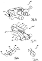
- the Fig. 2a to 2d show the actuation carriage 28 in different perspective views.
- the Aktu réellesschlitten 28 comprises two components 44, 46 in a plan view - ie in a viewing direction perpendicular to the translation direction of the Aktu réellesschlittens 28 and perpendicular to a rotational axis of the ratchet wheel 12 or to the pivot axis 18 - each have the shape of a U's.
- the component 46 is inserted in opposite directions in the component 44, so that the U's close each other.
- the components 44, 46 form a box-like unit, which - seen in a plan view - has a rectangular basic shape.
- the components 44, 46 each have side portions 44a and 46a, which are connected to each other by a transverse portion 44b and 46b. In an assembled state, the side portions 44a, 46a are in parallel against each other, while the transverse portions 44b, 46b terminate the open end of the U-shape of the respective other component 46 and 44, respectively.
- the component 44 surrounds the component 46 in the longitudinal direction of the actuation carriage 28.
- the U-shape of the component 44 completely accommodates the U-shape of the component 46.
- the two components 44, 46 are reliably connected to each other by a clamping action, which is exerted by the component 44 on the component 46.
- the side portions 44a each have at the end remote from the transverse portion 44b projections 48, on which the above-mentioned guide lugs 40 are formed. Furthermore, one of the side portions 44a has a guide projection 50, which in the already in connection with Fig. 1 described slot 42 engages to guide the Aktu réellesschlitten 28 during the translational movement and to limit the translational movement.
- Fig. 2c shows the Aktuianssschlitten 28 in an exploded view, whereby the view of the roller 32 and the intermediate roller 38 is improved. These are mounted in U-shaped slots 52 provided in the side portions 46b of the component 46.
- the component 46 has recesses 54 which serve to guide a transverse rod 54 'connected to the actuating rod 26 (see FIG Fig. 1 ).
- Fig. 2d is an opening 56 can be seen, through which the actuating rod 26 projects into the interior of the formed by the components 44, 46 rectangular base body of the Aktuianssschlittens 28 to exert a guiding function.
- Fig. 3 For example, another embodiment 20 'of the actuation mechanism is shown.
- the pawl 14 and the Rastierin 22 associated elements including the actuating rod 26 and the spring 30 are substantially similar to the corresponding in Fig. 1 shown components.
- the Aktu réellesschlitten 28 ' also two U-shaped components 44', 46 ', however, the component 44' surrounds the component 46 'is not complete, in particular the Fig. 4a to 4d can be seen.
- the side portions 44a 'of the component 44' are designed substantially shorter than the side portions 46a 'of the component 46'.
- the rollers 32, 38 are arranged in the Aktuianssschlitten 28 'in oblong holes 60, in contrast to the configuration of the Aktuianssschlittens 28.
- the component 44' When mounting the Aktuleitersschlittens 28 'the component 44' is attached to the open end of the component 46, wherein plug-in elements 58 of the component 46 'in corresponding openings (not shown) of the component 44' penetrate.
- the connection can be secured by performing a stamping process.
- FIG. 5a and 5b an embodiment 28 "of the Aktuianssschlittens shown, which in large parts, in particular with regard to the configuration of the U-shape of the components 44", 46 "substantially the Aktu réellesschlitten 28 'is similar, in particular the Figs. 6a and 6b demonstrate.
- the guidance of the actuation carriage 28 "takes place in a somewhat different manner, with only one guide hook 62 being provided which engages laterally around the guide rail 36".
- a guide groove 64 is not provided.
- the second guide hook 62 of the Aktuianssschlittens 28 ' is replaced by a guide projection 50', which engages in a slot 42 '.
Landscapes
- Engineering & Computer Science (AREA)
- General Engineering & Computer Science (AREA)
- Mechanical Engineering (AREA)
- Gear-Shifting Mechanisms (AREA)
- Lock And Its Accessories (AREA)
- Braking Arrangements (AREA)
Applications Claiming Priority (2)
| Application Number | Priority Date | Filing Date | Title |
|---|---|---|---|
| US36717010P | 2010-07-23 | 2010-07-23 | |
| DE102011018862 | 2011-04-28 |
Publications (3)
| Publication Number | Publication Date |
|---|---|
| EP2410214A2 true EP2410214A2 (fr) | 2012-01-25 |
| EP2410214A3 EP2410214A3 (fr) | 2013-02-06 |
| EP2410214B1 EP2410214B1 (fr) | 2013-09-04 |
Family
ID=44581934
Family Applications (1)
| Application Number | Title | Priority Date | Filing Date |
|---|---|---|---|
| EP11005908.6A Not-in-force EP2410214B1 (fr) | 2010-07-23 | 2011-07-19 | Mécanisme de blocage |
Country Status (4)
| Country | Link |
|---|---|
| US (1) | US8387759B2 (fr) |
| EP (1) | EP2410214B1 (fr) |
| KR (1) | KR101835560B1 (fr) |
| CN (1) | CN102345736B (fr) |
Cited By (6)
| Publication number | Priority date | Publication date | Assignee | Title |
|---|---|---|---|---|
| DE102013222843A1 (de) * | 2013-11-11 | 2015-05-13 | Schaeffler Technologies Gmbh & Co. Kg | Parksperrenvorrichtung für ein Kraftfahrzeuggetriebe sowie Kraftfahrzeuggetriebe |
| DE102017211313A1 (de) | 2017-07-04 | 2019-01-10 | Audi Ag | Blockiervorrichtung für einen Antriebsstrang eines Kraftfahrzeugs und Kraftfahrzeug mit einer solchen Blockiervorrichtung |
| EP3620689A1 (fr) * | 2018-09-07 | 2020-03-11 | DURA Automotive Holdings U.K., Ltd. | Systeme de blocage en stationnement pour une transmission d'une boite de vitesses automatique, hybride, ou electrique d'un vehicule automobile |
| EP3747713A1 (fr) * | 2019-06-03 | 2020-12-09 | Volvo Car Corporation | Agencement de verrouillage de stationnement |
| EP3943784A1 (fr) * | 2020-07-21 | 2022-01-26 | Toyota Jidosha Kabushiki Kaisha | Mécanisme de verrouillage de stationnement de véhicule |
| EP4379240A1 (fr) * | 2022-11-29 | 2024-06-05 | DURA Automotive Holdings U.K., Ltd. | Système de blocage en stationnement pour une transmission d'un réducteur ou d'une boîte de vitesses d'un véhicule automobile |
Families Citing this family (35)
| Publication number | Priority date | Publication date | Assignee | Title |
|---|---|---|---|---|
| GB201020092D0 (en) * | 2010-11-26 | 2011-01-12 | Camcon Oil Ltd | Shaft locking assembly |
| CN102720834B (zh) * | 2012-06-20 | 2015-08-05 | 浙江吉利汽车研究院有限公司杭州分公司 | 用于车辆变速器中的驻车锁止装置 |
| CN103807434B (zh) * | 2014-02-25 | 2017-11-14 | 浙江吉利控股集团有限公司 | 车辆驻车锁止装置 |
| DE102014108866B4 (de) | 2014-06-25 | 2017-04-06 | Hugo Benzing Gmbh & Co. Kg | Parksperrenbaueinheit |
| CN104534087A (zh) * | 2014-11-25 | 2015-04-22 | 重庆长安汽车股份有限公司 | 一种自动变速器驻车锁止机构 |
| US9574619B1 (en) | 2015-11-12 | 2017-02-21 | Gm Global Technology Operations, Llc | Pawl grounding clutch with synchronizer |
| DE102016015728B4 (de) | 2016-04-15 | 2025-08-28 | Hugo Benzing Gmbh & Co. Kg | Parksperren-Aktuatoreinheit |
| DE102016107003B4 (de) | 2016-04-15 | 2018-01-18 | Hugo Benzing Gmbh & Co. Kg | Parksperren-Aktuatoreinheit |
| KR101827110B1 (ko) * | 2016-05-10 | 2018-02-07 | 현대자동차주식회사 | 자동 주차 해제가 가능한 전동식 브레이크 |
| WO2018095476A1 (fr) | 2016-11-25 | 2018-05-31 | Schaeffler Technologies AG & Co. KG | Frein de stationnement pour véhicule à moteur |
| CN107606145B (zh) * | 2017-10-23 | 2019-09-03 | 北京新能源汽车股份有限公司 | P挡驻车机构和车辆 |
| CN107859739B (zh) * | 2017-10-23 | 2020-08-18 | 北京新能源汽车股份有限公司 | P挡驻车机构和车辆 |
| CN107725765B (zh) * | 2017-10-23 | 2020-06-12 | 北京新能源汽车股份有限公司 | P挡驻车机构和车辆 |
| CN107859740B (zh) * | 2017-10-23 | 2020-04-10 | 北京新能源汽车股份有限公司 | P挡驻车机构和车辆 |
| DE102018131099B4 (de) | 2017-12-13 | 2024-05-02 | Schaeffler Technologies AG & Co. KG | Parksperrengehäuse |
| WO2019169629A1 (fr) * | 2018-03-09 | 2019-09-12 | 舍弗勒技术股份两合公司 | Verrou de stationnement |
| US11708899B2 (en) * | 2018-04-11 | 2023-07-25 | Linamar Corporation | Park lock rod assembly |
| EP3620688A1 (fr) * | 2018-09-07 | 2020-03-11 | DURA Automotive Holdings U.K., Ltd. | Système de blocage en stationnement pour une transmission d'une boîte de vitesses automatique, hybride, électrique d'un véhicule automobile |
| DE102018130315A1 (de) | 2018-11-21 | 2019-10-24 | Schaeffler Technologies AG & Co. KG | Parksperre für ein Kraftfahrzeug |
| CN112912649B (zh) * | 2018-11-21 | 2022-08-09 | 舍弗勒技术股份两合公司 | 驻车锁止装置及其组装方法 |
| DE102018130765B4 (de) * | 2018-12-04 | 2020-08-06 | Schaeffler Technologies AG & Co. KG | Parksperrenvorrichtung für ein Getriebe mit einem Parksperrenrad |
| US12228185B2 (en) * | 2019-04-22 | 2025-02-18 | Hitachi Astemo, Ltd. | Disk brake |
| CN112128370A (zh) * | 2019-06-25 | 2020-12-25 | 浙江吉智新能源汽车科技有限公司 | 一种减速器驻车机构及车辆 |
| DE102019211785A1 (de) * | 2019-08-06 | 2021-02-11 | Zf Friedrichshafen Ag | Anordnung für ein Parksperrensystem |
| JP7380466B2 (ja) * | 2020-07-17 | 2023-11-15 | トヨタ自動車株式会社 | 車両用パーキングロック機構 |
| DE102020211293A1 (de) | 2020-09-09 | 2022-03-10 | Robert Bosch Gesellschaft mit beschränkter Haftung | Parksperre für Fahrzeuge |
| JP7347385B2 (ja) * | 2020-09-24 | 2023-09-20 | トヨタ自動車株式会社 | 車両用パーキングロック機構 |
| DE102020215974A1 (de) | 2020-12-16 | 2022-06-23 | Robert Bosch Gesellschaft mit beschränkter Haftung | Parksperrenrad einer Parksperre |
| KR102539994B1 (ko) * | 2021-03-15 | 2023-06-07 | 주식회사 가람 | 케이블 릴 |
| DE102021204981A1 (de) | 2021-05-18 | 2022-11-24 | Robert Bosch Gesellschaft mit beschränkter Haftung | Parksperre mit einem Parksperrenrad |
| KR102663046B1 (ko) * | 2021-11-26 | 2024-05-03 | 현대모비스 주식회사 | 차량용 브레이크 장치 |
| CN115045993B (zh) * | 2022-07-04 | 2024-01-30 | 吉利长兴自动变速器有限公司 | 驻车装置及机动车 |
| US12025222B1 (en) | 2022-07-22 | 2024-07-02 | GreenPower Motor Company | External parking lock for electric drive systems |
| US11981002B2 (en) * | 2022-10-11 | 2024-05-14 | Ford Motor Company | Parking pawl spring pre-tensioning and assembly tool system and method |
| FR3144246B1 (fr) | 2022-12-23 | 2025-10-24 | Valeo Embrayages | Mécanisme de blocage |
Family Cites Families (15)
| Publication number | Priority date | Publication date | Assignee | Title |
|---|---|---|---|---|
| JPH0347012Y2 (fr) * | 1985-09-06 | 1991-10-04 | ||
| DE10101363C1 (de) * | 2001-01-13 | 2002-10-02 | Zf Sachs Ag | Parksperrenbetätigungseinrichtung für eine Parksperrenvorrichtung eines Kraftfahrzeuges |
| DE10131735B4 (de) * | 2001-07-03 | 2009-12-17 | Volkswagen Ag | Parksperre für Fahrzeuggetriebe |
| DE10144058B4 (de) | 2001-09-07 | 2005-09-01 | Ina-Schaeffler Kg | Parksperre für ein Automatikgetriebe eines Kraftfahrzeuges |
| DE10144063B4 (de) | 2001-09-07 | 2005-09-01 | Ina-Schaeffler Kg | Parksperre für ein Automatikgetriebe eines Kraftfahrzeuges |
| DE10144056B4 (de) * | 2001-09-07 | 2005-09-01 | Ina-Schaeffler Kg | Parksperre für ein Automatikgetriebe eines Kraftfahrzeuges |
| FR2878487B1 (fr) * | 2004-11-30 | 2007-01-05 | Renault Sas | Mecanisme de verrouillage d'un arbre de transmission d'un vehicule automobile |
| DE102006030998A1 (de) * | 2006-07-05 | 2008-01-10 | Zf Friedrichshafen Ag | Betätigungselement für die Parksperre eines Getriebes und Parksperre für ein Getriebe |
| JP4333755B2 (ja) * | 2007-03-05 | 2009-09-16 | トヨタ自動車株式会社 | 車両パーキングシステム |
| JP4840598B2 (ja) * | 2007-04-27 | 2011-12-21 | 日立オートモティブシステムズ株式会社 | 電動ディスクブレーキ |
| CN201236946Y (zh) * | 2008-07-07 | 2009-05-13 | 周纯海 | 挡位限制器 |
| JP5057164B2 (ja) * | 2008-08-29 | 2012-10-24 | 日立オートモティブシステムズ株式会社 | 電動ディスクブレーキ |
| JP4752961B2 (ja) * | 2009-07-13 | 2011-08-17 | マツダ株式会社 | 変速機のパーキング装置 |
| CN201502692U (zh) * | 2009-07-21 | 2010-06-09 | 上海汽车集团股份有限公司 | 双离合器自动变速器的驻车锁止机构 |
| KR20120061665A (ko) * | 2010-12-03 | 2012-06-13 | 현대자동차주식회사 | 전기 차량용 감속기의 파킹 시스템의 레이아웃 |
-
2011
- 2011-07-19 EP EP11005908.6A patent/EP2410214B1/fr not_active Not-in-force
- 2011-07-20 US US13/186,534 patent/US8387759B2/en not_active Expired - Fee Related
- 2011-07-22 KR KR1020110073000A patent/KR101835560B1/ko not_active Expired - Fee Related
- 2011-07-25 CN CN201110208984.9A patent/CN102345736B/zh not_active Expired - Fee Related
Non-Patent Citations (1)
| Title |
|---|
| None |
Cited By (9)
| Publication number | Priority date | Publication date | Assignee | Title |
|---|---|---|---|---|
| DE102013222843A1 (de) * | 2013-11-11 | 2015-05-13 | Schaeffler Technologies Gmbh & Co. Kg | Parksperrenvorrichtung für ein Kraftfahrzeuggetriebe sowie Kraftfahrzeuggetriebe |
| WO2015067258A1 (fr) | 2013-11-11 | 2015-05-14 | Schaeffler Technologies AG & Co. KG | Système de verrouillage de stationnement pour une boîte de vitesses de véhicule automobile et boîte de vitesses de véhicule automobile |
| DE102017211313A1 (de) | 2017-07-04 | 2019-01-10 | Audi Ag | Blockiervorrichtung für einen Antriebsstrang eines Kraftfahrzeugs und Kraftfahrzeug mit einer solchen Blockiervorrichtung |
| EP3620689A1 (fr) * | 2018-09-07 | 2020-03-11 | DURA Automotive Holdings U.K., Ltd. | Systeme de blocage en stationnement pour une transmission d'une boite de vitesses automatique, hybride, ou electrique d'un vehicule automobile |
| EP3747713A1 (fr) * | 2019-06-03 | 2020-12-09 | Volvo Car Corporation | Agencement de verrouillage de stationnement |
| US11371608B2 (en) | 2019-06-03 | 2022-06-28 | Volvo Car Corporation | Park lock arrangement |
| EP3943784A1 (fr) * | 2020-07-21 | 2022-01-26 | Toyota Jidosha Kabushiki Kaisha | Mécanisme de verrouillage de stationnement de véhicule |
| EP4379240A1 (fr) * | 2022-11-29 | 2024-06-05 | DURA Automotive Holdings U.K., Ltd. | Système de blocage en stationnement pour une transmission d'un réducteur ou d'une boîte de vitesses d'un véhicule automobile |
| US12049958B2 (en) | 2022-11-29 | 2024-07-30 | Dus Operating Inc. | Parking lock system for a transmission of a motor vehicle gearbox or reduction unit |
Also Published As
| Publication number | Publication date |
|---|---|
| EP2410214B1 (fr) | 2013-09-04 |
| EP2410214A3 (fr) | 2013-02-06 |
| KR101835560B1 (ko) | 2018-04-19 |
| CN102345736B (zh) | 2015-07-29 |
| KR20120010206A (ko) | 2012-02-02 |
| CN102345736A (zh) | 2012-02-08 |
| US8387759B2 (en) | 2013-03-05 |
| US20120018259A1 (en) | 2012-01-26 |
Similar Documents
| Publication | Publication Date | Title |
|---|---|---|
| EP2410214B1 (fr) | Mécanisme de blocage | |
| DE102009059159B3 (de) | Lenksäule für ein Kraftfahrzeug | |
| DE10144063B4 (de) | Parksperre für ein Automatikgetriebe eines Kraftfahrzeuges | |
| EP2255109B1 (fr) | Système de blocage de stationnement pour une boîte de vitesses automatique | |
| DE102019101467A1 (de) | Parksperrenvorrichtung für ein Getriebe mit einem Parksperrenrad | |
| DE102010051337B4 (de) | Manuell längsverstellbarer Kraftfahrzeugsitz | |
| EP1165342A2 (fr) | Siege de vehicule | |
| DE10115034A1 (de) | Gelenkmechanismus für einen Fahrzeugsitz und Fahrzeugsitz, der mit einem solchen Mechanismus ausgestattet ist. | |
| AT511578B1 (de) | Parksperre für ein kraftfahrzeuggetriebe | |
| WO2018108204A1 (fr) | Frein de stationnement pour un véhicule automobile | |
| EP2288826B1 (fr) | PROCÉDÉ DE FABRICATION Du DISPOSITIF DE DOIGT DE CHANGEMENT DE VITESSES | |
| DE102021124656B4 (de) | Fahrzeugparkverriegelungsmechanismus | |
| EP2516209B1 (fr) | Dispositif de verrouillage, système de réglage de rail, siège de véhicule et procédé pour la fabrication dudit système de réglage de rail | |
| DE10144058B4 (de) | Parksperre für ein Automatikgetriebe eines Kraftfahrzeuges | |
| WO2018189055A1 (fr) | Colonne de direction comprenant un dispositif d'absorption d'énergie pour un véhicule à moteur | |
| EP1585880B1 (fr) | Systeme de fermeture pour fermer une porte ou un volet | |
| EP3222802B1 (fr) | Dispositif d'actionnement d'une serrure de porte coulissante d'un véhicule automobile | |
| DE10201242A1 (de) | Schubladensicherungssystem | |
| DE102006030998A1 (de) | Betätigungselement für die Parksperre eines Getriebes und Parksperre für ein Getriebe | |
| DE602004006486T2 (de) | Verriegelungsmechanismus und ein damit ausgerüstetes Schiebedach | |
| AT16957U1 (fr) | ||
| DE112023003189T5 (de) | Markisenbefestigung, Markisenzubehör und Markisenanordnungen | |
| DE102010050015B4 (de) | Feststellvorrichtung für verstellbare Kraftfahrzeuglenksäule | |
| WO2016192716A1 (fr) | Serrure de véhicule à moteur | |
| DE102013102224A1 (de) | Verriegelungseinrichtung für eine Schienenführung eines Fahrzeugsitzes |
Legal Events
| Date | Code | Title | Description |
|---|---|---|---|
| AK | Designated contracting states |
Kind code of ref document: A2 Designated state(s): AL AT BE BG CH CY CZ DE DK EE ES FI FR GB GR HR HU IE IS IT LI LT LU LV MC MK MT NL NO PL PT RO RS SE SI SK SM TR |
|
| AX | Request for extension of the european patent |
Extension state: BA ME |
|
| PUAI | Public reference made under article 153(3) epc to a published international application that has entered the european phase |
Free format text: ORIGINAL CODE: 0009012 |
|
| PUAL | Search report despatched |
Free format text: ORIGINAL CODE: 0009013 |
|
| AK | Designated contracting states |
Kind code of ref document: A3 Designated state(s): AL AT BE BG CH CY CZ DE DK EE ES FI FR GB GR HR HU IE IS IT LI LT LU LV MC MK MT NL NO PL PT RO RS SE SI SK SM TR |
|
| AX | Request for extension of the european patent |
Extension state: BA ME |
|
| RIC1 | Information provided on ipc code assigned before grant |
Ipc: F16H 63/34 20060101AFI20130103BHEP Ipc: B60T 1/06 20060101ALI20130103BHEP |
|
| 17P | Request for examination filed |
Effective date: 20130115 |
|
| GRAP | Despatch of communication of intention to grant a patent |
Free format text: ORIGINAL CODE: EPIDOSNIGR1 |
|
| RIC1 | Information provided on ipc code assigned before grant |
Ipc: F16H 63/34 20060101AFI20130315BHEP Ipc: B60T 1/06 20060101ALI20130315BHEP |
|
| INTG | Intention to grant announced |
Effective date: 20130412 |
|
| GRAS | Grant fee paid |
Free format text: ORIGINAL CODE: EPIDOSNIGR3 |
|
| GRAA | (expected) grant |
Free format text: ORIGINAL CODE: 0009210 |
|
| AK | Designated contracting states |
Kind code of ref document: B1 Designated state(s): AL AT BE BG CH CY CZ DE DK EE ES FI FR GB GR HR HU IE IS IT LI LT LU LV MC MK MT NL NO PL PT RO RS SE SI SK SM TR |
|
| REG | Reference to a national code |
Ref country code: GB Ref legal event code: FG4D Free format text: NOT ENGLISH |
|
| REG | Reference to a national code |
Ref country code: CH Ref legal event code: EP |
|
| REG | Reference to a national code |
Ref country code: AT Ref legal event code: REF Ref document number: 630721 Country of ref document: AT Kind code of ref document: T Effective date: 20130915 |
|
| REG | Reference to a national code |
Ref country code: IE Ref legal event code: FG4D Free format text: LANGUAGE OF EP DOCUMENT: GERMAN |
|
| REG | Reference to a national code |
Ref country code: DE Ref legal event code: R096 Ref document number: 502011001271 Country of ref document: DE Effective date: 20131031 |
|
| REG | Reference to a national code |
Ref country code: NL Ref legal event code: VDEP Effective date: 20130904 |
|
| PG25 | Lapsed in a contracting state [announced via postgrant information from national office to epo] |
Ref country code: LT Free format text: LAPSE BECAUSE OF FAILURE TO SUBMIT A TRANSLATION OF THE DESCRIPTION OR TO PAY THE FEE WITHIN THE PRESCRIBED TIME-LIMIT Effective date: 20130904 Ref country code: NO Free format text: LAPSE BECAUSE OF FAILURE TO SUBMIT A TRANSLATION OF THE DESCRIPTION OR TO PAY THE FEE WITHIN THE PRESCRIBED TIME-LIMIT Effective date: 20131204 Ref country code: HR Free format text: LAPSE BECAUSE OF FAILURE TO SUBMIT A TRANSLATION OF THE DESCRIPTION OR TO PAY THE FEE WITHIN THE PRESCRIBED TIME-LIMIT Effective date: 20130904 Ref country code: CY Free format text: LAPSE BECAUSE OF FAILURE TO SUBMIT A TRANSLATION OF THE DESCRIPTION OR TO PAY THE FEE WITHIN THE PRESCRIBED TIME-LIMIT Effective date: 20130807 Ref country code: SE Free format text: LAPSE BECAUSE OF FAILURE TO SUBMIT A TRANSLATION OF THE DESCRIPTION OR TO PAY THE FEE WITHIN THE PRESCRIBED TIME-LIMIT Effective date: 20130904 |
|
| REG | Reference to a national code |
Ref country code: NL Ref legal event code: VDEP Effective date: 20130904 |
|
| REG | Reference to a national code |
Ref country code: LT Ref legal event code: MG4D |
|
| PG25 | Lapsed in a contracting state [announced via postgrant information from national office to epo] |
Ref country code: LV Free format text: LAPSE BECAUSE OF FAILURE TO SUBMIT A TRANSLATION OF THE DESCRIPTION OR TO PAY THE FEE WITHIN THE PRESCRIBED TIME-LIMIT Effective date: 20130904 Ref country code: GR Free format text: LAPSE BECAUSE OF FAILURE TO SUBMIT A TRANSLATION OF THE DESCRIPTION OR TO PAY THE FEE WITHIN THE PRESCRIBED TIME-LIMIT Effective date: 20131205 Ref country code: SI Free format text: LAPSE BECAUSE OF FAILURE TO SUBMIT A TRANSLATION OF THE DESCRIPTION OR TO PAY THE FEE WITHIN THE PRESCRIBED TIME-LIMIT Effective date: 20130904 Ref country code: PL Free format text: LAPSE BECAUSE OF FAILURE TO SUBMIT A TRANSLATION OF THE DESCRIPTION OR TO PAY THE FEE WITHIN THE PRESCRIBED TIME-LIMIT Effective date: 20130904 Ref country code: FI Free format text: LAPSE BECAUSE OF FAILURE TO SUBMIT A TRANSLATION OF THE DESCRIPTION OR TO PAY THE FEE WITHIN THE PRESCRIBED TIME-LIMIT Effective date: 20130904 |
|
| PG25 | Lapsed in a contracting state [announced via postgrant information from national office to epo] |
Ref country code: CY Free format text: LAPSE BECAUSE OF FAILURE TO SUBMIT A TRANSLATION OF THE DESCRIPTION OR TO PAY THE FEE WITHIN THE PRESCRIBED TIME-LIMIT Effective date: 20130904 |
|
| PG25 | Lapsed in a contracting state [announced via postgrant information from national office to epo] |
Ref country code: RO Free format text: LAPSE BECAUSE OF FAILURE TO SUBMIT A TRANSLATION OF THE DESCRIPTION OR TO PAY THE FEE WITHIN THE PRESCRIBED TIME-LIMIT Effective date: 20130904 Ref country code: EE Free format text: LAPSE BECAUSE OF FAILURE TO SUBMIT A TRANSLATION OF THE DESCRIPTION OR TO PAY THE FEE WITHIN THE PRESCRIBED TIME-LIMIT Effective date: 20130904 Ref country code: SK Free format text: LAPSE BECAUSE OF FAILURE TO SUBMIT A TRANSLATION OF THE DESCRIPTION OR TO PAY THE FEE WITHIN THE PRESCRIBED TIME-LIMIT Effective date: 20130904 Ref country code: CZ Free format text: LAPSE BECAUSE OF FAILURE TO SUBMIT A TRANSLATION OF THE DESCRIPTION OR TO PAY THE FEE WITHIN THE PRESCRIBED TIME-LIMIT Effective date: 20130904 Ref country code: NL Free format text: LAPSE BECAUSE OF FAILURE TO SUBMIT A TRANSLATION OF THE DESCRIPTION OR TO PAY THE FEE WITHIN THE PRESCRIBED TIME-LIMIT Effective date: 20130904 Ref country code: IS Free format text: LAPSE BECAUSE OF FAILURE TO SUBMIT A TRANSLATION OF THE DESCRIPTION OR TO PAY THE FEE WITHIN THE PRESCRIBED TIME-LIMIT Effective date: 20140104 |
|
| PG25 | Lapsed in a contracting state [announced via postgrant information from national office to epo] |
Ref country code: ES Free format text: LAPSE BECAUSE OF FAILURE TO SUBMIT A TRANSLATION OF THE DESCRIPTION OR TO PAY THE FEE WITHIN THE PRESCRIBED TIME-LIMIT Effective date: 20130904 |
|
| REG | Reference to a national code |
Ref country code: DE Ref legal event code: R097 Ref document number: 502011001271 Country of ref document: DE |
|
| PG25 | Lapsed in a contracting state [announced via postgrant information from national office to epo] |
Ref country code: PT Free format text: LAPSE BECAUSE OF FAILURE TO SUBMIT A TRANSLATION OF THE DESCRIPTION OR TO PAY THE FEE WITHIN THE PRESCRIBED TIME-LIMIT Effective date: 20140106 |
|
| PLBE | No opposition filed within time limit |
Free format text: ORIGINAL CODE: 0009261 |
|
| STAA | Information on the status of an ep patent application or granted ep patent |
Free format text: STATUS: NO OPPOSITION FILED WITHIN TIME LIMIT |
|
| 26N | No opposition filed |
Effective date: 20140605 |
|
| PG25 | Lapsed in a contracting state [announced via postgrant information from national office to epo] |
Ref country code: IT Free format text: LAPSE BECAUSE OF FAILURE TO SUBMIT A TRANSLATION OF THE DESCRIPTION OR TO PAY THE FEE WITHIN THE PRESCRIBED TIME-LIMIT Effective date: 20130904 |
|
| REG | Reference to a national code |
Ref country code: DE Ref legal event code: R097 Ref document number: 502011001271 Country of ref document: DE Effective date: 20140605 |
|
| PG25 | Lapsed in a contracting state [announced via postgrant information from national office to epo] |
Ref country code: DK Free format text: LAPSE BECAUSE OF FAILURE TO SUBMIT A TRANSLATION OF THE DESCRIPTION OR TO PAY THE FEE WITHIN THE PRESCRIBED TIME-LIMIT Effective date: 20130904 |
|
| REG | Reference to a national code |
Ref country code: DE Ref legal event code: R082 Ref document number: 502011001271 Country of ref document: DE Representative=s name: RAUSCH, GABRIELE, DIPL.-PHYS. DR.RER.NAT., DE |
|
| PG25 | Lapsed in a contracting state [announced via postgrant information from national office to epo] |
Ref country code: LU Free format text: LAPSE BECAUSE OF FAILURE TO SUBMIT A TRANSLATION OF THE DESCRIPTION OR TO PAY THE FEE WITHIN THE PRESCRIBED TIME-LIMIT Effective date: 20140719 |
|
| REG | Reference to a national code |
Ref country code: CH Ref legal event code: PL |
|
| REG | Reference to a national code |
Ref country code: IE Ref legal event code: MM4A |
|
| REG | Reference to a national code |
Ref country code: FR Ref legal event code: ST Effective date: 20150331 |
|
| PG25 | Lapsed in a contracting state [announced via postgrant information from national office to epo] |
Ref country code: LI Free format text: LAPSE BECAUSE OF NON-PAYMENT OF DUE FEES Effective date: 20140731 Ref country code: CH Free format text: LAPSE BECAUSE OF NON-PAYMENT OF DUE FEES Effective date: 20140731 |
|
| PG25 | Lapsed in a contracting state [announced via postgrant information from national office to epo] |
Ref country code: FR Free format text: LAPSE BECAUSE OF NON-PAYMENT OF DUE FEES Effective date: 20140731 |
|
| PG25 | Lapsed in a contracting state [announced via postgrant information from national office to epo] |
Ref country code: IE Free format text: LAPSE BECAUSE OF NON-PAYMENT OF DUE FEES Effective date: 20140719 |
|
| REG | Reference to a national code |
Ref country code: DE Ref legal event code: R082 Ref document number: 502011001271 Country of ref document: DE Representative=s name: RAUSCH, GABRIELE, DIPL.-PHYS. DR.RER.NAT., DE Ref country code: DE Ref legal event code: R081 Ref document number: 502011001271 Country of ref document: DE Owner name: MAGNA POWERTRAIN GMBH & CO KG, AT Free format text: FORMER OWNER: MAGNA POWERTRAIN AG & CO. KG, LANNACH, AT |
|
| GBPC | Gb: european patent ceased through non-payment of renewal fee |
Effective date: 20150719 |
|
| PG25 | Lapsed in a contracting state [announced via postgrant information from national office to epo] |
Ref country code: MC Free format text: LAPSE BECAUSE OF FAILURE TO SUBMIT A TRANSLATION OF THE DESCRIPTION OR TO PAY THE FEE WITHIN THE PRESCRIBED TIME-LIMIT Effective date: 20130904 Ref country code: SM Free format text: LAPSE BECAUSE OF FAILURE TO SUBMIT A TRANSLATION OF THE DESCRIPTION OR TO PAY THE FEE WITHIN THE PRESCRIBED TIME-LIMIT Effective date: 20130904 Ref country code: GB Free format text: LAPSE BECAUSE OF NON-PAYMENT OF DUE FEES Effective date: 20150719 |
|
| PG25 | Lapsed in a contracting state [announced via postgrant information from national office to epo] |
Ref country code: MT Free format text: LAPSE BECAUSE OF FAILURE TO SUBMIT A TRANSLATION OF THE DESCRIPTION OR TO PAY THE FEE WITHIN THE PRESCRIBED TIME-LIMIT Effective date: 20130904 Ref country code: RS Free format text: LAPSE BECAUSE OF NON-PAYMENT OF DUE FEES Effective date: 20130904 Ref country code: BG Free format text: LAPSE BECAUSE OF FAILURE TO SUBMIT A TRANSLATION OF THE DESCRIPTION OR TO PAY THE FEE WITHIN THE PRESCRIBED TIME-LIMIT Effective date: 20130904 |
|
| PG25 | Lapsed in a contracting state [announced via postgrant information from national office to epo] |
Ref country code: TR Free format text: LAPSE BECAUSE OF FAILURE TO SUBMIT A TRANSLATION OF THE DESCRIPTION OR TO PAY THE FEE WITHIN THE PRESCRIBED TIME-LIMIT Effective date: 20130904 Ref country code: BE Free format text: LAPSE BECAUSE OF FAILURE TO SUBMIT A TRANSLATION OF THE DESCRIPTION OR TO PAY THE FEE WITHIN THE PRESCRIBED TIME-LIMIT Effective date: 20140731 Ref country code: HU Free format text: LAPSE BECAUSE OF FAILURE TO SUBMIT A TRANSLATION OF THE DESCRIPTION OR TO PAY THE FEE WITHIN THE PRESCRIBED TIME-LIMIT; INVALID AB INITIO Effective date: 20110719 |
|
| REG | Reference to a national code |
Ref country code: AT Ref legal event code: MM01 Ref document number: 630721 Country of ref document: AT Kind code of ref document: T Effective date: 20160719 |
|
| PG25 | Lapsed in a contracting state [announced via postgrant information from national office to epo] |
Ref country code: AT Free format text: LAPSE BECAUSE OF NON-PAYMENT OF DUE FEES Effective date: 20160719 |
|
| PG25 | Lapsed in a contracting state [announced via postgrant information from national office to epo] |
Ref country code: MK Free format text: LAPSE BECAUSE OF FAILURE TO SUBMIT A TRANSLATION OF THE DESCRIPTION OR TO PAY THE FEE WITHIN THE PRESCRIBED TIME-LIMIT Effective date: 20130904 |
|
| PG25 | Lapsed in a contracting state [announced via postgrant information from national office to epo] |
Ref country code: AL Free format text: LAPSE BECAUSE OF FAILURE TO SUBMIT A TRANSLATION OF THE DESCRIPTION OR TO PAY THE FEE WITHIN THE PRESCRIBED TIME-LIMIT Effective date: 20130904 |
|
| PGFP | Annual fee paid to national office [announced via postgrant information from national office to epo] |
Ref country code: DE Payment date: 20220720 Year of fee payment: 12 |
|
| REG | Reference to a national code |
Ref country code: DE Ref legal event code: R119 Ref document number: 502011001271 Country of ref document: DE |
|
| PG25 | Lapsed in a contracting state [announced via postgrant information from national office to epo] |
Ref country code: DE Free format text: LAPSE BECAUSE OF NON-PAYMENT OF DUE FEES Effective date: 20240201 |