EP2410308A2 - Capteur pour mesurer de grandes contraintes mécaniques dans une translation de cisaillement ou latérale - Google Patents
Capteur pour mesurer de grandes contraintes mécaniques dans une translation de cisaillement ou latérale Download PDFInfo
- Publication number
- EP2410308A2 EP2410308A2 EP11250647A EP11250647A EP2410308A2 EP 2410308 A2 EP2410308 A2 EP 2410308A2 EP 11250647 A EP11250647 A EP 11250647A EP 11250647 A EP11250647 A EP 11250647A EP 2410308 A2 EP2410308 A2 EP 2410308A2
- Authority
- EP
- European Patent Office
- Prior art keywords
- section
- sensor
- ring
- sections
- capacitive
- Prior art date
- Legal status (The legal status is an assumption and is not a legal conclusion. Google has not performed a legal analysis and makes no representation as to the accuracy of the status listed.)
- Granted
Links
Images


Classifications
-
- G—PHYSICS
- G01—MEASURING; TESTING
- G01L—MEASURING FORCE, STRESS, TORQUE, WORK, MECHANICAL POWER, MECHANICAL EFFICIENCY, OR FLUID PRESSURE
- G01L1/00—Measuring force or stress, in general
- G01L1/14—Measuring force or stress, in general by measuring variations in capacitance or inductance of electrical elements, e.g. by measuring variations of frequency of electrical oscillators
- G01L1/142—Measuring force or stress, in general by measuring variations in capacitance or inductance of electrical elements, e.g. by measuring variations of frequency of electrical oscillators using capacitors
-
- G—PHYSICS
- G01—MEASURING; TESTING
- G01B—MEASURING LENGTH, THICKNESS OR SIMILAR LINEAR DIMENSIONS; MEASURING ANGLES; MEASURING AREAS; MEASURING IRREGULARITIES OF SURFACES OR CONTOURS
- G01B7/00—Measuring arrangements characterised by the use of electric or magnetic techniques
- G01B7/16—Measuring arrangements characterised by the use of electric or magnetic techniques for measuring the deformation in a solid, e.g. by resistance strain gauge
- G01B7/22—Measuring arrangements characterised by the use of electric or magnetic techniques for measuring the deformation in a solid, e.g. by resistance strain gauge using change in capacitance
-
- G—PHYSICS
- G01—MEASURING; TESTING
- G01L—MEASURING FORCE, STRESS, TORQUE, WORK, MECHANICAL POWER, MECHANICAL EFFICIENCY, OR FLUID PRESSURE
- G01L5/00—Apparatus for, or methods of, measuring force, work, mechanical power, or torque, specially adapted for specific purposes
- G01L5/0052—Apparatus for, or methods of, measuring force, work, mechanical power, or torque, specially adapted for specific purposes measuring forces due to impact
-
- B—PERFORMING OPERATIONS; TRANSPORTING
- B64—AIRCRAFT; AVIATION; COSMONAUTICS
- B64D—EQUIPMENT FOR FITTING IN OR TO AIRCRAFT; FLIGHT SUITS; PARACHUTES; ARRANGEMENT OR MOUNTING OF POWER PLANTS OR PROPULSION TRANSMISSIONS IN AIRCRAFT
- B64D45/00—Aircraft indicators or protectors not otherwise provided for
- B64D2045/008—Devices for detecting or indicating hard landing
Definitions
- Aircraft landing gear amongst other support devices, can experience strains that might lead to catastrophic failure.
- a landing gear strut can be deformed due to strain in different directions.
- Subjective determination of when landing gear should be inspected or replaced may be over-or under-reported, leading to unnecessary inspections or a missed opportunity to inspect.
- Strain is defined as the amount of deformation per unit length of an object when a load is applied. Strain is calculated by dividing the total deformation of the original length by the original length (L):
- strain gauges are metal foil elements on polyimide film.
- the ideal strain gauge would change resistance only due to the deformations of the surface to which the gauge is attached.
- temperature, material properties, the adhesive that bonds the gauge to the surface, and the stability of the metal all affect the detected resistance.
- the sensing range of usual strain gauges is limited by maximum stress of the sensing element.
- the maximum strain limitation of both types of strain gauge and for silicon strain gauges is 3,000 micro-strain.
- FIGURE 1 shows fatigue limits on foil gauges. Even at 3,000 micro-strain they will start to shift at less than 10.000 cycles.
- the present invention provides a capacitive strain sensor for sensing shear strain or lateral displacement of a structure.
- the sensor includes a first section attached to the structure at a first location and a second section attached to the structure at a second location.
- the first section includes a capacitor plate electrically isolated from the structure and the second section includes two electrically isolated capacitive plates, both of the plates being electrically isolated from the structure.
- a flexible connector connects the first section to the second section.
- the capacitor plate of the first section is separated from the two capacitive plates of the second section by respective gaps between the first section and the two individual capacitive plates. The gaps would preferably be equal i.e. the first section concentric with the second section.
- the capacitor plate of the first section includes a core that is at least partially covered with a metallic coating.
- the two capacitive plates of the second section include a ring having an inner diameter that is greater than an outer diameter of the core. The ring is at least partially covered with two metallic coatings.
- the core and ring have dimensions along a longitudinal axis, wherein the dimension of the core is greater than the dimension of the ring.
- the ring is centered at a longitudinal center of the sensor.
- the senor includes a cavity located in at least one of the first or second sections, at least one circuit component located in the cavity, and electrical leads that connect the at least one circuit component to the capacitive plates.
- FIGURE 1 is graph of prior art results
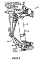
- FIGURE 2 is a perspective view of a landing gear assembly with sensors formed in accordance with the present invention
- FIGURE 3 is a side view of an exemplary sensor formed in accordance with the present invention.
- FIGURE 4 is a cross-sectional view of the sensor of FIGURE 3 ;
- FIGURE 5 is a horizontal cross-sectional view of the sensor shown in FIGURES 3 and 4 ;
- FIGURES 6-1 through 7-3 illustrate various attachment mechanisms for attaching sensors to a device under test.
- the present invention provides a capacitance-based strain sensor 26 for measuring shear strains of a structure, such as aircraft landing gear 20 at a piston 22, torque linkage 24 or other location (see FIGURE 2 ).
- the sensor 26 is a capsule having upper and lower end caps 30, 32 that allow attachment to the structure where strains are to be measured.
- the strain from the structure is transferred to internal upper and lower segments where capacitive motion sensing occurs.
- the ends of end caps 30, 32 are connected (e.g., welded) to a metal bellows 34.
- the bellows 34 allow parallel movements (along X-axis) of the end caps 30, 32.
- the bellows 34 also allow deflection in the axial (Y-axis) direction as the upper and lower end caps 30, 32 move due to structure strain.
- the sensor 26 includes three capacitive plates 46, 55-1, 56-2.
- the first capacitor plate 46 is attached to a solid core 44 that is attached (e.g., by an epoxy bead 42) to the lower end cap 32. Other attachment means may be used.
- the solid core 44 includes a continuous coating of metal on a top surface and around its circumference some distance from the top surface.
- a metal post 48 is attached to the solid core 44 at the top surface and is electrically connected to the metal coating.
- the second and third capacitive plates 56-1, 56-2 are near half circles of a metal coating on a ring 50 which are continuous with near half circles of a metal coating extending across a top surface.
- the half circles of the inner diameter and the half circles on the top of the ring are disconnected electrically forming the two separate capacitor plates 56-1, 56-2 on the inner diameter and connecting metal film on the top surface.
- the metal half circles on the top surface end short of the outer perimeter of the ring 50 such that no electrical contact is permitted with the metal structure in which the ring 50 is mounted.
- the metalized ring 50 is attached to the upper end cap 30 with an epoxy bead 52. Other attachment means may be used.
- the ring 50 is positioned with its center along a longitudinal axis (i.e., perpendicular to the x-axis) matching that of the sensor 26.
- Two metal posts 60, 62 are attached to the ring 50.
- One post 60 is positioned to electrically connect to the first plate 56-1 by mounting on the connected top surface.
- the other post 62 is positioned to electrically connect the second plate 56-2 by the same means on the respective top surface.
- the ring 50 is separated from the core 44 by a capacitive gap 58.
- the core 44 and the ring 50 are insulators (e.g., ceramic, glass, plastic or the like) before the metal coatings are applied.
- the metallization of the insulators (the core 44, ring 50) is performed by sputtering, thick film metallization, or comparable means well known in the art.
- the upper cap 30 includes a cavity for receiving circuit components, such as an Application-Specific Integrated Circuit (ASIC) 66 or other circuit components.
- ASIC Application-Specific Integrated Circuit
- Other components included in the cavity may include a battery, a radio telemetry module (i.e., wireless transmitter), an antenna for wireless communications, or other comparable components.
- Electric leads connect the ASIC 66 or other components to the capacitive plates 46, 56-1, 56-2.
- the cavity in the upper end cap 30 is sealed from the environment by a cover (not shown), which is welded to the upper surface of the upper end cap 30.
- the core 44 moves closer to one capacitor plate 56-1 or 56-2 and farther from the opposing capacitor plate 56-2 or 56-1 respectively on the ring 50.
- the two capacitances from the capacitive plates on the ring 50 are read differentially by the installed or remote electronics.
- the solid core 44 is longer than the ring 50 (extends above and below) such that longitudinal axial movement effectively does not change the capacitance reading.
- the ring 50 is mounted in the upper end cap 30 in such a manner that the lateral movement of the two end caps 30 and 32 provides relative motion of the capacitor plates in such a way that the solid core 44 moves toward one half metalized circle (56-1) and away from the other half metalized circle (56-2). For this reason, the half circles may be termed left and right as depicted In FIGURE 5 . In this orientation the attachment points of the end caps would be at either the 12 or 6 o'clock positions as depicted in FIGURE 5 . The motion of the solid core would then be left or right relative to the half circles.
- the ring 50 and the solid core 44 are positioned such that the centroid of the capacitive field is at the mid point between the end caps 30, 32.
- Such mounting allows for relative rotation between the end caps. In this case, the change in spacing between films 58 and 56 due to rotation are balanced top and bottom minimizing errors due to such rotational displacement.
- FIGURES 6-1 and 6-2 show one method for securing and aligning a strain sensor (not shown) to a structure 84 to be measured for strain.
- a mounting plate/flange 82 that is directly attached to or integral with one of the end caps includes two or more through-holes with a tapered section 94 at one end of each through-hole.
- the structure 84 includes two pin-receiving cavities 96, each having a tapered section 98 flush with the surface of the structure 84.
- the pin-receiving cavities 96 line up with the through-holes in the mounting plate/flange 82.
- a bolt/pin 86 is received through a washer 88, the through-hole, then through an eccentric tapered bushing 90 and finally a pin-receiving cavity 96.
- the tapered dowels 90 have an approximate 15° taper on both sides, matching the taper in the respective sections 94, 98.
- the two sides of each tapered dowel 90 are eccentric to each other, equivalent to the possible maximum mismatch in tolerances in machining the mating parts.
- the bushing 90 can be rotated changing the effective center distance of the bushings relative to each other.
- the eccentric tapers are slightly Larger in diameter than the tapers in the receiving cavities. This oversized condition generates an effective press fit when the fasteners are torqued into place.
- Each of the dowels 86 has an Allen hex in the center. This allows rotation of the dowel during installation, providing for the self-centering of the system.
- FIGURES 7-1 through 7-3 show bonded mounting pads 102, 104, used to position the sensor 26 onto a surface, such as the torque linkage 24.
- each end cap requires two bushings to maintain squareness of the two ends.
- at least one eccentric bushing is required to allow for center distance tolerance mismatch, as shown above.
- the eccentric bushings are inserted in the receiving cavities.
- the two mounting pads 102 and 104 with tapered receiving holes are provided.
- the two mounting pads 102 and 104 are bonded to the torque link 24 or any substrate with an adhesive.
- To align the mounting pads relative to each other first a single locating pad 100 is fastened to the mounting pads 102 and 104. This combined mounting pad assembly is brought into position on the torque linkage 24 or some other substrate. Then, an adhesive is applied between the mounting pads 102 and 104 and the torque link 24. Once the adhesive is cured, the locating pad 100 is removed and the mounting pads 102 and 104 are ready to receive the strain sensor.
- the mounting pads 102 and 104 allow the sensor 26 to be properly aligned with the torque link 24.
- an exemplary locating pad 100 is trapezoid-shaped to fit in place within the geometry of the torque link 24 or may be aligned with any feature on any substrate.
- Bolts secure flanges of the upper and lower end caps 30, 32 to the surface through the machined holes via the mounting pad holes and tapered bushings (see FIGURE 7-3 ).
- the sensor device may be side mounted on the strut piston as well or any surface where shear must be measured.
Landscapes
- Physics & Mathematics (AREA)
- General Physics & Mathematics (AREA)
- Engineering & Computer Science (AREA)
- Power Engineering (AREA)
- Measurement Of Force In General (AREA)
- Measurement Of Length, Angles, Or The Like Using Electric Or Magnetic Means (AREA)
- Force Measurement Appropriate To Specific Purposes (AREA)
Applications Claiming Priority (1)
| Application Number | Priority Date | Filing Date | Title |
|---|---|---|---|
| US12/839,061 US8607640B2 (en) | 2010-07-19 | 2010-07-19 | Sensor for measuring large mechanical strains in shear or lateral translation |
Publications (3)
| Publication Number | Publication Date |
|---|---|
| EP2410308A2 true EP2410308A2 (fr) | 2012-01-25 |
| EP2410308A3 EP2410308A3 (fr) | 2012-04-18 |
| EP2410308B1 EP2410308B1 (fr) | 2019-08-28 |
Family
ID=44764306
Family Applications (1)
| Application Number | Title | Priority Date | Filing Date |
|---|---|---|---|
| EP11250647.2A Active EP2410308B1 (fr) | 2010-07-19 | 2011-07-11 | Capteur pour mesurer de grandes contraintes mécaniques dans une translation de cisaillement ou latérale |
Country Status (3)
| Country | Link |
|---|---|
| US (1) | US8607640B2 (fr) |
| EP (1) | EP2410308B1 (fr) |
| CA (1) | CA2746162C (fr) |
Cited By (1)
| Publication number | Priority date | Publication date | Assignee | Title |
|---|---|---|---|---|
| CN108820192A (zh) * | 2018-06-13 | 2018-11-16 | 郑州秉同立智电子科技有限公司 | 一种无人机用便于更换的缓冲支架 |
Families Citing this family (6)
| Publication number | Priority date | Publication date | Assignee | Title |
|---|---|---|---|---|
| EP2554474A1 (fr) * | 2011-08-05 | 2013-02-06 | EADS Construcciones Aeronauticas, S.A. | Amortisseurs de chocs |
| EP3237833A4 (fr) * | 2014-12-22 | 2018-06-13 | Sikorsky Aircraft Corporation | Optimisation de capteur de poids à fibre optique pour train d'atterrissage |
| DE102014019546B3 (de) * | 2014-12-23 | 2016-05-04 | Samson Aktiengesellschaft | Federkörper für einen Kraftaufnehmer, wie Drehmoment- und/oder Zugkraft-/Druckkraftmesszelle |
| US9726516B2 (en) | 2015-08-06 | 2017-08-08 | Hamilton Sundstrand Corporation | Differential motion sensor |
| US10732023B2 (en) | 2016-03-24 | 2020-08-04 | Sikorsky Aircraft Corporation | Measurement system for aircraft, aircraft having the same, and method of measuring weight for aircraft |
| US11099088B2 (en) * | 2018-12-21 | 2021-08-24 | Deere & Company | Strain torque measurement system |
Family Cites Families (66)
| Publication number | Priority date | Publication date | Assignee | Title |
|---|---|---|---|---|
| US2968031A (en) | 1955-02-24 | 1961-01-10 | North American Aviation Inc | Electronic micrometer |
| US3109984A (en) * | 1958-05-28 | 1963-11-05 | Perkin Elmer Corp | Servomechanism hand control |
| US3280628A (en) * | 1964-03-31 | 1966-10-25 | Schloss Fred | High precision capacitive strain gage |
| US3433064A (en) * | 1967-05-23 | 1969-03-18 | Revere Corp America | Flexible structure for yieldably withstanding forces |
| US3471758A (en) * | 1967-09-20 | 1969-10-07 | Rosemount Eng Co Ltd | Capacitive strain sensor |
| US3783496A (en) | 1968-12-19 | 1974-01-08 | J Siler | Method of assembling members having misaligned holes |
| US3729985A (en) * | 1972-02-09 | 1973-05-01 | C Sikorra | Strain gage |
| US4269070A (en) * | 1979-09-28 | 1981-05-26 | Weico Corporation | Strain/deflection sensitive variable reluctance transducer assembly |
| US4312042A (en) | 1979-12-12 | 1982-01-19 | Sundstrand Data Control, Inc. | Weight, balance, and tire pressure detection systems |
| US4386533A (en) * | 1981-01-26 | 1983-06-07 | Deere & Company | Capacitance transducer |
| US4480480A (en) | 1981-05-18 | 1984-11-06 | Scott Science & Technology, Inc. | System for assessing the integrity of structural systems |
| EP0072634B1 (fr) | 1981-08-14 | 1986-10-08 | United Kingdom Atomic Energy Authority | Extensomètre |
| US4422341A (en) * | 1981-12-21 | 1983-12-27 | Deere & Company | Snap-in draft sensor |
| DE3239877A1 (de) | 1982-10-27 | 1984-05-03 | Interatom Internationale Atomreaktorbau Gmbh, 5060 Bergisch Gladbach | Vorrichtung zur dehnungsmessung |
| US4445386A (en) * | 1982-03-08 | 1984-05-01 | The Babcock & Wilcox Company | Hermetically sealed high temperature strain gage |
| US4510814A (en) * | 1982-04-01 | 1985-04-16 | Deere & Company | Snap-in force sensor with bellows |
| FR2545170B1 (fr) | 1983-04-29 | 1986-02-21 | Sfena | Procede de realisation de bague palier de support d'elements pour pieces cylindriques en creux ou en plein et bague palier ainsi obtenue |
| BR8707733A (pt) | 1987-04-29 | 1989-10-03 | Bell Helicopter Textron Inc | Sensor e transdutor de carga para trem de aterrissagem |
| SU1469339A1 (ru) | 1987-09-09 | 1989-03-30 | Сибирский государственный научно-исследовательский институт метрологии | Емкостный преобразователь перемещений с регулируемым межэлектродным зазором |
| US4944181A (en) * | 1988-08-30 | 1990-07-31 | Hitec Products, Inc. | Capacitive strain gage having fixed capacitor plates |
| IT1224034B (it) | 1988-12-23 | 1990-09-26 | Marelli Autronica | Sensore di deformazione ad effetto capacitivo |
| US5358637A (en) | 1989-02-18 | 1994-10-25 | Herman Finckh Maschinenfabrik Gmbh & Co. | Apparatus for sorting and deflaking fibrous suspensions |
| FR2645259B1 (fr) * | 1989-04-04 | 1994-02-11 | Thomson Csf | Capteur capacitif de deplacements et capteur d'angle de torsion comportant au moins un tel capteur capacitif |
| GB9002433D0 (en) * | 1990-02-03 | 1990-04-04 | Bloxwich Eng | Transducers |
| DE4035197A1 (de) | 1990-07-07 | 1992-01-09 | Vdo Schindling | Anordnung induktiver kraftsensoren am fahrwerk eines flugzeuges |
| US5086651A (en) * | 1990-09-19 | 1992-02-11 | Bruce Westermo | Strain monitoring apparatus and methods for use in mechanical structures subjected to stress |
| DE4112675A1 (de) | 1990-10-20 | 1992-04-23 | Vdo Schindling | Anordnung mindestens eines sensors an dem fahrwerk eines flugzeugs zur messung dessen gewichts und schwerpunktlage |
| DE69303253D1 (de) | 1992-05-22 | 1996-07-25 | Short Brothers Plc | Fehleranzeige für schliessvorrichtung |
| US5314115A (en) | 1992-05-27 | 1994-05-24 | Bombardier Inc. | Rail cross-tie for LIM transit system |
| JP3144173B2 (ja) | 1993-08-26 | 2001-03-12 | 株式会社明電舎 | 車両の駆動系試験装置 |
| CN1085332C (zh) | 1994-05-14 | 2002-05-22 | 辛纳普蒂克斯(英国)有限公司 | 位置编码器 |
| US5446666A (en) | 1994-05-17 | 1995-08-29 | The Boeing Company | Ground state-fly state transition control for unique-trim aircraft flight control system |
| US6354152B1 (en) | 1996-05-08 | 2002-03-12 | Edward Charles Herlik | Method and system to measure dynamic loads or stresses in aircraft, machines, and structures |
| FR2772342B1 (fr) | 1997-12-16 | 2000-02-18 | Aerospatiale | Ensemble propulseur a capots de soufflante munis de securites de maintien et de positionnement, pour aeronef |
| US6289289B1 (en) | 1998-12-10 | 2001-09-11 | Honeywell International Inc. | Aircraft structural fatigue monitor |
| US6575041B2 (en) * | 1999-02-05 | 2003-06-10 | Northrop Grumman Corporation | Capacitive strain gage and method |
| DE10023196C2 (de) | 2000-05-11 | 2003-04-03 | Orenstein & Koppel Ag | Vorrichtung zur Erfassung des Drehwinkels zwischen zwei Bauteilen |
| EP1970274B1 (fr) | 2000-08-04 | 2014-01-08 | Meggitt Aerospace Limited | Surveillance de l'état des freins |
| GB0126014D0 (en) | 2001-10-30 | 2001-12-19 | Sensopad Technologies Ltd | Modulated field position sensor |
| US6865690B2 (en) | 2001-06-21 | 2005-03-08 | Northrop Grumman Corporation | Voltage conditioner with embedded battery backup |
| US6676075B2 (en) | 2001-08-30 | 2004-01-13 | The Boeing Company | Airplane hard landing indication system |
| US6745153B2 (en) | 2001-11-27 | 2004-06-01 | General Motors Corporation | Data collection and manipulation apparatus and method |
| CN1692401B (zh) * | 2002-04-12 | 2011-11-16 | 雷斯里·R·奥柏梅尔 | 多轴输入转换器装置和摇杆 |
| GB2387912A (en) | 2002-04-26 | 2003-10-29 | Messier Dowty Inc | Monitoring parameters in structural components |
| US7131672B2 (en) | 2002-05-03 | 2006-11-07 | Hartwell Corporation | Latch mechanism |
| US6807853B2 (en) | 2002-05-10 | 2004-10-26 | Michelin Recherche Et Technique S.A. | System and method for generating electric power from a rotating tire's mechanical energy using piezoelectric fiber composites |
| AU2003260831C1 (en) | 2002-07-31 | 2010-01-14 | Sap Ag | Tagging with maintenance related information |
| US7552803B2 (en) | 2002-09-25 | 2009-06-30 | Goodrich Corporation | Aircraft shock strut having a fluid level monitor |
| US7490793B2 (en) | 2002-10-18 | 2009-02-17 | The Boeing Company | Wireless landing gear monitoring system |
| US6909985B2 (en) | 2002-11-27 | 2005-06-21 | Lockheed Martin Corporation | Method and apparatus for recording changes associated with acceleration of a structure |
| US20040225474A1 (en) | 2003-01-23 | 2004-11-11 | Jentek Sensors, Inc. | Damage tolerance using adaptive model-based methods |
| US6951145B2 (en) | 2003-03-24 | 2005-10-04 | Siemens Vdo Automotive Corporation | Non-contact thrust force sensor assembly |
| US6880784B1 (en) | 2003-05-08 | 2005-04-19 | Supersonic Aerospace International, Llc | Automatic takeoff thrust management system |
| US7578199B2 (en) * | 2003-08-27 | 2009-08-25 | Airbus Uk Limited | Apparatus and method suitable for measuring the displacement or load on an aircraft component |
| US7252311B2 (en) | 2003-09-17 | 2007-08-07 | Hartwell Corporation | Motor driven latch |
| US20060004499A1 (en) | 2004-06-30 | 2006-01-05 | Angela Trego | Structural health management architecture using sensor technology |
| CA2487704A1 (fr) | 2004-11-18 | 2006-05-18 | R. Kyle Schmidt | Methode et systeme de surveillance de l'etat des trains d'atterrissage |
| GB0428378D0 (en) | 2004-12-24 | 2005-02-02 | Airbus Uk Ltd | Apparatus and method for measuring loads sustained by a bearing pin |
| CA2509742A1 (fr) | 2005-06-10 | 2006-12-10 | Messier-Dowty Inc. | Systeme et methode pour determiner les evenements d'atterrissage brutal a partir des donnees de cadre de reference inertiel et du triedre de reference d'aeronef |
| ES2566046T3 (es) | 2006-03-29 | 2016-04-08 | Meggitt Sa | Dispositivo de medición de fuerza para chasis de vehículo |
| US7843363B2 (en) | 2007-07-12 | 2010-11-30 | Rosemount Aerospace Inc. | Mechanical latch locking detection sensors |
| US20090173823A1 (en) | 2008-01-07 | 2009-07-09 | Rohr, Inc. | Method and component for determining load on a latch assembly |
| US8933713B2 (en) * | 2010-07-19 | 2015-01-13 | Goodrich Corporation | Capacitive sensors for monitoring loads |
| US8359932B2 (en) * | 2010-07-19 | 2013-01-29 | Goodrich Corporation | Systems and methods for mounting landing gear strain sensors |
| US8627727B2 (en) * | 2010-07-19 | 2014-01-14 | United Technologies Corporation | Sensor for measuring large mechanical strains with fine adjustment device |
| US8286508B2 (en) * | 2010-07-19 | 2012-10-16 | Goodrich Corporation | Systems and methods for measuring angular motion |
-
2010
- 2010-07-19 US US12/839,061 patent/US8607640B2/en active Active
-
2011
- 2011-07-11 EP EP11250647.2A patent/EP2410308B1/fr active Active
- 2011-07-13 CA CA2746162A patent/CA2746162C/fr active Active
Non-Patent Citations (1)
| Title |
|---|
| None |
Cited By (1)
| Publication number | Priority date | Publication date | Assignee | Title |
|---|---|---|---|---|
| CN108820192A (zh) * | 2018-06-13 | 2018-11-16 | 郑州秉同立智电子科技有限公司 | 一种无人机用便于更换的缓冲支架 |
Also Published As
| Publication number | Publication date |
|---|---|
| EP2410308B1 (fr) | 2019-08-28 |
| EP2410308A3 (fr) | 2012-04-18 |
| CA2746162A1 (fr) | 2012-01-19 |
| US20120012699A1 (en) | 2012-01-19 |
| US8607640B2 (en) | 2013-12-17 |
| CA2746162C (fr) | 2018-07-31 |
Similar Documents
| Publication | Publication Date | Title |
|---|---|---|
| US8627727B2 (en) | Sensor for measuring large mechanical strains with fine adjustment device | |
| EP2410308B1 (fr) | Capteur pour mesurer de grandes contraintes mécaniques dans une translation de cisaillement ou latérale | |
| US8359932B2 (en) | Systems and methods for mounting landing gear strain sensors | |
| US10209151B2 (en) | Torque sensor | |
| CN105588669B (zh) | 一种轴销式三向测力传感器 | |
| CN102879131B (zh) | 力传感器组件和用于装配力传感器组件的方法 | |
| US20190275681A1 (en) | Torque sensor device and method for detecting torques | |
| US8933713B2 (en) | Capacitive sensors for monitoring loads | |
| EP2006653A1 (fr) | Palier pour roue equipe d'un capteur | |
| US9548643B2 (en) | Load cell on EMA housing with trim resistors | |
| WO2011069515A2 (fr) | Capteurs de force-couple multiaxiaux | |
| EP2441671B1 (fr) | Capteurs capacitifs pour surveiller des charges sur le train d'atterrissage d'un aéronef | |
| US20090084197A1 (en) | Method and apparatus for mounting a sensor | |
| US7819017B2 (en) | Dynamometer element | |
| CN112959050B (zh) | 一种单极板电容传感器的装配装置和装配方法 | |
| CN109724738B (zh) | 一种空间在轨捕获过程运动绳系张力测量装置 | |
| CN112556902B (zh) | 双量程测力传感器及制造方法 | |
| CN113295406B (zh) | 一种分动器总成离合器轴向压力标定装置及其标定方法 | |
| CN115534921B (zh) | 一种高铁刹车系统的数字传感器 | |
| CN114858334A (zh) | 火箭发动机推力矢量测量装置以及推力矢量测量方法 | |
| CN119223507A (zh) | 扭矩传感器及其使用方法 | |
| CN108931226A (zh) | 高精密测量角度编码器结构 |
Legal Events
| Date | Code | Title | Description |
|---|---|---|---|
| 17P | Request for examination filed |
Effective date: 20110722 |
|
| AK | Designated contracting states |
Kind code of ref document: A2 Designated state(s): AL AT BE BG CH CY CZ DE DK EE ES FI FR GB GR HR HU IE IS IT LI LT LU LV MC MK MT NL NO PL PT RO RS SE SI SK SM TR |
|
| AX | Request for extension of the european patent |
Extension state: BA ME |
|
| PUAI | Public reference made under article 153(3) epc to a published international application that has entered the european phase |
Free format text: ORIGINAL CODE: 0009012 |
|
| PUAL | Search report despatched |
Free format text: ORIGINAL CODE: 0009013 |
|
| PUAF | Information related to the publication of a search report (a3 document) modified or deleted |
Free format text: ORIGINAL CODE: 0009199SEPU |
|
| AK | Designated contracting states |
Kind code of ref document: A3 Designated state(s): AL AT BE BG CH CY CZ DE DK EE ES FI FR GB GR HR HU IE IS IT LI LT LU LV MC MK MT NL NO PL PT RO RS SE SI SK SM TR |
|
| AX | Request for extension of the european patent |
Extension state: BA ME |
|
| RIC1 | Information provided on ipc code assigned before grant |
Ipc: G01L 1/14 20060101AFI20120131BHEP Ipc: B64C 25/00 20060101ALI20120131BHEP Ipc: G01G 19/07 20060101ALI20120131BHEP Ipc: G01L 5/00 20060101ALI20120131BHEP Ipc: G01B 7/16 20060101ALI20120131BHEP |
|
| D17D | Deferred search report published (deleted) | ||
| PUAL | Search report despatched |
Free format text: ORIGINAL CODE: 0009013 |
|
| AK | Designated contracting states |
Kind code of ref document: A3 Designated state(s): AL AT BE BG CH CY CZ DE DK EE ES FI FR GB GR HR HU IE IS IT LI LT LU LV MC MK MT NL NO PL PT RO RS SE SI SK SM TR |
|
| AX | Request for extension of the european patent |
Extension state: BA ME |
|
| RIC1 | Information provided on ipc code assigned before grant |
Ipc: B64C 25/00 20060101ALI20120309BHEP Ipc: G01L 1/14 20060101AFI20120309BHEP Ipc: G01B 7/16 20060101ALI20120309BHEP Ipc: G01L 5/00 20060101ALI20120309BHEP Ipc: G01G 19/07 20060101ALI20120309BHEP |
|
| 17Q | First examination report despatched |
Effective date: 20151210 |
|
| GRAP | Despatch of communication of intention to grant a patent |
Free format text: ORIGINAL CODE: EPIDOSNIGR1 |
|
| STAA | Information on the status of an ep patent application or granted ep patent |
Free format text: STATUS: GRANT OF PATENT IS INTENDED |
|
| INTG | Intention to grant announced |
Effective date: 20190124 |
|
| RAP1 | Party data changed (applicant data changed or rights of an application transferred) |
Owner name: GOODRICH CORPORATION |
|
| RIN1 | Information on inventor provided before grant (corrected) |
Inventor name: ERIKSEN, ODD HARALD STEEN |
|
| GRAS | Grant fee paid |
Free format text: ORIGINAL CODE: EPIDOSNIGR3 |
|
| GRAA | (expected) grant |
Free format text: ORIGINAL CODE: 0009210 |
|
| STAA | Information on the status of an ep patent application or granted ep patent |
Free format text: STATUS: THE PATENT HAS BEEN GRANTED |
|
| AK | Designated contracting states |
Kind code of ref document: B1 Designated state(s): AL AT BE BG CH CY CZ DE DK EE ES FI FR GB GR HR HU IE IS IT LI LT LU LV MC MK MT NL NO PL PT RO RS SE SI SK SM TR |
|
| REG | Reference to a national code |
Ref country code: GB Ref legal event code: FG4D |
|
| REG | Reference to a national code |
Ref country code: CH Ref legal event code: EP |
|
| REG | Reference to a national code |
Ref country code: DE Ref legal event code: R096 Ref document number: 602011061571 Country of ref document: DE |
|
| REG | Reference to a national code |
Ref country code: AT Ref legal event code: REF Ref document number: 1172993 Country of ref document: AT Kind code of ref document: T Effective date: 20190915 |
|
| REG | Reference to a national code |
Ref country code: IE Ref legal event code: FG4D |
|
| REG | Reference to a national code |
Ref country code: NL Ref legal event code: MP Effective date: 20190828 |
|
| REG | Reference to a national code |
Ref country code: LT Ref legal event code: MG4D |
|
| PG25 | Lapsed in a contracting state [announced via postgrant information from national office to epo] |
Ref country code: PT Free format text: LAPSE BECAUSE OF FAILURE TO SUBMIT A TRANSLATION OF THE DESCRIPTION OR TO PAY THE FEE WITHIN THE PRESCRIBED TIME-LIMIT Effective date: 20191230 Ref country code: FI Free format text: LAPSE BECAUSE OF FAILURE TO SUBMIT A TRANSLATION OF THE DESCRIPTION OR TO PAY THE FEE WITHIN THE PRESCRIBED TIME-LIMIT Effective date: 20190828 Ref country code: LT Free format text: LAPSE BECAUSE OF FAILURE TO SUBMIT A TRANSLATION OF THE DESCRIPTION OR TO PAY THE FEE WITHIN THE PRESCRIBED TIME-LIMIT Effective date: 20190828 Ref country code: NL Free format text: LAPSE BECAUSE OF FAILURE TO SUBMIT A TRANSLATION OF THE DESCRIPTION OR TO PAY THE FEE WITHIN THE PRESCRIBED TIME-LIMIT Effective date: 20190828 Ref country code: BG Free format text: LAPSE BECAUSE OF FAILURE TO SUBMIT A TRANSLATION OF THE DESCRIPTION OR TO PAY THE FEE WITHIN THE PRESCRIBED TIME-LIMIT Effective date: 20191128 Ref country code: NO Free format text: LAPSE BECAUSE OF FAILURE TO SUBMIT A TRANSLATION OF THE DESCRIPTION OR TO PAY THE FEE WITHIN THE PRESCRIBED TIME-LIMIT Effective date: 20191128 Ref country code: SE Free format text: LAPSE BECAUSE OF FAILURE TO SUBMIT A TRANSLATION OF THE DESCRIPTION OR TO PAY THE FEE WITHIN THE PRESCRIBED TIME-LIMIT Effective date: 20190828 Ref country code: HR Free format text: LAPSE BECAUSE OF FAILURE TO SUBMIT A TRANSLATION OF THE DESCRIPTION OR TO PAY THE FEE WITHIN THE PRESCRIBED TIME-LIMIT Effective date: 20190828 |
|
| PG25 | Lapsed in a contracting state [announced via postgrant information from national office to epo] |
Ref country code: IS Free format text: LAPSE BECAUSE OF FAILURE TO SUBMIT A TRANSLATION OF THE DESCRIPTION OR TO PAY THE FEE WITHIN THE PRESCRIBED TIME-LIMIT Effective date: 20191228 Ref country code: GR Free format text: LAPSE BECAUSE OF FAILURE TO SUBMIT A TRANSLATION OF THE DESCRIPTION OR TO PAY THE FEE WITHIN THE PRESCRIBED TIME-LIMIT Effective date: 20191129 Ref country code: RS Free format text: LAPSE BECAUSE OF FAILURE TO SUBMIT A TRANSLATION OF THE DESCRIPTION OR TO PAY THE FEE WITHIN THE PRESCRIBED TIME-LIMIT Effective date: 20190828 Ref country code: AL Free format text: LAPSE BECAUSE OF FAILURE TO SUBMIT A TRANSLATION OF THE DESCRIPTION OR TO PAY THE FEE WITHIN THE PRESCRIBED TIME-LIMIT Effective date: 20190828 Ref country code: LV Free format text: LAPSE BECAUSE OF FAILURE TO SUBMIT A TRANSLATION OF THE DESCRIPTION OR TO PAY THE FEE WITHIN THE PRESCRIBED TIME-LIMIT Effective date: 20190828 Ref country code: ES Free format text: LAPSE BECAUSE OF FAILURE TO SUBMIT A TRANSLATION OF THE DESCRIPTION OR TO PAY THE FEE WITHIN THE PRESCRIBED TIME-LIMIT Effective date: 20190828 |
|
| REG | Reference to a national code |
Ref country code: AT Ref legal event code: MK05 Ref document number: 1172993 Country of ref document: AT Kind code of ref document: T Effective date: 20190828 |
|
| PG25 | Lapsed in a contracting state [announced via postgrant information from national office to epo] |
Ref country code: TR Free format text: LAPSE BECAUSE OF FAILURE TO SUBMIT A TRANSLATION OF THE DESCRIPTION OR TO PAY THE FEE WITHIN THE PRESCRIBED TIME-LIMIT Effective date: 20190828 |
|
| PG25 | Lapsed in a contracting state [announced via postgrant information from national office to epo] |
Ref country code: PL Free format text: LAPSE BECAUSE OF FAILURE TO SUBMIT A TRANSLATION OF THE DESCRIPTION OR TO PAY THE FEE WITHIN THE PRESCRIBED TIME-LIMIT Effective date: 20190828 Ref country code: DK Free format text: LAPSE BECAUSE OF FAILURE TO SUBMIT A TRANSLATION OF THE DESCRIPTION OR TO PAY THE FEE WITHIN THE PRESCRIBED TIME-LIMIT Effective date: 20190828 Ref country code: AT Free format text: LAPSE BECAUSE OF FAILURE TO SUBMIT A TRANSLATION OF THE DESCRIPTION OR TO PAY THE FEE WITHIN THE PRESCRIBED TIME-LIMIT Effective date: 20190828 Ref country code: EE Free format text: LAPSE BECAUSE OF FAILURE TO SUBMIT A TRANSLATION OF THE DESCRIPTION OR TO PAY THE FEE WITHIN THE PRESCRIBED TIME-LIMIT Effective date: 20190828 Ref country code: IT Free format text: LAPSE BECAUSE OF FAILURE TO SUBMIT A TRANSLATION OF THE DESCRIPTION OR TO PAY THE FEE WITHIN THE PRESCRIBED TIME-LIMIT Effective date: 20190828 Ref country code: RO Free format text: LAPSE BECAUSE OF FAILURE TO SUBMIT A TRANSLATION OF THE DESCRIPTION OR TO PAY THE FEE WITHIN THE PRESCRIBED TIME-LIMIT Effective date: 20190828 |
|
| PG25 | Lapsed in a contracting state [announced via postgrant information from national office to epo] |
Ref country code: SM Free format text: LAPSE BECAUSE OF FAILURE TO SUBMIT A TRANSLATION OF THE DESCRIPTION OR TO PAY THE FEE WITHIN THE PRESCRIBED TIME-LIMIT Effective date: 20190828 Ref country code: SK Free format text: LAPSE BECAUSE OF FAILURE TO SUBMIT A TRANSLATION OF THE DESCRIPTION OR TO PAY THE FEE WITHIN THE PRESCRIBED TIME-LIMIT Effective date: 20190828 Ref country code: CZ Free format text: LAPSE BECAUSE OF FAILURE TO SUBMIT A TRANSLATION OF THE DESCRIPTION OR TO PAY THE FEE WITHIN THE PRESCRIBED TIME-LIMIT Effective date: 20190828 Ref country code: IS Free format text: LAPSE BECAUSE OF FAILURE TO SUBMIT A TRANSLATION OF THE DESCRIPTION OR TO PAY THE FEE WITHIN THE PRESCRIBED TIME-LIMIT Effective date: 20200224 |
|
| REG | Reference to a national code |
Ref country code: DE Ref legal event code: R097 Ref document number: 602011061571 Country of ref document: DE |
|
| PLBE | No opposition filed within time limit |
Free format text: ORIGINAL CODE: 0009261 |
|
| STAA | Information on the status of an ep patent application or granted ep patent |
Free format text: STATUS: NO OPPOSITION FILED WITHIN TIME LIMIT |
|
| PG2D | Information on lapse in contracting state deleted |
Ref country code: IS |
|
| 26N | No opposition filed |
Effective date: 20200603 |
|
| PG25 | Lapsed in a contracting state [announced via postgrant information from national office to epo] |
Ref country code: SI Free format text: LAPSE BECAUSE OF FAILURE TO SUBMIT A TRANSLATION OF THE DESCRIPTION OR TO PAY THE FEE WITHIN THE PRESCRIBED TIME-LIMIT Effective date: 20190828 |
|
| PG25 | Lapsed in a contracting state [announced via postgrant information from national office to epo] |
Ref country code: MC Free format text: LAPSE BECAUSE OF FAILURE TO SUBMIT A TRANSLATION OF THE DESCRIPTION OR TO PAY THE FEE WITHIN THE PRESCRIBED TIME-LIMIT Effective date: 20190828 |
|
| REG | Reference to a national code |
Ref country code: CH Ref legal event code: PL |
|
| GBPC | Gb: european patent ceased through non-payment of renewal fee |
Effective date: 20200711 |
|
| REG | Reference to a national code |
Ref country code: BE Ref legal event code: MM Effective date: 20200731 |
|
| PG25 | Lapsed in a contracting state [announced via postgrant information from national office to epo] |
Ref country code: CH Free format text: LAPSE BECAUSE OF NON-PAYMENT OF DUE FEES Effective date: 20200731 Ref country code: LI Free format text: LAPSE BECAUSE OF NON-PAYMENT OF DUE FEES Effective date: 20200731 Ref country code: LU Free format text: LAPSE BECAUSE OF NON-PAYMENT OF DUE FEES Effective date: 20200711 Ref country code: GB Free format text: LAPSE BECAUSE OF NON-PAYMENT OF DUE FEES Effective date: 20200711 |
|
| PG25 | Lapsed in a contracting state [announced via postgrant information from national office to epo] |
Ref country code: BE Free format text: LAPSE BECAUSE OF NON-PAYMENT OF DUE FEES Effective date: 20200731 |
|
| PG25 | Lapsed in a contracting state [announced via postgrant information from national office to epo] |
Ref country code: IE Free format text: LAPSE BECAUSE OF NON-PAYMENT OF DUE FEES Effective date: 20200711 |
|
| PG25 | Lapsed in a contracting state [announced via postgrant information from national office to epo] |
Ref country code: MT Free format text: LAPSE BECAUSE OF FAILURE TO SUBMIT A TRANSLATION OF THE DESCRIPTION OR TO PAY THE FEE WITHIN THE PRESCRIBED TIME-LIMIT Effective date: 20190828 Ref country code: CY Free format text: LAPSE BECAUSE OF FAILURE TO SUBMIT A TRANSLATION OF THE DESCRIPTION OR TO PAY THE FEE WITHIN THE PRESCRIBED TIME-LIMIT Effective date: 20190828 |
|
| PG25 | Lapsed in a contracting state [announced via postgrant information from national office to epo] |
Ref country code: MK Free format text: LAPSE BECAUSE OF FAILURE TO SUBMIT A TRANSLATION OF THE DESCRIPTION OR TO PAY THE FEE WITHIN THE PRESCRIBED TIME-LIMIT Effective date: 20190828 |
|
| P01 | Opt-out of the competence of the unified patent court (upc) registered |
Effective date: 20230522 |
|
| PGFP | Annual fee paid to national office [announced via postgrant information from national office to epo] |
Ref country code: FR Payment date: 20250620 Year of fee payment: 15 |
|
| PGFP | Annual fee paid to national office [announced via postgrant information from national office to epo] |
Ref country code: DE Payment date: 20250620 Year of fee payment: 15 |