EP2411269B1 - Surface portante à volet hypersustentateur - Google Patents
Surface portante à volet hypersustentateur Download PDFInfo
- Publication number
- EP2411269B1 EP2411269B1 EP10711352.4A EP10711352A EP2411269B1 EP 2411269 B1 EP2411269 B1 EP 2411269B1 EP 10711352 A EP10711352 A EP 10711352A EP 2411269 B1 EP2411269 B1 EP 2411269B1
- Authority
- EP
- European Patent Office
- Prior art keywords
- axle shaft
- lever
- axis
- wing
- rotation
- Prior art date
- Legal status (The legal status is an assumption and is not a legal conclusion. Google has not performed a legal analysis and makes no representation as to the accuracy of the status listed.)
- Active
Links
- 230000007246 mechanism Effects 0.000 claims description 64
- 230000008878 coupling Effects 0.000 claims description 10
- 238000010168 coupling process Methods 0.000 claims description 10
- 238000005859 coupling reaction Methods 0.000 claims description 10
- 210000001503 joint Anatomy 0.000 description 10
- 238000006073 displacement reaction Methods 0.000 description 2
- 230000000712 assembly Effects 0.000 description 1
- 238000000429 assembly Methods 0.000 description 1
- 230000015572 biosynthetic process Effects 0.000 description 1
- 230000001419 dependent effect Effects 0.000 description 1
- 230000000694 effects Effects 0.000 description 1
Images



Classifications
-
- B—PERFORMING OPERATIONS; TRANSPORTING
- B64—AIRCRAFT; AVIATION; COSMONAUTICS
- B64C—AEROPLANES; HELICOPTERS
- B64C9/00—Adjustable control surfaces or members, e.g. rudders
- B64C9/14—Adjustable control surfaces or members, e.g. rudders forming slots
- B64C9/22—Adjustable control surfaces or members, e.g. rudders forming slots at the front of the wing
-
- B—PERFORMING OPERATIONS; TRANSPORTING
- B64—AIRCRAFT; AVIATION; COSMONAUTICS
- B64C—AEROPLANES; HELICOPTERS
- B64C9/00—Adjustable control surfaces or members, e.g. rudders
- B64C9/02—Mounting or supporting thereof
-
- B—PERFORMING OPERATIONS; TRANSPORTING
- B64—AIRCRAFT; AVIATION; COSMONAUTICS
- B64C—AEROPLANES; HELICOPTERS
- B64C9/00—Adjustable control surfaces or members, e.g. rudders
- B64C9/14—Adjustable control surfaces or members, e.g. rudders forming slots
- B64C9/16—Adjustable control surfaces or members, e.g. rudders forming slots at the rear of the wing
Definitions
- the invention relates to a wing with a main wing and a movably arranged on this high-lift flap.
- the DE 103 28 717 B3 describes an actuator for adjusting a trailing edge flap of an aircraft relative to a main wing thereof.
- the Betsch Trentsein-direction is formed of two pyramidal gear assemblies, each having two mechanically connected in series pyramid gear. Of these, a first pyramid gear with the supporting structure of the wing and a second pyramid gear is connected to the trailing edge flap.
- a wing having a main wing and a high lift flap is known, which is arranged by means of at least two juxtaposed in the spanwise direction of the wing side adjustment mechanisms on the wing movable, each of the adjustment mechanisms is formed from articulated levers to form three hinge axes whose directions to meet in a common pole.
- the object of the invention is to provide a wing with a main wing and a movably arranged on this high-lift flap whose adjustment is kinematically optimized.
- the first, second and third axes of rotation run through a common pole, which is fixed in the adjustment of the high-lift flap with respect to the position of the main wing.
- a joint intermediate part is arranged with a base body and at least a first and a second axle receiving spaced in the transverse direction of the body and is formed such that two axis parts running in the longitudinal direction of the body Transverse direction of the body spaced from each other are rotatably received.
- the joint intermediate part with the first axle receiving a second axis part to form the second axis of rotation and with the second Achsfact a fourth axis part to form a fourth axis of rotation for coupling the second adjusting lever and the high-lift flap to the joint intermediate part rotatably supports an axial distance between the second axis of rotation and the fourth axis.
- the base body is formed in one piece.
- the base body is formed in two pieces from two intermediate levers, wherein each intermediate lever each having a pair of Achsaufêtn.
- the intermediate joint part is formed such that the first axis of rotation and the fourth axis of rotation or second axis of rotation and the respective fourth axis of rotation are each parallel to each other.
- the joint intermediate part is formed from a base body and disposed thereon two pairs of axle mounts, each having a first and a second axle receiving each for forming a pivot bearing with an axis, wherein the respective first axle mounts an axle for Forming the first axis of rotation or the second axis of rotation rotatably receives and wherein the respective second axle mount rotatably receives axle parts for forming the respective fourth axis of rotation and the first and the second axle each receiving a pair of axle shots from each other in the transverse direction of the intermediate joint part to form the axial distance between The respective axes of rotation are spaced.
- axle mounts of the intermediate joint part can be arranged offset to one another in the longitudinal direction of the same.
- the main body of the joint intermediate part is formed from two extending along the transverse direction intermediate levers, wherein: the first intermediate lever a pair of axle mounts with a first and a second each formed as a spherical bearing axle each for receiving an axle section for coupling the intermediate joint part at a first end to the high lift flap or the main wing and at a second end to the first adjustment lever or the second adjustment lever, and wherein the second intermediate lever at the first end rotationally fixed to the high lift flap or the Main wing is connected and at the second end designed as a spherical bearing axle receptacle, with the second end of the second intermediate lever is coupled to an axle portion of the first adjusting lever or of the second adjusting lever.
- the main body of the joint intermediate part is formed from two extending along the transverse direction intermediate levers, wherein: the first intermediate lever a pair of axle mounts with a first and a second each formed as a spherical bearing axle each for receiving an axle section for coupling the intermediate joint part at a first end to the first adjusting lever or the second adjusting lever and at a second end to the high-lift flap or the main wing, and wherein the second intermediate lever at the first end rotationally fixed to the first adjusting lever or is connected to the second adjusting lever and at the second end formed as a spherical bearing axle receptacle, with which the second end of the second intermediate lever is coupled to an axle portion of the high-lift flap or the main wing.
- the main body of the joint intermediate part is formed of two extending along the transverse direction intermediate levers, wherein: the first intermediate lever in the transverse direction spaced apart axle mounts with a first and a second each formed as a spherical bearing axle respectively for rotatably receiving an axle portion, wherein the intermediate joint part is coupled at a first end to an axle portion of the high lift door or an axle portion of the main wing and at a second end to an axle portion of the first shift lever or the second shift lever, and wherein the second intermediate lever a A pair of spaced apart in the transverse direction axle mounts with at least a first designed as a spherical bearing axle and at least one second designed as a non-spherical bearing axle each to rotate baren receiving an axle portion, wherein the intermediate joint part is coupled at a first end with an axis portion of the high lift flap or an axis portion of the main wing and at a second end with an axis portion of the first
- the second intermediate lever of the intermediate joint part in the transverse direction spaced axle mounts with a first axle and two second axle mounts, which are each formed as non-spherical bearings and for rotatably receiving an axle portion, wherein the joint intermediate part coupled at a first end to an axle portion of the high lift door or an axle portion of the main wing and at a second end to an axle portion of the first shift lever or the second shift lever.
- the second intermediate lever of the intermediate joint part in the transverse direction spaced axle mounts with two first axle and a second axle, which are each formed as a non-spherical bearings and for rotatably receiving an axle portion, wherein the joint intermediate part of a first end coupled to an axle portion of the high lift door or an axle portion of the main wing and at a second end to an axle portion of the first shift lever or the second shift lever.
- the high-lift flap may in particular be a slat.
- the slat may be a Krügerklappe, which is located in its retracted position at the bottom of the main wing.
- the slat may be a slat.
- the high-lift flap is a trailing edge flap.
- the drive device may be formed according to the invention of a linear drive.
- the drive device may be formed from a rotary drive.
- the wing has a stop device for limiting the maximum extension position of the high lift flap and the stop device is formed with a stop lever acting between the first and the second adjusting lever, which is integral with the first adjusting lever or with the second adjusting lever and is formed as an extension thereof in the direction of the second axis or the first axis and which is designed such that the free end of Stop lever can be brought into a stop position with a support device on the second lever or the first lever to define the maximum extension position of the respective adjustment mechanism.
- the wing has a stop device for limiting the maximum extension position of the high lift flap and the stop device is formed with a stop lever to limit the maximum extension position of the high lift flap, which is integral with the first lever or with a fitting of Main wing and as an extension thereof is formed towards the fitting of the main wing or the third joint and which is designed such that the free end of the stop lever can be brought into a stop position with the fitting of the main wing or the first lever to the maximum extended position to define the respective adjustment mechanism.
- the wing has a stop device for limiting the maximum extension position of the high lift flap and the stop device is formed with a stop lever to limit the maximum extension position of the high lift flap, which is integral with the second lever or with a fitting of the high lift flap and as an extension the same is formed in the direction of the fitting of the high lift flap or the third joint and which is designed such that the free end of the stop lever can be brought into a stop position with the fitting of the high lift flap or the second lever to the maximum extension position of the respective adjustment mechanism define.
- the stop device can be designed in particular such that it limits a maximum extension position of the slat, in which the directions of action of the adjusting levers relative to one another have an angle ( ⁇ ) of less than 180 degrees. It can also be provided that cooperates with the stop lever, a spring device to a restoring force on the adjusting mechanism exercise and / or cushion the achievement of the maximum extension position of the respective adjustment mechanism.
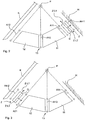
- FIG. 1 schematically represents an embodiment of the wing according to the invention T with a main wing H a high-lift flap K.
- the high-lift flap K is arranged by means of an adjusting device 10 with at least two adjustment mechanisms 10a, 10b on the main wing H, in the spanwise direction H-SW of the main wing H. or in the spanwise direction K-SW of the high-lift flap K are arranged side by side.
- the high-lift flap K can according to the invention be a slat K1 or a trailing edge flap.
- the high-lift flap K a slat K1, which is designed as a slat.
- the slat K1 can also be a Krüger flap, which is located in its retracted position on the underside of the main wing H.
- the slat K1 is in the FIG. 1 shown in an extended position.
- two adjusting mechanisms 10a, 10b are shown on the illustrated section of the main wing H and the slat K1. Also is in the FIG.
- the high-lift flap or the slat is movably arranged by means of at least two adjustment mechanisms on the main wing between a retracted and an extended position.
- the slat shown is shown in an extended position, wherein the extended position shown is not the maximum extension position of the high-lift flap K and the slat K1.
- the directions of the first, second and third axes of rotation A11, A12 and A13 of the first adjusting mechanism 10a meet in a common pole P fixed in the displacement of the high-lift flap K with respect to the position of the main wing, i. is independent of the high-lift flap K or the slat K1.
- the high-lift flap K relative to the main wing H on a movement with a part-circular path of movement when it is moved from its retracted to the extended position and vice versa.
- the directions of the first, second and third axes of rotation A1, A2 and A3 of the second adjusting mechanism 10b meet in a common pole P fixed in the displacement of the high-lift flap K with respect to the position of the main wing, i. is independent of the high-lift flap K or the slat K1.
- the first adjusting mechanism 10a is illustrated schematically for illustrating the kinematic concept.
- the drive device acts on one of the adjusting lever and this adjusted to adjust the adjustment.
- the drive device is designed as a linear drive and be coupled to the joints of the first and second adjusting mechanism, with each connect the first and the second adjusting an adjusting mechanism with each other.
- the drive device is designed as a linear drive and is arranged between two adjusting levers of different adjustment mechanisms 1, 2 and coupled thereto. By moving apart and contracting (contracting) of the linear drive of the drive device the two are pressed apart or together by this coupled lever and thereby moves the adjustment in a retracted or extended state. In this case, the drive device between a first adjusting lever of the first adjusting mechanism and a second adjusting lever of the second adjusting mechanism and vice versa be coupled.
- At least one adjusting mechanism 10a, 10b of an adjusting device 10 uses a joint intermediate part Z with a basic body Z1.
- the joint intermediate part Z is used on exactly one adjusting mechanism 10a, 10b of an adjusting device 10.
- the main body Z1 may be formed in one or more parts and in particular two parts.
- the main body Z1 has at least one pair of axle receptacles, which are arranged spaced apart as seen in a transverse direction Z-L2 and formed such that two axis parts extending transversely to the longitudinal direction Z-L1 of the main body G transverse to the transverse direction Z-L2 Main body G spaced from each other are rotatably received.
- the axial parts are in the same axis parts for connecting the intermediate joint part Z to the main wing H (FIG. FIG. 2 ) or with the high-lift flap ( FIG. 3 ) provided on one side of the intermediate joint part Z and with the first 11, 21 and second 12, 22 adjusting lever on the other side of the joint intermediate part Z. This way is between the second
- the intermediate joint part Z with at least one first axle mount rotatably supports a first axle part forming the first axis of rotation A11, A21 and the second axle receiving a fourth axis part forming a fourth axis of rotation A4-1 for coupling the first one Adjusting lever 11, 21 and the main wing H to the joint intermediate part Z with an axial distance D between the first axis of rotation A11, A21 and the fourth axis A4-1.
- the intermediate joint part Z with the first axle receiving a second axis part forming the second axis of rotation A12, A22 and the second Achs a fourth axis part to form a fourth axis of rotation A4-2 for coupling the second adjustment lever 12th , 22 and the high-lift flap K to the intermediate joint part Z with an axial distance D between the second axis of rotation A12, A22 and the fourth axis A4-2.
- the intermediate joint part Z may be formed such that the first axis of rotation A11, A21 and the fourth axis of rotation A4-1 or second axis of rotation A12, A22 and the respective fourth axis of rotation A4-2 each parallel to each other.
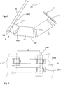
- FIG. 4 an embodiment of the inventively provided joint intermediate part Z is shown, which is formed from a base body Z1 and a first pair of axle receptacles 101, 103 arranged thereon and a second pair of axle receptacles 102, 104.
- Each pair of axle receptacles thus has a first 101 and 102 and a second axle receptacle 103 and 104 respectively for forming a pivot bearing with an axis (in the FIG. 4 not shown).
- the first and second axle receptacle lies with respect to the longitudinal direction Z-L1 at mutually opposite sides of the main body Z1.
- the respective first axle receptacles 101, 102 rotatably receive an axle part for forming the first rotational axis A11, A21 or the second rotational axis A12, A22.
- an embodiment is shown in which the first axle receptacles 101, 102 an axle part for forming the first axis of rotation A11 take up.
- the respective second axle mountings rotatably receive axle parts for forming the respective fourth rotation axis A4-1 or A4-2 (depending on the arrangement in the adjustment mechanism).
- the second Achsingn 103, 104 are provided for receiving an axle part for forming the fourth axis of rotation A4-1 for coupling the intermediate joint part Z to the main wing H.
- the first and the second axle receptacle of a respective pair of axle receptacles are spaced apart from one another in the transverse direction of the intermediate joint part Z in order to form the axial spacing (D) between the respective rotational axes ( FIG. 4 ).
- the axle mounts are in the in the FIG. 4 illustrated embodiment as a hinge bearing, so in particular designed as a non-spherical bearing.
- the axle receptacles of the intermediate joint part Z can be arranged offset relative to one another in the longitudinal direction of the latter (FIG. FIG. 5 ).
- the FIG. 5 shows a joint intermediate part Z, which is coupled to the main wing H and a first adjusting lever 11.
- the first axle receptacles 111, 112 couple the intermediate joint part Z to the main wing H and the second axle mountings 113, 114 couple the intermediate joint part Z to the first adjustment lever 11.
- the first is seen along the longitudinal direction Z-L1 of the joint intermediate part Z 111 or 112 and the second axle receiving 113 and 114 respectively of a Achsabilityn-pair offset from each other.
- a second axle mount 113 is located between the two first axle mountings 111, 112 and a first axle mount 112 between the two second axle mountings 113, 114.
- This can be compared to the embodiment of the FIG. 1 a space-saving design of the joint intermediate part Z can be achieved at a required strength of the same.
- axle mounts are designed and arranged such that the axle sections mounted therefrom have axes of rotation which run parallel to one another.
- the axle receptacles can be designed and arranged such that the axle sections mounted therefrom have axes of rotation which run at an angle, ie not parallel to one another.
- axle mounts are in the in the FIGS. 4 and 5 illustrated embodiments as a hinge bearing, so in particular designed as a non-spherical bearing.
- FIG. 6 a schematic representation of another embodiment of the invention one of the adjustment mechanisms with two Verstellhebeln 11, 12 and a joint intermediate part Z in the embodiment 120 with two intermediate levers 121, 122 shown.
- the intermediate joint part 120 is articulated by means of two pairs of hinge joints between an adjusting lever 12 and the high-lift flap K.
- the intermediate joint part 120 of a first intermediate lever 121 which is coupled at its ends via a respective pivot 123, 124 with a second adjusting lever 12 and the high-lift flap K, and a second intermediate lever 122 formed at a first end 122 a with the high-lift flap K rotatably connected and coupled to a second end 122b via a pivot 126 with an adjusting lever 12.
- the FIG. 7 shows a schematic perspective view of an embodiment - 120 of the joint intermediate part, which is for an adjustment mechanism according to the FIG. 6 can be used.
- the first intermediate lever 121 has at its first end 121a a first axle receptacle 123a for forming a first rotary joint 123 with an axle section 123b arranged on the high-lift flap K. Furthermore, the first intermediate lever 121 has, at its second end 121b, a second axle receptacle 124a for forming a second rotary joint 124 with an axle section 124b arranged on a second adjusting lever 12.
- the second intermediate lever 122 has an axle receptacle 126a at its second end 122b for forming a rotary joint 126 with an axle section 126b arranged on a second adjusting lever 12.
- the hinges 123, 124, 126 may be formed in particular as a spherical pivot bearing. In this way, kinematically by the joint intermediate part 120, an additional degree of freedom with respect to the storage of the adjustment mechanisms of an adjustment can be provided by the constraining forces in the adjustment due to the deformation of the main wing and / or the high-lift flap K in the presence of external forces or due to at the adjustment of the adjusting device by means of the drive device occurring forces can be minimized. As a result, the structural parts of the adjusting device according to the invention or of the wing T according to the invention can be designed more favorably. This effect also occurs in the further embodiments according to the invention.
- FIGS. 6 and 7 illustrated embodiment of a joint intermediate part Z or 120 may also be arranged between the first lever and the main wing H.
- FIG. 8 is a schematic representation of another embodiment according to the invention of a first 10a of the adjusting mechanisms 10a, 10b shown with a second adjusting lever 12 and a joint intermediate part Z1 in an extended position in a plan view.
- the intermediate joint part Z1 is articulated by means of two pairs of hinge joints between the two adjusting lever 12 and the high-lift flap K, wherein the intermediate joint part of a first intermediate lever 131 which at its ends 131a, 131b via each having a spherical pivot an adjusting lever and the high-lift flap is coupled, and a second intermediate lever 132 is formed, which is coupled at its ends 132a, 132b via in each case at least one rotary joint with an adjusting lever 12 and the high-lift flap K.
- the second intermediate lever 132 has at its first end 132a a spherical bearing 135 and at its second end 132b a non-spherical bearing in each case for coupling the second intermediate lever 132 to an axle section.
- the FIG. 9 shows one schematic perspective view of an embodiment 130 of the joint intermediate part Z, which is for an adjustment mechanism according to the FIG. 8 can be used.
- the first intermediate lever 131 has, at its first end 131a, a first axle receptacle 133a for forming a first pivot 133 with an axle section 133b arranged on the high-lift flap K. Furthermore, the first intermediate lever 131 has at its second end 131b a second axle mount 134a for forming a second rotary joint 134 with an axle section 134b arranged on a second adjusting lever 12.
- the hinges 133 and 134 are each formed as a spherical bearing. In the embodiment of the FIG.
- the second intermediate lever 132 has at its first end 135a a first axle receptacle 135a for forming a first pivot joint 135 with an axle section 135b arranged on the high-lift flap K.
- the hinge 135 is formed as a spherical bearing.
- the second intermediate lever 132 has at its second end 137b two second axle receptacles 136a, 137a for respectively forming second rotary joints 136, 137 with an axle section 136b arranged on a second adjusting lever 12.
- the two second axle receptacles 136a, 137a are spaced from each other in the axial direction of the shaft portion 136b received therein.
- the second end may in particular be fork-shaped with two forked parts 138a, 138b, wherein an axle receptacle 136a or 137a is arranged on each of a forked part 138a, 138b. It can be provided that the axle receptacles 136a, 138b and in particular the axle receptacles 134, 138a, 137a each receive an integral axle section 134b, 136b.
- the hinges 136 and 137 are each formed as a hinge bearing or as a non-spherical bearings.
- an additional kinematic degree of freedom with respect to the mounting of the adjusting mechanisms of an adjusting device can be provided by the intermediate intermediate part 130, due to the constraining forces in the adjusting device due to the deformation of the main wing and / or the high-lift flap K the external forces occurring or due to the adjustment of the adjustment by means of Drive device can be minimized.
- the structural parts of the adjusting device or of the wing T according to the invention can be designed more favorably.
- FIGS. 6 and 9 illustrated embodiment of a joint intermediate part Z or 130 may also be arranged between the first lever and the main wing H.
- the axle sections for forming a rotation axis on a hinge side of the intermediate joint part Z can generally also be formed as a one-piece axle section.
- the stop device can be designed in various ways and in particular be with a stop lever.
- the stop device may be provided on only one adjusting mechanism, on a plurality of adjusting mechanisms or on all adjusting mechanisms of an adjusting device 10.
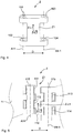
- FIGS. 10 and 11 each an embodiment of the stop device are shown, with these illustrated embodiments of the stop device between the first 11 and a second 12 shift lever act, so that the lines of action W11 or W12 thereof in the maximum extension position, which defines the stop device, at an angle alpha ( ⁇ ) to each other.
- the line of action of the first adjusting lever or of the second adjusting lever 12, 22 is understood in this case to mean the connecting line between the first axis A11, A21 and the third axis A13, A23 or between the third axis A12, A22 and the second axis A12, A22.
- FIG. 10 is a sectional view of an embodiment of a stop device 60 shown on the basis of the first adjustment mechanism 10a, wherein the features of this embodiment may be alternatively or additionally provided on the second adjustment mechanism 10b.
- the stop lever is provided on the adjusting mechanism such that it acts between the first adjusting lever 11 and the second adjusting lever 12.
- a stop lever 16 is arranged on the first adjusting lever 11 in the illustrated embodiment.
- the stop lever 61 is formed integrally with the first lever 11 and as an extension thereof in the direction of the second axis A2.
- the free end 62 of the stop lever 61 is provided for engagement with the upper surface 12a of the second shift lever 12 when the extended position of the high lift flap K is maximum, i. when the high-lift flap K is in its maximum extended position.
- a support device may be provided in particular in the form of a support plate 63.
- a stop lever 16 may be arranged on the second adjusting lever 12.
- the features arise analogously to the embodiment described above, in which the stop lever 16 is arranged on the first adjusting lever 11.
- the stop device 60, 70 with a stop lever 61, 71 to limit the maximum extension position of the high lift flap K be designed such that this between the high lift flap K and the second lever 12, 22 and / or between the main wing H and first adjusting lever 11, 21 acts.
- the stop lever 61, 71 is integrally formed with the second adjusting lever 12, 22 or with a fitting of the high-lift flap K and as an extension thereof in the direction of the fitting of the high-lift flap K or the third joint 13, 23 and the like is designed such that the free end 62, 72 of the stop lever 61, 71 can be brought into a stop position with the fitting of the high-lift flap K or the second adjustment lever 12, 22, to define the maximum extension position of the respective adjustment mechanism 10a, 10b.
- the stop lever 61,71 is integral with the respective first adjusting lever 11, 21 or with a fitting of the main wing H and as an extension thereof in the direction of the fitting of the main wing H or the third joint 13, 23 is formed and the is designed such that the free end 62, 72 of the stop lever 61, 71 in a stop position with the fitting of
- Main wing H or the first lever 11, 21 can be brought to define the maximum extension position of the respective adjustment mechanism 10 a, 10 b.
- the abutment device may be designed such that the abutment device 60, 70 is limited to a maximum extension position of the slat, in which the directions of action W11, W12 of the adjustment levers to each other an angle (alpha) of less than 180 degrees and, for. have a maximum of 179 degrees.
- the stop lever 61 may be provided with a spring device 65, which may be formed in particular as a cross-sectional taper of the stop lever 61.
- a spring device 65 which may be formed in particular as a cross-sectional taper of the stop lever 61.
- the stop of the adjusting lever 11,12 is provided upon reaching the maximum extension position of the adjusting device or the respective adjusting mechanism with a resilient receiving path and minimizes the impact forces. In this way, the maximum occurring forces can be reduced when reaching the stop in the maximum extended position and the structure dimensioning can be optimized.
- the spring device can also be actuated by a spring device 75 (eg, acting between the first adjusting lever or the second adjusting lever) (FIG. FIG. 11 ) be formed as in the in the FIG. 11 illustrated embodiment is provided.
- a spring device 75 eg, acting between the first adjusting lever or the second adjusting lever
- FIG. 11 a Spring device according to the FIG. 11 be arranged in an analogous manner to the main wing 10 or on the high-lift flap K.
- the spring device is arranged and designed such that it exerts a restoring force on the respective adjusting mechanism or the lever of the adjusting mechanism, with which the adjusting mechanism or the lever of the adjusting mechanism are moved to their retracted position. Also, the spring device may be provided and designed such that it performs the function to cushion the achievement of the maximum extension position of the respective adjustment mechanism.
Landscapes
- Engineering & Computer Science (AREA)
- Aviation & Aerospace Engineering (AREA)
- Blinds (AREA)
- Pivots And Pivotal Connections (AREA)
- Transmission Devices (AREA)
- Chairs For Special Purposes, Such As Reclining Chairs (AREA)
- Toys (AREA)
- Handcart (AREA)
Claims (13)
- Aile porteuse (T), dotée d'une aile principale (H), d'un volet hypersustentateur (K), qui au moyen d'au moins deux mécanismes d'ajustage (1, 2) placés côte à côte dans la direction de portée de l'aile porteuse (T) et ajustables au moyen d'un dispositif d'entraînement (50) est placé de manière mobile sur l'aile principale (H), chacun des mécanismes d'ajustage (10) comportant :- un premier levier d'ajustage (11, 21), qui par l'intermédiaire d'une première articulation rotative (13, 23) est articulé sur l'aile principale, en créant un premier axe de rotation (A11, A21),- un deuxième levier d'ajustage (12, 22), qui par l'intermédiaire d'une deuxième articulation rotative (23) est articulé sur le volet hypersustentateur (K) en créant un deuxième axe de rotation (A21, A22),- une troisième articulation (15, 25) qui relie de manière articulée l'un à l'autre le premier (11, 21) et le deuxième (12, 22) leviers d'ajustage, en créant un troisième axe de rotation (A31, A32),
le premier, le deuxième et le troisième axes de rotation (A11, A12, A13 ; A21, A22, A23) s'écoulant à travers un pôle commun (P), qui lors de l'ajustage du volet hypersustentateur (K) est fixe en rapport à la position de l'aile principale,
caractérisée en ce que
sur au moins l'un des mécanismes d'ajustage (1, 2), une pièce d'articulation intermédiaire (Z), pourvue d'un corps de base (Z1) avec au moins un premier logement d'axe et avec un deuxième logement d'axe éloigné dans la direction transversale du corps de base (Z1) est placée et conçue de telle sorte que deux parties d'axe s'écoulant le long de la direction longitudinale (Z-L1) du corps de base (G) soit logées de manière rotative, en étant écartées dans la direction transversale (Z-L2) du corps de base (G),
la pièce d'articulation intermédiaire (Z) logeant de manière rotative- par le premier logement d'axe, en créant le premier axe de rotation (A11, A21), une première partie d'axe et par le deuxième logement d'axe, en créant un quatrième axe de rotation (A4-1), une quatrième partie d'axe, pour l'accouplement du premier levier d'ajustage (11, 21) et de l'aile principale (H) sur la pièce d'articulation intermédiaire (Z) avec un entraxe D entre le premier axe de rotation (A11, A21) et le quatrième axe de rotation (A4-1) ou- par le premier logement d'axe, en créant le deuxième axe de rotation (A12, A22), une deuxième partie d'axe et par le deuxième logement d'axe, en créant un quatrième axe de rotation (A4-2), une quatrième partie d'axe, pour l'accouplement du deuxième levier d'ajustage (12, 22) et du volet hypersustentateur (K) sur la pièce d'articulation intermédiaire (Z) avec un entraxe D entre le deuxième axe de rotation (A12, A22) et le quatrième axe de rotation (A4-2),
le corps de base (Z1)- étant créé d'une seule pièce ou- étant créé en deux pièces à partir de deux leviers intermédiaires (121, 122) s'écoulant chacun dans la direction transversale (Z-L2) du corps de base (Z), le premier levier intermédiaire (121) étant accouplé par l'intermédiaire de deux articulations rotatives (123, 124) sphériques et le deuxième levier intermédiaire (122) étant accouplé par l'intermédiaire d'un palier sphérique (126) et étant accouplé par l'intermédiaire d'un palier non sphérique ou de manière solidaire en rotation. - Aile porteuse (T) selon l'une quelconque des revendications précédentes, caractérisée en ce que la pièce d'articulation intermédiaire (Z) est conçue de telle sorte que le premier axe de rotation (A11, A21) et le quatrième axe de rotation (A4-1) ou le deuxième axe de rotation (A12, A22) et respectivement le quatrième axe de rotation (A4-2) s'écoulent chaque fois à la parallèle l'un de l'autre.
- Aile porteuse (T) selon l'une quelconque des revendications précédentes, caractérisée en ce que la pièce d'articulation intermédiaire (Z) est formée d'un corps de base (Z1) et de deux paires de logements d'axe placées sur celui-ci, avec chacune un premier et un deuxième logements d'axe, chaque fois pour créer un pivot avec un axe, les premiers logements d'axe respectifs recevant de manière rotative une partie d'axe pour créer le premier axe de rotation (A11, A21) ou le deuxième axe de rotation (A12, A22) et les deuxièmes logements d'axe respectifs recevant de manière rotative des parties d'axe pour créer le quatrième axe de rotation (A4-1, A4-2) respectif et le premier et le deuxième logements d'axe de chaque fois une paire de logements d'axe étant écartés l'un de l'autre dans la direction transversale de la pièce d'articulation intermédiaire (Z), pour créer l'entraxe D entre les axes de rotation respectifs.
- Aile porteuse (T) selon la revendication 3, caractérisée en ce que les logements d'axe de la pièce d'articulation intermédiaire (Z) sont placés en décalage mutuel dans la direction longitudinale de celle-ci.
- Aile porteuse (T) selon la revendication 1, caractérisée en ce que le corps de base de la pièce d'articulation intermédiaire (Z, 120) est formé de deux leviers intermédiaires (121, 122) s'étendant le long de la direction transversale : le premier levier intermédiaire (121) comportant une paire de logements d'axe (123a, 124a) avec un premier (123a) et un deuxième logements d'axe (124a), conçus chacun sous la forme d'un palier sphérique, pour loger chacun un tronçon d'axe (123b, 124b), pour accoupler la pièce d'articulation intermédiaire (Z) par une première extrémité (121a) avec le volet hypersustentateur (K) ou avec l'aile principale et par une deuxième extrémité (121b) avec le premier levier d'ajustage (11, 21) ou avec le deuxième levier d'ajustage (12, 22), et le deuxième levier intermédiaire (122) étant assemblé par la première extrémité (122a) de manière solidaire en rotation avec le volet hypersustentateur (K) ou avec l'aile principale (H) et sur la deuxième extrémité (122b) comportant un logement d'axe (126a) conçu sous la forme d'un palier sphérique, par lequel la deuxième extrémité (122b) du deuxième levier intermédiaire (122) est accouplée avec un tronçon d'axe (126b) du premier levier d'ajustage (11, 21) ou du deuxième levier d'ajustage (12, 22).
- Aile porteuse (T) selon la revendication 1, caractérisée en ce que le corps de base (Z1) de la pièce d'articulation intermédiaire (Z, 120) est formé de deux leviers intermédiaires (121, 122) s'étendant le long de la direction transversale (Z-L2) : le premier levier intermédiaire (121) comportant une paire de logements d'axe (123a, 124a) avec un premier et un deuxième logements d'axe, conçus respectivement sous la forme de paliers sphériques, pour loger chacun un tronçon d'axe, pour accoupler la pièce d'articulation intermédiaire (Z) par une première extrémité avec le premier levier d'ajustage (11, 21) ou avec le deuxième levier d'ajustage (12, 22) et par une deuxième extrémité avec le volet hypersustentateur (K) ou avec l'aile principale (H), et le deuxième levier intermédiaire (122) étant assemblé par la première extrémité (122a) de manière solidaire en rotation avec le premier levier d'ajustage (11, 21) ou avec le deuxième levier d'ajustage (12, 22) et sur la deuxième extrémité (122b) comportant un logement d'axe conçu sous la forme d'un palier sphérique, par lequel la deuxième extrémité du deuxième levier intermédiaire est accouplée avec un tronçon d'axe du volet hypersustentateur (K) de l'aile principale (H).
- Aile porteuse (T) selon la revendication 1, caractérisée en ce que le corps de base de la pièce d'articulation intermédiaire (Z, 130) est formé de deux leviers intermédiaires (131, 132) s'étendant le long de la direction transversale : le premier levier intermédiaire (131) comportant des logements d'axe (133a, 134a) écartés l'un de l'autre dans la direction transversale, avec un premier et un deuxième logements d'axe, conçus chacun sous la forme d'un palier sphérique, pour loger chacun de manière rotative un tronçon d'axe (133b, 134b), la pièce d'articulation intermédiaire (Z) étant accouplée par une première extrémité (131a) avec un tronçon d'axe du volet hypersustentateur (K) ou avec un tronçon d'axe de l'aile principale (H) et par une deuxième extrémité (131b) avec un tronçon d'axe (134b) du premier levier d'ajustage (11, 21) ou du deuxième levier d'ajustage (12, 22) et le deuxième levier intermédiaire (132) comportant une paire de logements d'axe (135a, 136a, 137a), écartés l'un de l'autre dans la direction transversale (Z-L2), avec au moins un premier logement d'axe (135a) conçu sous la forme d'un palier sphérique et au moins un deuxième logement d'axe (137a, 138a) conçu sous la forme d'un palier non sphérique, chacun pour recevoir de manière rotative un tronçon d'axe (135b, 136b), la pièce d'articulation intermédiaire (Z) étant accouplée par une première extrémité avec un tronçon d'axe du volet hypersustentateur (K) ou avec un tronçon d'axe de l'aile principale (H) et par une deuxième extrémité avec un tronçon d'axe du premier levier d'ajustage (11, 21) ou du deuxième levier d'ajustage (12, 22).
- Aile porteuse (T) selon la revendication 7, caractérisée en ce que le deuxième levier intermédiaire (132) de la pièce d'articulation intermédiaire (Z) comporte des logements d'axe écartés les uns des autres dans la direction transversale, avec un premier logement d'axe (135a) et deux deuxièmes logements d'axe (137a, 138a), qui sont conçus chacun sous la forme d'un palier non sphérique et pour loger de manière rotative un tronçon d'axe (136b), la pièce d'articulation intermédiaire (Z) étant accouplée par une première extrémité avec un tronçon d'axe du volet hypersustentateur (K) ou avec un tronçon d'axe de l'aile principale (H) et par une deuxième extrémité avec un tronçon d'axe du premier levier d'ajustage (11, 21) ou du deuxième levier d'ajustage (12, 22).
- Aile porteuse (T) selon la revendication 7, caractérisée en ce que le deuxième levier intermédiaire (132) de la pièce d'articulation intermédiaire (Z) comporte des logements d'axes écartés les uns des autres dans la direction transversale, avec deux premiers logements d'axe et un deuxième logement d'axe, qui sont conçus chacun sous la forme de paliers non sphériques et pour loger de manière rotative un tronçon d'axe, la pièce d'articulation intermédiaire (Z) étant accouplée par une première extrémité avec un tronçon d'axe du volet hypersustentateur (K) ou avec un tronçon d'axe de l'aile principale (H) et par une deuxième extrémité avec un tronçon d'axe du premier levier d'ajustage (11, 21) ou du deuxième levier d'ajustage (12, 22).
- Aile porteuse (T) selon l'une quelconque des revendications précédentes, caractérisée en ce que le volet hypersustentateur est un volet de bord d'attaque ou un slat.
- Aile porteuse (T) selon l'une quelconque des revendications précédentes, caractérisée en ce que le volet hypersustentateur est un volet de bord de fuite.
- Aile porteuse (T) selon l'une quelconque des revendications précédentes, caractérisée en ce que l'aile porteuse (T) comporte un dispositif de butée (60, 70) destiné à limiter la position de déploiement maximal du volet hypersustentateur (K) et en ce que le dispositif de butée (60, 70) est formé d'un levier de butée (61, 71) agissant entre le premier (11, 21) et le deuxième (12, 22) leviers d'ajustage, qui est formé d'une seule pièce avec le premier levier d'ajustage (11,21) ou avec le deuxième levier d'ajustage (12, 22) et en tant que prolongement de celui-dans la direction du deuxième axe (A12, A22) ou du premier axe (A11, A21) et qui est conçu de telle sorte que l'extrémité libre du levier de butée (61, 71) puisse être amenée dans une position de butée avec un dispositif d'appui (63, 73) sur le deuxième levier d'ajustage (12, 22) ou sur le premier levier d'ajustage (11, 21), pour définir la position de déploiement maximal du mécanisme d'ajustage (10a, 10b) respectif.
- Aile porteuse (T) selon l'une quelconque des revendications précédentes, caractérisée en ce que l'aile porteuse (T) comporte un dispositif de butée (60, 70) destiné à limiter la position de déploiement maximal du volet hypersustentateur (K) et en ce que le dispositif de butée (60, 70) est formé avec un levier de butée (61, 71) pour limiter la position de déploiement maximal du volet hypersustentateur (K), qui est formé d'une seule pièce avec le premier levier d'ajustage (11, 21) ou avec une ferrure de l'aile principale (H) et en tant que prolongement de celui (celle)-ci dans la direction de la ferrure de l'aile principale (H) ou de la troisième articulation (13, 23) et qui est conçu de telle sorte que l'extrémité libre (62, 72) du levier de butée (61, 71) puisse être amenée dans une position de butée avec la ferrure de l'aile principale (H) ou avec le premier levier d'ajustage (11, 21), pour définir la position de déploiement maximal du mécanisme d'ajustage (10a, 10b) respectif.
Applications Claiming Priority (3)
| Application Number | Priority Date | Filing Date | Title |
|---|---|---|---|
| US16414709P | 2009-03-27 | 2009-03-27 | |
| DE102009015330A DE102009015330A1 (de) | 2009-03-27 | 2009-03-27 | Tragflügel mit einer Hochauftriebsklappe |
| PCT/EP2010/001984 WO2010108699A1 (fr) | 2009-03-27 | 2010-03-29 | Surface portante à volet hypersustentateur |
Publications (2)
| Publication Number | Publication Date |
|---|---|
| EP2411269A1 EP2411269A1 (fr) | 2012-02-01 |
| EP2411269B1 true EP2411269B1 (fr) | 2019-07-24 |
Family
ID=42664097
Family Applications (1)
| Application Number | Title | Priority Date | Filing Date |
|---|---|---|---|
| EP10711352.4A Active EP2411269B1 (fr) | 2009-03-27 | 2010-03-29 | Surface portante à volet hypersustentateur |
Country Status (7)
| Country | Link |
|---|---|
| US (1) | US8967550B2 (fr) |
| EP (1) | EP2411269B1 (fr) |
| CN (1) | CN102365203B (fr) |
| CA (1) | CA2757225A1 (fr) |
| DE (1) | DE102009015330A1 (fr) |
| RU (1) | RU2011143225A (fr) |
| WO (1) | WO2010108699A1 (fr) |
Families Citing this family (7)
| Publication number | Priority date | Publication date | Assignee | Title |
|---|---|---|---|---|
| DE102011105912A1 (de) | 2011-06-28 | 2013-01-03 | Airbus Operations Gmbh | Tragflügel mit einem Hauptflügel und einem Hochauftriebskörper sowie Verfahren zur Ausführung von Verstellbewegungen eines Hochauftriebskörpers gegenüber einem Hauptflügel |
| GB201222308D0 (en) * | 2012-12-11 | 2013-01-23 | Airbus Operations Ltd | Support assembly |
| US12589869B2 (en) | 2021-02-19 | 2026-03-31 | Archer Aviation Inc. | Aircraft |
| EP3998207A1 (fr) * | 2021-02-19 | 2022-05-18 | Lilium eAircraft GmbH | Aéronef |
| EP4112450A1 (fr) | 2021-06-30 | 2023-01-04 | Airbus Operations GmbH | Aile d'aéronef |
| CN114455067B (zh) * | 2021-11-23 | 2024-02-09 | 北京航空航天大学 | 一种适用于超长襟翼的增升装置 |
| US12024289B2 (en) * | 2022-08-23 | 2024-07-02 | Gulfstream Aerospace Corporation | Reduced-friction roller and related assembly for a moveable control surface of an aircraft |
Family Cites Families (9)
| Publication number | Priority date | Publication date | Assignee | Title |
|---|---|---|---|---|
| US2973925A (en) * | 1958-03-24 | 1961-03-07 | Lockheed Aircraft Corp | Aerodynamically automatic airfoil slat mechanism |
| US5681013A (en) * | 1995-12-26 | 1997-10-28 | The Boeing Company | Vortex leading edge flap assembly for supersonic airplanes |
| US6851255B2 (en) * | 2002-12-18 | 2005-02-08 | Pratt & Whitney Canada Corp. | Normally open reverse flow flapper valve |
| GB0314000D0 (en) * | 2003-06-17 | 2003-07-23 | Broadbent Michael C | Direct rotate swing slat system |
| DE10328717B3 (de) * | 2003-06-25 | 2004-12-02 | Eads Deutschland Gmbh | Betätigungseinrichtung für eine an der Hinterkante des Tragflügels eines Flugzeugs angeordnete Ruderklappe |
| DE102005016638B4 (de) * | 2005-04-11 | 2010-12-30 | Eads Deutschland Gmbh | Flügelklappen-Mechanismus zur Verstellung einer einem Tragflügel zugeordneten aerodynamischen Flügelklappe |
| DE102005031840B4 (de) * | 2005-07-06 | 2013-11-14 | Airbus Operations Gmbh | Antriebs- und Führungsvorrichtung für eine an einem Flugzeugtragflügel angeordnete Klappe |
| DE102005044549B4 (de) * | 2005-09-17 | 2008-04-17 | Eads Deutschland Gmbh | Flugzeugflügel mit ausfahrbarer Nasenklappe |
| DE102006036464B4 (de) * | 2006-08-04 | 2009-08-20 | Airbus Deutschland Gmbh | Hochauftriebssystem für ein Flugzeug |
-
2009
- 2009-03-27 DE DE102009015330A patent/DE102009015330A1/de not_active Withdrawn
-
2010
- 2010-03-29 WO PCT/EP2010/001984 patent/WO2010108699A1/fr not_active Ceased
- 2010-03-29 RU RU2011143225/11A patent/RU2011143225A/ru not_active Application Discontinuation
- 2010-03-29 CA CA2757225A patent/CA2757225A1/fr not_active Abandoned
- 2010-03-29 EP EP10711352.4A patent/EP2411269B1/fr active Active
- 2010-03-29 US US13/255,276 patent/US8967550B2/en active Active
- 2010-03-29 CN CN201080014156.5A patent/CN102365203B/zh not_active Expired - Fee Related
Non-Patent Citations (1)
| Title |
|---|
| None * |
Also Published As
| Publication number | Publication date |
|---|---|
| CN102365203A (zh) | 2012-02-29 |
| CN102365203B (zh) | 2015-04-01 |
| US20120061524A1 (en) | 2012-03-15 |
| RU2011143225A (ru) | 2013-05-10 |
| US8967550B2 (en) | 2015-03-03 |
| WO2010108699A1 (fr) | 2010-09-30 |
| EP2411269A1 (fr) | 2012-02-01 |
| DE102009015330A1 (de) | 2010-09-30 |
| CA2757225A1 (fr) | 2010-09-30 |
Similar Documents
| Publication | Publication Date | Title |
|---|---|---|
| EP2411269B1 (fr) | Surface portante à volet hypersustentateur | |
| DE102007049864B4 (de) | Sitzgestell eines Kraftfahrzeugsitzes mit einem Sitzträger, der zwei Seitenteile hat | |
| DE102009006387B4 (de) | Vorrichtung zur elektrischen Einstellung eines Fahrzeugsitzes | |
| DE60002808T2 (de) | Propellerrotornabe | |
| EP2089272B1 (fr) | Assemblage aile-fuselage d'un avion | |
| EP2467297B1 (fr) | Mécanisme de réglage d'un dispositif de réglage servant à accoupler un volet de réglage à une aile principale et dispositif de réglage associé | |
| DE3013774C2 (fr) | ||
| EP2280867B1 (fr) | Dispositif de couplage latéral pour maintenir et guider au moins un corps aérodynamique par rapport à une aile principale d'un aéronef, voilure et aéronef comprenant ledit dispositif | |
| DE602005000760T2 (de) | Falttür für Flugzeugfahrwerk | |
| DE102011082888A1 (de) | Auftriebsklappenlagervorrichtung, Auftriebsklappenanordnung, Tragflügel sowie Flugzeug | |
| EP2238023B1 (fr) | Système hypersustentateur pour un avion | |
| DE102015201232A1 (de) | Fahrzeugsitz | |
| EP2707250B1 (fr) | Siège de véhicule, en particulier siège de véhicule automobile | |
| DE2142975C3 (de) | Abstützung des Wagenkastens auf dem Drehgestell eines Schienenfahrzeugs | |
| EP2411268B1 (fr) | Surface portante à volet hypersustentateur | |
| EP1836070B1 (fr) | Siege de vehicule | |
| EP3287305B1 (fr) | Structure articulee et passage comprenant une structure articulee | |
| EP1613534B1 (fr) | Rotor et giravion equipe d'un rotor de ce type | |
| EP2357121A2 (fr) | Dispositif d'aileron doté d'un mécanisme de compensation de tolérances | |
| EP2883787B1 (fr) | Mécanisme d'entraînement pour une structure de bord d'attaque déformable d'une aile | |
| EP1762489B1 (fr) | Système de siège pour aéronefs | |
| DE2827320A1 (de) | Rotor eines drehfluegelflugzeugs | |
| AT12684U1 (de) | Laufwagen für einen schiebeflügel | |
| WO2002047976A2 (fr) | Aile aerodynamique a courbure au moins partiellement variable et articulation structurelle | |
| DE102023130056A1 (de) | Aufhängungssystem mit zweistufigem torsionsstab |
Legal Events
| Date | Code | Title | Description |
|---|---|---|---|
| PUAI | Public reference made under article 153(3) epc to a published international application that has entered the european phase |
Free format text: ORIGINAL CODE: 0009012 |
|
| 17P | Request for examination filed |
Effective date: 20111026 |
|
| AK | Designated contracting states |
Kind code of ref document: A1 Designated state(s): AT BE BG CH CY CZ DE DK EE ES FI FR GB GR HR HU IE IS IT LI LT LU LV MC MK MT NL NO PL PT RO SE SI SK SM TR |
|
| DAX | Request for extension of the european patent (deleted) | ||
| 17Q | First examination report despatched |
Effective date: 20130819 |
|
| STAA | Information on the status of an ep patent application or granted ep patent |
Free format text: STATUS: EXAMINATION IS IN PROGRESS |
|
| RIC1 | Information provided on ipc code assigned before grant |
Ipc: B64C 9/22 20060101AFI20170731BHEP Ipc: B64C 9/16 20060101ALI20170731BHEP Ipc: B64C 9/02 20060101ALI20170731BHEP |
|
| GRAP | Despatch of communication of intention to grant a patent |
Free format text: ORIGINAL CODE: EPIDOSNIGR1 |
|
| STAA | Information on the status of an ep patent application or granted ep patent |
Free format text: STATUS: GRANT OF PATENT IS INTENDED |
|
| INTG | Intention to grant announced |
Effective date: 20171020 |
|
| GRAS | Grant fee paid |
Free format text: ORIGINAL CODE: EPIDOSNIGR3 |
|
| GRAA | (expected) grant |
Free format text: ORIGINAL CODE: 0009210 |
|
| STAA | Information on the status of an ep patent application or granted ep patent |
Free format text: STATUS: THE PATENT HAS BEEN GRANTED |
|
| AK | Designated contracting states |
Kind code of ref document: B1 Designated state(s): AT BE BG CH CY CZ DE DK EE ES FI FR GB GR HR HU IE IS IT LI LT LU LV MC MK MT NL NO PL PT RO SE SI SK SM TR |
|
| REG | Reference to a national code |
Ref country code: GB Ref legal event code: FG4D Free format text: NOT ENGLISH |
|
| REG | Reference to a national code |
Ref country code: CH Ref legal event code: EP |
|
| REG | Reference to a national code |
Ref country code: DE Ref legal event code: R096 Ref document number: 502010016147 Country of ref document: DE |
|
| REG | Reference to a national code |
Ref country code: AT Ref legal event code: REF Ref document number: 1157859 Country of ref document: AT Kind code of ref document: T Effective date: 20190815 |
|
| REG | Reference to a national code |
Ref country code: IE Ref legal event code: FG4D Free format text: LANGUAGE OF EP DOCUMENT: GERMAN |
|
| REG | Reference to a national code |
Ref country code: NL Ref legal event code: MP Effective date: 20190724 |
|
| REG | Reference to a national code |
Ref country code: LT Ref legal event code: MG4D |
|
| PG25 | Lapsed in a contracting state [announced via postgrant information from national office to epo] |
Ref country code: LT Free format text: LAPSE BECAUSE OF FAILURE TO SUBMIT A TRANSLATION OF THE DESCRIPTION OR TO PAY THE FEE WITHIN THE PRESCRIBED TIME-LIMIT Effective date: 20190724 Ref country code: HR Free format text: LAPSE BECAUSE OF FAILURE TO SUBMIT A TRANSLATION OF THE DESCRIPTION OR TO PAY THE FEE WITHIN THE PRESCRIBED TIME-LIMIT Effective date: 20190724 Ref country code: NO Free format text: LAPSE BECAUSE OF FAILURE TO SUBMIT A TRANSLATION OF THE DESCRIPTION OR TO PAY THE FEE WITHIN THE PRESCRIBED TIME-LIMIT Effective date: 20191024 Ref country code: NL Free format text: LAPSE BECAUSE OF FAILURE TO SUBMIT A TRANSLATION OF THE DESCRIPTION OR TO PAY THE FEE WITHIN THE PRESCRIBED TIME-LIMIT Effective date: 20190724 Ref country code: PT Free format text: LAPSE BECAUSE OF FAILURE TO SUBMIT A TRANSLATION OF THE DESCRIPTION OR TO PAY THE FEE WITHIN THE PRESCRIBED TIME-LIMIT Effective date: 20191125 Ref country code: BG Free format text: LAPSE BECAUSE OF FAILURE TO SUBMIT A TRANSLATION OF THE DESCRIPTION OR TO PAY THE FEE WITHIN THE PRESCRIBED TIME-LIMIT Effective date: 20191024 Ref country code: FI Free format text: LAPSE BECAUSE OF FAILURE TO SUBMIT A TRANSLATION OF THE DESCRIPTION OR TO PAY THE FEE WITHIN THE PRESCRIBED TIME-LIMIT Effective date: 20190724 Ref country code: SE Free format text: LAPSE BECAUSE OF FAILURE TO SUBMIT A TRANSLATION OF THE DESCRIPTION OR TO PAY THE FEE WITHIN THE PRESCRIBED TIME-LIMIT Effective date: 20190724 |
|
| PG25 | Lapsed in a contracting state [announced via postgrant information from national office to epo] |
Ref country code: LV Free format text: LAPSE BECAUSE OF FAILURE TO SUBMIT A TRANSLATION OF THE DESCRIPTION OR TO PAY THE FEE WITHIN THE PRESCRIBED TIME-LIMIT Effective date: 20190724 Ref country code: GR Free format text: LAPSE BECAUSE OF FAILURE TO SUBMIT A TRANSLATION OF THE DESCRIPTION OR TO PAY THE FEE WITHIN THE PRESCRIBED TIME-LIMIT Effective date: 20191025 Ref country code: IS Free format text: LAPSE BECAUSE OF FAILURE TO SUBMIT A TRANSLATION OF THE DESCRIPTION OR TO PAY THE FEE WITHIN THE PRESCRIBED TIME-LIMIT Effective date: 20191124 Ref country code: ES Free format text: LAPSE BECAUSE OF FAILURE TO SUBMIT A TRANSLATION OF THE DESCRIPTION OR TO PAY THE FEE WITHIN THE PRESCRIBED TIME-LIMIT Effective date: 20190724 |
|
| PG25 | Lapsed in a contracting state [announced via postgrant information from national office to epo] |
Ref country code: TR Free format text: LAPSE BECAUSE OF FAILURE TO SUBMIT A TRANSLATION OF THE DESCRIPTION OR TO PAY THE FEE WITHIN THE PRESCRIBED TIME-LIMIT Effective date: 20190724 |
|
| PG25 | Lapsed in a contracting state [announced via postgrant information from national office to epo] |
Ref country code: EE Free format text: LAPSE BECAUSE OF FAILURE TO SUBMIT A TRANSLATION OF THE DESCRIPTION OR TO PAY THE FEE WITHIN THE PRESCRIBED TIME-LIMIT Effective date: 20190724 Ref country code: DK Free format text: LAPSE BECAUSE OF FAILURE TO SUBMIT A TRANSLATION OF THE DESCRIPTION OR TO PAY THE FEE WITHIN THE PRESCRIBED TIME-LIMIT Effective date: 20190724 Ref country code: IT Free format text: LAPSE BECAUSE OF FAILURE TO SUBMIT A TRANSLATION OF THE DESCRIPTION OR TO PAY THE FEE WITHIN THE PRESCRIBED TIME-LIMIT Effective date: 20190724 Ref country code: RO Free format text: LAPSE BECAUSE OF FAILURE TO SUBMIT A TRANSLATION OF THE DESCRIPTION OR TO PAY THE FEE WITHIN THE PRESCRIBED TIME-LIMIT Effective date: 20190724 Ref country code: PL Free format text: LAPSE BECAUSE OF FAILURE TO SUBMIT A TRANSLATION OF THE DESCRIPTION OR TO PAY THE FEE WITHIN THE PRESCRIBED TIME-LIMIT Effective date: 20190724 |
|
| PGFP | Annual fee paid to national office [announced via postgrant information from national office to epo] |
Ref country code: DE Payment date: 20200320 Year of fee payment: 11 Ref country code: GB Payment date: 20200323 Year of fee payment: 11 |
|
| PG25 | Lapsed in a contracting state [announced via postgrant information from national office to epo] |
Ref country code: IS Free format text: LAPSE BECAUSE OF FAILURE TO SUBMIT A TRANSLATION OF THE DESCRIPTION OR TO PAY THE FEE WITHIN THE PRESCRIBED TIME-LIMIT Effective date: 20200224 Ref country code: SK Free format text: LAPSE BECAUSE OF FAILURE TO SUBMIT A TRANSLATION OF THE DESCRIPTION OR TO PAY THE FEE WITHIN THE PRESCRIBED TIME-LIMIT Effective date: 20190724 Ref country code: CZ Free format text: LAPSE BECAUSE OF FAILURE TO SUBMIT A TRANSLATION OF THE DESCRIPTION OR TO PAY THE FEE WITHIN THE PRESCRIBED TIME-LIMIT Effective date: 20190724 Ref country code: SM Free format text: LAPSE BECAUSE OF FAILURE TO SUBMIT A TRANSLATION OF THE DESCRIPTION OR TO PAY THE FEE WITHIN THE PRESCRIBED TIME-LIMIT Effective date: 20190724 |
|
| REG | Reference to a national code |
Ref country code: DE Ref legal event code: R097 Ref document number: 502010016147 Country of ref document: DE |
|
| PLBE | No opposition filed within time limit |
Free format text: ORIGINAL CODE: 0009261 |
|
| STAA | Information on the status of an ep patent application or granted ep patent |
Free format text: STATUS: NO OPPOSITION FILED WITHIN TIME LIMIT |
|
| PG2D | Information on lapse in contracting state deleted |
Ref country code: IS |
|
| 26N | No opposition filed |
Effective date: 20200603 |
|
| PG25 | Lapsed in a contracting state [announced via postgrant information from national office to epo] |
Ref country code: SI Free format text: LAPSE BECAUSE OF FAILURE TO SUBMIT A TRANSLATION OF THE DESCRIPTION OR TO PAY THE FEE WITHIN THE PRESCRIBED TIME-LIMIT Effective date: 20190724 |
|
| PG25 | Lapsed in a contracting state [announced via postgrant information from national office to epo] |
Ref country code: MC Free format text: LAPSE BECAUSE OF FAILURE TO SUBMIT A TRANSLATION OF THE DESCRIPTION OR TO PAY THE FEE WITHIN THE PRESCRIBED TIME-LIMIT Effective date: 20190724 |
|
| REG | Reference to a national code |
Ref country code: CH Ref legal event code: PL |
|
| REG | Reference to a national code |
Ref country code: BE Ref legal event code: MM Effective date: 20200331 |
|
| PG25 | Lapsed in a contracting state [announced via postgrant information from national office to epo] |
Ref country code: LU Free format text: LAPSE BECAUSE OF NON-PAYMENT OF DUE FEES Effective date: 20200329 |
|
| PG25 | Lapsed in a contracting state [announced via postgrant information from national office to epo] |
Ref country code: FR Free format text: LAPSE BECAUSE OF NON-PAYMENT OF DUE FEES Effective date: 20200331 Ref country code: CH Free format text: LAPSE BECAUSE OF NON-PAYMENT OF DUE FEES Effective date: 20200331 Ref country code: LI Free format text: LAPSE BECAUSE OF NON-PAYMENT OF DUE FEES Effective date: 20200331 Ref country code: IE Free format text: LAPSE BECAUSE OF NON-PAYMENT OF DUE FEES Effective date: 20200329 |
|
| PG25 | Lapsed in a contracting state [announced via postgrant information from national office to epo] |
Ref country code: BE Free format text: LAPSE BECAUSE OF NON-PAYMENT OF DUE FEES Effective date: 20200331 |
|
| REG | Reference to a national code |
Ref country code: AT Ref legal event code: MM01 Ref document number: 1157859 Country of ref document: AT Kind code of ref document: T Effective date: 20200329 |
|
| PG25 | Lapsed in a contracting state [announced via postgrant information from national office to epo] |
Ref country code: AT Free format text: LAPSE BECAUSE OF NON-PAYMENT OF DUE FEES Effective date: 20200329 |
|
| REG | Reference to a national code |
Ref country code: DE Ref legal event code: R119 Ref document number: 502010016147 Country of ref document: DE |
|
| GBPC | Gb: european patent ceased through non-payment of renewal fee |
Effective date: 20210329 |
|
| PG25 | Lapsed in a contracting state [announced via postgrant information from national office to epo] |
Ref country code: DE Free format text: LAPSE BECAUSE OF NON-PAYMENT OF DUE FEES Effective date: 20211001 Ref country code: GB Free format text: LAPSE BECAUSE OF NON-PAYMENT OF DUE FEES Effective date: 20210329 |
|
| PG25 | Lapsed in a contracting state [announced via postgrant information from national office to epo] |
Ref country code: MT Free format text: LAPSE BECAUSE OF FAILURE TO SUBMIT A TRANSLATION OF THE DESCRIPTION OR TO PAY THE FEE WITHIN THE PRESCRIBED TIME-LIMIT Effective date: 20190724 Ref country code: CY Free format text: LAPSE BECAUSE OF FAILURE TO SUBMIT A TRANSLATION OF THE DESCRIPTION OR TO PAY THE FEE WITHIN THE PRESCRIBED TIME-LIMIT Effective date: 20190724 |
|
| PG25 | Lapsed in a contracting state [announced via postgrant information from national office to epo] |
Ref country code: MK Free format text: LAPSE BECAUSE OF FAILURE TO SUBMIT A TRANSLATION OF THE DESCRIPTION OR TO PAY THE FEE WITHIN THE PRESCRIBED TIME-LIMIT Effective date: 20190724 |