EP2411270B1 - Düsenloser fan für turbomaschine mit schaufeln mit einstellbarem winkel - Google Patents
Düsenloser fan für turbomaschine mit schaufeln mit einstellbarem winkel Download PDFInfo
- Publication number
- EP2411270B1 EP2411270B1 EP10708250.5A EP10708250A EP2411270B1 EP 2411270 B1 EP2411270 B1 EP 2411270B1 EP 10708250 A EP10708250 A EP 10708250A EP 2411270 B1 EP2411270 B1 EP 2411270B1
- Authority
- EP
- European Patent Office
- Prior art keywords
- ring
- plate
- recess
- sectors
- annular
- Prior art date
- Legal status (The legal status is an assumption and is not a legal conclusion. Google has not performed a legal analysis and makes no representation as to the accuracy of the status listed.)
- Active
Links
Images


Classifications
-
- B—PERFORMING OPERATIONS; TRANSPORTING
- B64—AIRCRAFT; AVIATION; COSMONAUTICS
- B64C—AEROPLANES; HELICOPTERS
- B64C11/00—Propellers, e.g. of ducted type; Features common to propellers and rotors for rotorcraft
- B64C11/02—Hub construction
- B64C11/04—Blade mountings
- B64C11/06—Blade mountings for variable-pitch blades
-
- B—PERFORMING OPERATIONS; TRANSPORTING
- B64—AIRCRAFT; AVIATION; COSMONAUTICS
- B64C—AEROPLANES; HELICOPTERS
- B64C11/00—Propellers, e.g. of ducted type; Features common to propellers and rotors for rotorcraft
- B64C11/46—Arrangements of, or constructional features peculiar to, multiple propellers
- B64C11/48—Units of two or more coaxial propellers
-
- F—MECHANICAL ENGINEERING; LIGHTING; HEATING; WEAPONS; BLASTING
- F16—ENGINEERING ELEMENTS AND UNITS; GENERAL MEASURES FOR PRODUCING AND MAINTAINING EFFECTIVE FUNCTIONING OF MACHINES OR INSTALLATIONS; THERMAL INSULATION IN GENERAL
- F16C—SHAFTS; FLEXIBLE SHAFTS; ELEMENTS OR CRANKSHAFT MECHANISMS; ROTARY BODIES OTHER THAN GEARING ELEMENTS; BEARINGS
- F16C19/00—Bearings with rolling contact, for exclusively rotary movement
- F16C19/02—Bearings with rolling contact, for exclusively rotary movement with bearing balls essentially of the same size in one or more circular rows
- F16C19/14—Bearings with rolling contact, for exclusively rotary movement with bearing balls essentially of the same size in one or more circular rows for both radial and axial load
- F16C19/16—Bearings with rolling contact, for exclusively rotary movement with bearing balls essentially of the same size in one or more circular rows for both radial and axial load with a single row of balls
- F16C19/163—Bearings with rolling contact, for exclusively rotary movement with bearing balls essentially of the same size in one or more circular rows for both radial and axial load with a single row of balls with angular contact
-
- F—MECHANICAL ENGINEERING; LIGHTING; HEATING; WEAPONS; BLASTING
- F16—ENGINEERING ELEMENTS AND UNITS; GENERAL MEASURES FOR PRODUCING AND MAINTAINING EFFECTIVE FUNCTIONING OF MACHINES OR INSTALLATIONS; THERMAL INSULATION IN GENERAL
- F16C—SHAFTS; FLEXIBLE SHAFTS; ELEMENTS OR CRANKSHAFT MECHANISMS; ROTARY BODIES OTHER THAN GEARING ELEMENTS; BEARINGS
- F16C23/00—Bearings for exclusively rotary movement adjustable for aligning or positioning
- F16C23/06—Ball or roller bearings
-
- F—MECHANICAL ENGINEERING; LIGHTING; HEATING; WEAPONS; BLASTING
- F16—ENGINEERING ELEMENTS AND UNITS; GENERAL MEASURES FOR PRODUCING AND MAINTAINING EFFECTIVE FUNCTIONING OF MACHINES OR INSTALLATIONS; THERMAL INSULATION IN GENERAL
- F16C—SHAFTS; FLEXIBLE SHAFTS; ELEMENTS OR CRANKSHAFT MECHANISMS; ROTARY BODIES OTHER THAN GEARING ELEMENTS; BEARINGS
- F16C35/00—Rigid support of bearing units; Housings, e.g. caps, covers
- F16C35/04—Rigid support of bearing units; Housings, e.g. caps, covers in the case of ball or roller bearings
- F16C35/06—Mounting or dismounting of ball or roller bearings; Fixing them onto shaft or in housing
- F16C35/07—Fixing them on the shaft or housing with interposition of an element
- F16C35/073—Fixing them on the shaft or housing with interposition of an element between shaft and inner race ring
-
- B—PERFORMING OPERATIONS; TRANSPORTING
- B64—AIRCRAFT; AVIATION; COSMONAUTICS
- B64D—EQUIPMENT FOR FITTING IN OR TO AIRCRAFT; FLIGHT SUITS; PARACHUTES; ARRANGEMENT OR MOUNTING OF POWER PLANTS OR PROPULSION TRANSMISSIONS IN AIRCRAFT
- B64D27/00—Arrangement or mounting of power plants in aircraft; Aircraft characterised by the type or position of power plants
- B64D27/02—Aircraft characterised by the type or position of power plants
- B64D27/026—Aircraft characterised by the type or position of power plants comprising different types of power plants, e.g. combination of a piston engine and a gas-turbine
-
- F—MECHANICAL ENGINEERING; LIGHTING; HEATING; WEAPONS; BLASTING
- F16—ENGINEERING ELEMENTS AND UNITS; GENERAL MEASURES FOR PRODUCING AND MAINTAINING EFFECTIVE FUNCTIONING OF MACHINES OR INSTALLATIONS; THERMAL INSULATION IN GENERAL
- F16C—SHAFTS; FLEXIBLE SHAFTS; ELEMENTS OR CRANKSHAFT MECHANISMS; ROTARY BODIES OTHER THAN GEARING ELEMENTS; BEARINGS
- F16C2326/00—Articles relating to transporting
- F16C2326/43—Aeroplanes; Helicopters
-
- F—MECHANICAL ENGINEERING; LIGHTING; HEATING; WEAPONS; BLASTING
- F16—ENGINEERING ELEMENTS AND UNITS; GENERAL MEASURES FOR PRODUCING AND MAINTAINING EFFECTIVE FUNCTIONING OF MACHINES OR INSTALLATIONS; THERMAL INSULATION IN GENERAL
- F16C—SHAFTS; FLEXIBLE SHAFTS; ELEMENTS OR CRANKSHAFT MECHANISMS; ROTARY BODIES OTHER THAN GEARING ELEMENTS; BEARINGS
- F16C2360/00—Engines or pumps
- F16C2360/23—Gas turbine engines
-
- Y—GENERAL TAGGING OF NEW TECHNOLOGICAL DEVELOPMENTS; GENERAL TAGGING OF CROSS-SECTIONAL TECHNOLOGIES SPANNING OVER SEVERAL SECTIONS OF THE IPC; TECHNICAL SUBJECTS COVERED BY FORMER USPC CROSS-REFERENCE ART COLLECTIONS [XRACs] AND DIGESTS
- Y02—TECHNOLOGIES OR APPLICATIONS FOR MITIGATION OR ADAPTATION AGAINST CLIMATE CHANGE
- Y02T—CLIMATE CHANGE MITIGATION TECHNOLOGIES RELATED TO TRANSPORTATION
- Y02T50/00—Aeronautics or air transport
- Y02T50/60—Efficient propulsion technologies, e.g. for aircraft
Definitions
- the present invention relates to a propeller with variable pitch blades for a turbomachine type unfired propellers (English “open rotor” or “unducted fan”).
- a turbomachine of this type comprises two coaxial and contra-rotating external propellers, respectively upstream and downstream, which are each driven in rotation by a turbine of the turbomachine and which extend substantially radially outside the nacelle of this turbomachine.
- Each helix comprises a polygonal rotor element comprising substantially radial cylindrical housings distributed around the longitudinal axis of the turbomachine and in which are mounted support plates of the blades of the propeller.
- Each blade comprises for example a dovetailed section foot which is engaged in a groove of complementary shape of the plate.
- each plate comprises a substantially cylindrical body screwed into a cylindrical ring which is centered and guided in rotation in a housing of the rotor element by means of roller stops.
- the plates and the rings can rotate in the housings of the rotor element and are rotated about the axes of the blades by appropriate means so as to adjust the angular setting of the blades, and to optimize it according to the conditions of the rotor. operation of the turbomachine.
- the blades of the propeller are subjected to very large centrifugal forces of up to 30,000 daN, these forces being transmitted to the rotor element by means of plates, rings and roller stops and passing through the screw threads of the plates in the crowns.
- These nets are not usually designed for transmit such forces and may deteriorate rapidly, limiting the life of the propeller.
- the invention aims in particular to provide a simple, effective and economical solution to this problem.
- the blades of the propeller are rotatably mounted about their axes in radial housings of an annular rotor element and each blade being carried by a cylindrical body plate which is engaged from the outside in a radial housing of the rotor element and which is retained by an annular ring mounted from the inside in the housing and applied to an inner rim of the housing via a bearing.
- the ring is sectorized and comprises a radially inner portion fitted by fitting the ring sectors in an annular groove of the outer surface of the body of the plate.
- each blade support plate is retained in a housing of the rotor element by a sectorized ring which is nested in an annular groove of the body of the plate and which is applied to an inner rim of the housing of the element.
- rotor by means of a bearing, so that the centrifugal forces applied to the blade in operation are taken up by the part of the ring gear fitted in the groove of the plate and transmitted by the bearing to the rotor element. This makes it possible to significantly increase the life of the propeller.
- the sectorized ring is formed of two, three, or four crown sectors, or more, which are nested on the body of the turntable as follows.
- the body of the plate is engaged in the housing of the rotor element from the outside, by displacement of the plate in translation along the axis of the housing.
- Each ring sector is engaged in the housing from the inside, between the body of the plate and a cylindrical internal surface of the housing, by translation along the axis of the housing, until it is located at the of the annular groove of the body of the plate.
- Each sector is then moved in radial translation (relative to the axis of the housing) from outside to inside so that its inner portion fits into the outer groove of the body of the plate.
- the crown is then retained radially on the plate by pressing the flanks of its inner portion on the inner side walls of the groove of the plate.
- the aforementioned inner part of the ring may be formed by an inner annular flange.
- the ring may comprise two sectors each having an angular extent of about 180 °, or three sectors each having an angular extent of about 120 °, or four sectors each having an angular extent of about 90 °.
- the annular portion of the ring is advantageously engaged in the annular groove of the body of the plate with an adjustment with very low tolerance of assembly.
- the ring sectors are also blocked in the groove of the body of the plate by locking means fixed on the body of the plate from inside the housing.
- the ring comprises a frustoconical outer surface widening outwards and on which is applied a frustoconical inner surface substantially complementary to a ring which is engaged from the inside in the housing and which is biased on the ring by a nut screwed on the body of the plate.
- the nut keeps the ring resting on the frustoconical surface of the crown which is thus pushed towards the bottom of the groove of the body of the plate. This nut is only used to support and maintaining in position the ring, and is therefore not biased for transmitting the forces transmitted by the blade in operation.
- a locking washer can be inserted between the ring and the nut, this washer comprising first means cooperating by shape bonding with complementary means of the body of the plate, and second means cooperating by bonding forms with complementary means the nut, to immobilize in rotation the nut vis-à-vis the plate.
- the ring comprises an outer frustoconical surface widening outwards and on which is applied a frustoconical inner surface substantially complementary to a ring which comprises an internal screw thread on the body of the plate.
- the ring comprises a cylindrical rim which extends axially inwardly with respect to the axis of the housing and which is applied to an outer cylindrical surface of the body of the plate.
- the ring then has a substantially L-shaped section, one branch is formed by its inner annular portion engaged in the groove of the plate and the other leg is formed by the cylindrical rim bearing on the body of the plate.
- the support of the inner cylindrical rim of the ring on the outer surface of the body of the plate ensures the maintenance of the inner part of the ring in the groove of the plate .
- the ring In the mounted position, the ring is separated from an internal cylindrical surface of the housing by an annular space whose radial dimension, with respect to the axis of the housing, is determined according to the inner and outer diameters of the ring and the ring. angular extent of its sectors, so that the inner part of the crown can be disengaged from the groove of the body of the plate by displacement of the crown sectors in radial directions outwardly with respect to the axis of the housing . More crown sectors have a significant angular extent and the greater the radial dimension of this annular space is important.
- the plate is also applied to an outer face of the housing of the rotor element via another bearing.
- the present invention also relates to a turbomachine, characterized in that it comprises at least one helix as described above.
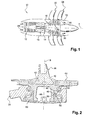
- FIG 1 represents a turbomachine 10 with unducted propellers (in English “open rotor” or “unducted fan”) which comprises from upstream to downstream, in the direction of flow of the gases inside the turbomachine, a compressor 12, an annular combustion chamber 14, a high-pressure turbine 16, and two low-pressure turbines 18, 20 which are counter-rotating, that is to say they rotate in two opposite directions about the longitudinal axis A of the turbomachine.
- unducted propellers in English “open rotor” or “unducted fan”
- Each of these downstream turbines 18, 20 is integral in rotation with an external helix 22, 24 extending radially outside the nacelle 26 of the turbomachine, this nacelle 26 being substantially cylindrical and extending along the outside.
- the flow of air 28 which enters the turbomachine is compressed and is mixed with fuel and burned in the combustion chamber 14, the combustion gases then passing into the turbines to rotate the propellers 22, 24 which provide the major part of the thrust generated by the turbomachine.
- the combustion gases leaving the turbines are expelled through a nozzle 32 (arrows 30) to increase the thrust.
- the propellers 22, 24 are arranged coaxially one behind the other and comprise a plurality of blades regularly distributed around the axis A of the turbomachine. These blades extend substantially radially and are of the variable-pitch type, that is to say that they can rotate about their axes so as to optimize their angular position as a function of the operating conditions of the turbomachine.
- each helix comprises a rotor element formed by a polygonal ring 34 which extends around the axis A and which comprises a plurality of substantially cylindrical radial housings 36 in which are engaged means for mounting the blades 38 of the propeller .
- Each blade 38 comprises at its radially inner end a dovetail-type section foot 40, which is engaged and retained in a groove 42 of a plate 44.
- the plate 44 comprises a cylindrical body 46 with an external thread 48 for its screwing from the outside into a ring 50 which is engaged in the housing 36 of the polygonal ring 34 from the inside, with respect to the longitudinal axis A of the turbomachine.
- the plate 44 and the ring 50 are centered and guided in rotation in the housing 36 by means of two roller bearings 52, 54.
- the housing 36 of the ring is divided into two parts, respectively radially inner and outer, by a rim inner ring 56 of the ring.
- a first roller bearing 52 is mounted radially outside this rim 56, between this rim and the plate 44.
- the second roller bearing 54 is mounted radially inside the rim 56, between this flange and the rim 50
- the plate 44 and the ring gear 50 are rotated about the radial axis B of the housing 36 by appropriate means which are not shown, to rotate the blade 38 around this axis and optimize its angular setting.
- the blades 38 are subjected to considerable centrifugal forces (up to 30,000 daN) which are transmitted from the blades to the polygonal ring 34 via the threads 48 of the plates and rings, which in general are not not designed to withstand such efforts. It would be possible to oversize these threads (no screws called “no artillery”) to resist these efforts but, mechanically, the support on nets (whatever their form) for the transmission of these efforts is not the best solution to ensure the durability and reliability required for aeronautical parts.
- the invention provides a solution to this problem through the sectorization of the crown and the nesting of the crown sectors in an outer annular groove of the body of the plate.
- FIGS. 3 to 5 represent an embodiment of a non-ducted propeller according to the invention, the blades of this propeller not being represented for greater clarity and being mounted on their support means in the same way as in the known art.
- the polygonal ring 134 of the propeller according to the invention is visible in its entirety in figure 3 . It comprises cylindrical housings 136 substantially radial, for example twelve in each of which are intended to be mounted a plate and a crown, as will be explained in more detail in the following.
- the polygonal ring 134 comprises a plurality of recesses 158 regularly distributed around the axis C of the ring and formed in the cylindrical wall of the ring to lighten it. Each recess 158 is located between two consecutive radial housings 136.
- FIGS. 4 and 5 are partial views on a larger scale of this polygonal ring 134, an axial section has been made substantially in the middle of a cylindrical housing 136 of the ring.
- the housing 136 of the ring is divided into two parts, respectively radially inner and outer, by an inner annular rim 156 of the ring.
- a first bearing 152 of the ball type in the example shown is mounted radially outside this flange 156, between this flange and the plate 144 to guide and center in rotation.
- the second bearing 154 which is also here of the ball type is mounted radially inside the flange 156, between this flange and the ring 150 to guide and center in rotation.
- the plate 144 is applied to the outer lateral face of the flange 156 via the bearing 152 and the ring gear 150 is applied to the internal lateral face of this flange 156 via the bearing 154.
- the ring gear 150 is sectored and comprises an annular flange 160 which extends radially inwards, with respect to the axis D of the housing, and which is engaged by interlocking in an annular groove 162 opening towards the outside the body of the plate 144.
- the mounting crown sectors 150 in the throat of the plate will be explained in detail in the following.
- the ring 150 comprises two sectors, one of which is visible in figure 5 .
- the width or axial dimension (measured along the axis D) of the rim 160 of the ring gear 150 is equal to or greater than the width or axial dimension (measured along the same axis) of the groove 162 of the plate 144, so that the rim 160 is engaged in the groove 162 with adjustment to very low tolerance of assembly, or even slightly in force.
- the internal diameter of the flange 160 of the ring gear 150 is also substantially equal to or even less than the internal diameter of the groove 162, so that, in the mounted position represented by figure 4 , this flange 160 is supported by its radially inner face (relative to the axis D) on the bottom of the groove 162.
- the ring 150 further comprises at its outer periphery a frustoconical outer surface 164 which widens radially outwards with respect to the axis C of the ring 134, and which cooperates with a frustoconical internal surface 166 of substantially complementary shape. of a one-piece ring 168 which is biased outwards (relative to the axis C) by a nut 170 screwed onto the body of the plate. The ring 168 is thus applied to the ring gear 150 by the nut 170.
- a locking washer 172 is interposed between the ring 168 and the nut 170 to immobilize in rotation this nut vis-à-vis the plate 144.
- This washer 172 comprises at its inner periphery first tabs 174 which are engaged in notches 176 of complementary shape of the body of the plate, to immobilize in rotation the washer vis-à-vis the plate.
- the washer 172 further comprises at its outer periphery second tabs 178 which are intended to be folded and engaged in notches 180 of complementary shape of the outer periphery of the nut 170, to immobilize in rotation the washer on the nut 170 .
- the washer 172 is engaged in the housing 136 by translation along the axis D, from the inside, and the nut 170 is screwed onto the body of the plate 144 from the inside.
- the ring and the aforementioned nut can be formed in one piece.
- the ring is then screwed onto the body of the plate and is supported by its frustoconical inner surface on the frustoconical outer surface of the crown.
- the plate 144 and the ring gear 150 are mounted in the housing 136 of the rotor element 134 in the following manner.
- the bearing 152 is engaged in the housing 136 from the outside and is supported on the outer lateral face of the inner rim 156 of the housing.
- the plate 144 is aligned on the axis D of the housing and is displaced by translation along this axis from the outside, until its body is engaged in the housing 136 and comes to rest by its radially outer end on the bearing 152.
- the second bearing 154 is engaged in the housing 136 from the inside and is supported on the inner side of the flange 156 of the housing.
- the ring sectors 150 are engaged one after the other from the inside in the annular passage 182 extending between the body of the plate 144 and an inner cylindrical surface 184 of the housing 136 until they are located at level of the groove 162 of the plate.
- the surface 184 extends here from the inner flange 156 to the radially inner end of the housing 136.
- Each crown sector 150 is then displaced in radial translation inwardly (by relative to the axis D) so that its internal rim 160 engages in the groove 162 and bears against the bottom of this groove 162.
- the aforementioned annular passage 182 has a radial dimension F (with respect to the axis D) sufficient to allow the engagement of each crown sector 150 by translation from the inside along the axis D.
- This radial dimension F ( figure 4 ) is determined in particular according to the inner and outer diameters of the crown and the angular extent of its sectors.
- an annular space is needed around the ring sectors 150 to remove the annular flange 160 of the groove 162 by moving the ring sectors in radial translation relative to the axis D outwardly.
- the space has a radial dimension E with respect to the axis D ( figure 5 ).
- the ring 150 has an internal diameter of 69 mm (corresponding to the internal diameter of its inner rim 160) and an outer diameter of 74.5 mm.
- the radial dimension E of the space must be approximately 7.5 mm.
- this dimension E is about 10 mm, and when their angular extent is 180 °, the dimension E is about 28 mm.
- the centrifugal forces to which the blades of the propeller are subjected are transmitted to the polygonal ring 134 via the plates 144, crowns 150 and bearings 154.
- the transmission of forces between the plates and the rings is provided by supporting the radially inner side wall of the groove 162 on the radially inner face of the flange 160 of the ring (in a direction parallel to the axis D), the groove 162 and the flange 160 being designed to withstand the forces supra.
- this ring further comprising a cylindrical flange 186 extending inwardly along the axis D.
- This flange 186 is supported by its inner cylindrical surface on an outer cylindrical surface 188 of the body of the plate which extends between the groove 162 and the radially inner end of this body. This support makes it possible to maintain in position the internal rim 160 of the ring gear 150 in the groove 162 of the plate when the centrifugal forces applied to the blade are important.
- the number of crown sectors is equal to three or four or more.
Landscapes
- Engineering & Computer Science (AREA)
- General Engineering & Computer Science (AREA)
- Mechanical Engineering (AREA)
- Aviation & Aerospace Engineering (AREA)
- Structures Of Non-Positive Displacement Pumps (AREA)
Claims (9)
- Verfahren zum Montieren eines nicht ummantelten Propellers mit Blättern mit veränderbarem Einstellwinkel bei einer Turbomaschine bzw. einem Turbotriebwerk, wobei die Blätter des Propellers um ihre Achsen drehbar in radialen Aufnahmeausnehmungen (136) eines ringförmigen Rotorteils (134) gelagert sind, wobei jedes Blatt von einer Platte (144) mit zylindrischem Körper getragen wird, dadurch gekennzeichnet, dass der zylindrische Körper von außen in eine radiale Aufnahmeausnehmung des Rotorteils eingreift und von einem Ringkranz (150) in dieser Aufnahmeausnehmung gehalten wird, wobei nach Eingreifen des Körpers der Platte in die Aufnahmeausnehmung der Kranz von innen in die Aufnahmeausnehmung montiert wird und über ein Lager (154) an eine innere Randleiste der Aufnahmeausnehmung angesetzt wird, wobei der Kranz unterteilt ausgeführt ist und einen radial inneren Abschnitt (160) aufweist, der durch Einstecken der Kranzsektoren in eine ringförmige Nut (162) der Außenfläche des Körpers der Platte eingreift.
- Verfahren nach Anspruch 1, dadurch gekennzeichnet, dass der Kranz (150) zwei Sektoren aufweist, die jeweils eine Winkelerstreckung von etwa 180° aufweisen, oder drei Sektoren, die jeweils eine Winkelerstreckung von etwa 120° aufweisen, oder vier Sektoren, die jeweils eine Winkelerstreckung von etwa 90° aufweisen.
- Verfahren nach einem der vorangehenden Ansprüche, dadurch gekennzeichnet, dass Mittel zum Sichern des Kranzes (150) in der Nut (162) des Körpers der Platte (144) von innerhalb der Aufnahmeausnehmung (136) an den Körper der Platte befestigt sind.
- Verfahren nach Anspruch 3, dadurch gekennzeichnet, dass der Kranz (150) eine kegelstumpfförmige Außenfläche (164) aufweist, die sich nach außen erweitert und an welche eine kegelstumpfförmige Innenfläche (166) angesetzt ist, die im wesentlichen komplementär zu einem Ring (168) ausgeführt ist, welcher von innen in die Aufnahmeausnehmung (136) eingreift und über eine an den Körper der Platte (144) angeschraubte Mutter (170) an den Kranz gedrückt wird.
- Verfahren nach Anspruch 4, dadurch gekennzeichnet, dass eine Sicherungsscheibe (172) zwischen Ring (168) und Mutter (170) eingefügt ist und erste Mittel (174), die durch Formschluss mit komplementären Mitteln (176) des Körpers der Platte (144) zusammenwirken, und zweite Mittel (178) aufweist, die durch Formschluss mit komplementären Mitteln (180) der Mutter zusammenwirken, um die Mutter gegenüber der Platte drehfest festzulegen.
- Verfahren nach Anspruch 3, dadurch gekennzeichnet, dass der Kranz eine kegelstumpfförmige Außenfläche aufweist, die sich nach außen erweitert und an welche eine im Wesentlichen komplementäre kegelstumpfförmige Innenfläche eines Rings angesetzt ist, der ein Innengewinde zum Anschrauben an den Körper der Platte aufweist.
- Verfahren nach einem der vorangehenden Ansprüche, dadurch gekennzeichnet, dass der Kranz (150) eine zylindrische Randleiste (186) aufweist, die sich gegenüber der Achse (D) der Aufnahmeausnehmung (136) axial nach innen erstreckt und an eine zylindrische Außenfläche des Körpers der Platte angesetzt ist.
- Verfahren nach einem der vorangehenden Ansprüche, dadurch gekennzeichnet, dass in montierter Stellung der Kranz (150) durch einen ringförmigen Raum von einer zylindrischen Innenfläche der Aufnahmeausnehmung getrennt ist.
- Verfahren nach einem der vorangehenden Ansprüche, dadurch gekennzeichnet, dass die innere Randleiste (156) der Aufnahmeausnehmung des Rotorteils (134) eine seitliche Innenfläche und eine seitliche Außenfläche aufweist, wobei der Kranz (150) über das entsprechende Lager (154) an die seitliche Innenfläche der Randleiste (156) angesetzt ist, wobei die Platte (144) über ein weiteres Lager (152) an die seitliche Außenfläche der Randleiste (156) angesetzt ist.
Applications Claiming Priority (2)
| Application Number | Priority Date | Filing Date | Title |
|---|---|---|---|
| FR0901344A FR2943313B1 (fr) | 2009-03-23 | 2009-03-23 | Helice non carenee a pales a calage variable pour une turbomachine |
| PCT/FR2010/000167 WO2010109085A1 (fr) | 2009-03-23 | 2010-02-23 | Hélice non carénée à pales à calage variable pour une turbomachine |
Publications (2)
| Publication Number | Publication Date |
|---|---|
| EP2411270A1 EP2411270A1 (de) | 2012-02-01 |
| EP2411270B1 true EP2411270B1 (de) | 2014-12-17 |
Family
ID=41404356
Family Applications (1)
| Application Number | Title | Priority Date | Filing Date |
|---|---|---|---|
| EP10708250.5A Active EP2411270B1 (de) | 2009-03-23 | 2010-02-23 | Düsenloser fan für turbomaschine mit schaufeln mit einstellbarem winkel |
Country Status (9)
| Country | Link |
|---|---|
| US (1) | US8827653B2 (de) |
| EP (1) | EP2411270B1 (de) |
| JP (1) | JP5529253B2 (de) |
| CN (1) | CN102361792B (de) |
| BR (1) | BRPI1013581B1 (de) |
| CA (1) | CA2755653A1 (de) |
| FR (1) | FR2943313B1 (de) |
| RU (1) | RU2516957C2 (de) |
| WO (1) | WO2010109085A1 (de) |
Families Citing this family (23)
| Publication number | Priority date | Publication date | Assignee | Title |
|---|---|---|---|---|
| FR2947590B1 (fr) | 2009-07-02 | 2011-07-15 | Snecma | Moyeu d'helice |
| FR2948973B1 (fr) | 2009-08-05 | 2011-10-14 | Snecma | Moyeu d'helice a pales a calage variable |
| FR2958621B1 (fr) * | 2010-04-09 | 2012-03-23 | Snecma | Helice non carenee pour turbomachine. |
| FR2993919B1 (fr) * | 2012-07-25 | 2014-07-11 | Snecma | Helice non carenee a pales a calage variable pour une turbomachine |
| WO2014066503A1 (en) * | 2012-10-23 | 2014-05-01 | General Electric Company | Unducted thrust producing system |
| FR3017163B1 (fr) * | 2014-02-04 | 2016-02-12 | Snecma | Dispositif pour une helice non carenee a pales a calage variable d'une turbomachine |
| US9869190B2 (en) | 2014-05-30 | 2018-01-16 | General Electric Company | Variable-pitch rotor with remote counterweights |
| US10072510B2 (en) | 2014-11-21 | 2018-09-11 | General Electric Company | Variable pitch fan for gas turbine engine and method of assembling the same |
| US20160290228A1 (en) * | 2015-04-06 | 2016-10-06 | General Electric Company | Fan bearings for a turbine engine |
| US10077674B2 (en) * | 2015-06-23 | 2018-09-18 | General Electric Company | Trunnion retention for a turbine engine |
| US10100653B2 (en) | 2015-10-08 | 2018-10-16 | General Electric Company | Variable pitch fan blade retention system |
| RU2667670C2 (ru) * | 2016-07-06 | 2018-09-24 | Гафтдин Газдалиевич Газдалиев | Движитель с меняющимися лопастями |
| IT201800006989A1 (it) * | 2018-07-06 | 2020-01-06 | Sincronizzatore per trasmissione meccanica, particolarmente per trasmissione di veicolo. | |
| FR3093076B1 (fr) * | 2019-02-22 | 2021-04-02 | Safran Aircraft Engines | Pivot d’aube à orientation réglable et à encombrement réduit pour moyeu de soufflante de turbomachine |
| IL286195B2 (en) | 2019-04-23 | 2025-04-01 | Cr Flight L L C | Assembly of a rotating axial electric motor |
| FR3104540B1 (fr) * | 2019-12-11 | 2021-12-17 | Safran Aircraft Engines | Perfectionnement au verrouillage radial d’un pivot d’aube à orientation réglable pour moyeu de soufflante de turbomachine |
| US11674435B2 (en) | 2021-06-29 | 2023-06-13 | General Electric Company | Levered counterweight feathering system |
| US11795964B2 (en) | 2021-07-16 | 2023-10-24 | General Electric Company | Levered counterweight feathering system |
| US12320391B2 (en) * | 2022-10-19 | 2025-06-03 | GM Global Technology Operations LLC | External snap ring retainer |
| US12601271B2 (en) | 2022-10-21 | 2026-04-14 | General Electric Company | Variable pitch fan of a gas turbine engine |
| US12264590B2 (en) | 2023-08-08 | 2025-04-01 | General Electric Company | Fan assembly for an engine having redundant trunnion retention |
| US12546226B1 (en) | 2024-08-07 | 2026-02-10 | General Electric Company | Variable pitch fan blade retention system |
| GB2643448A (en) * | 2024-08-15 | 2026-02-18 | Jaguar Land Rover Ltd | Bearing retention sleeve |
Family Cites Families (13)
| Publication number | Priority date | Publication date | Assignee | Title |
|---|---|---|---|---|
| US2248590A (en) * | 1937-11-15 | 1941-07-08 | John W Smith | Aeronautical propeller blade mounting |
| US3985406A (en) * | 1973-07-18 | 1976-10-12 | Marion Power Shovel Company, Inc. | Cushioned roller circle |
| US4082378A (en) * | 1975-07-14 | 1978-04-04 | General Electric Company | Deformable bearing seat |
| US4863352A (en) * | 1984-11-02 | 1989-09-05 | General Electric Company | Blade carrying means |
| FR2605586B1 (fr) * | 1986-10-22 | 1990-11-30 | Snecma | Anneau porte-pales pour aubage d'helice de grande dimension |
| US5263898A (en) * | 1988-12-14 | 1993-11-23 | General Electric Company | Propeller blade retention system |
| US5051693A (en) * | 1990-09-07 | 1991-09-24 | The Torrington Company | Bearing seat encoder mount for rotational parameter sensor apparatus |
| DE9206149U1 (de) * | 1992-05-07 | 1992-07-30 | Helmut Elges GmbH, 4800 Bielefeld | Festsetzbare Gelenklager |
| US6015264A (en) * | 1997-08-15 | 2000-01-18 | United Technologies Corporation | Preloaded retention assembly for aircraft propeller blade retention |
| RU17912U1 (ru) * | 2001-02-14 | 2001-05-10 | Общество с ограниченной ответственностью "ЭЛИТАР-101" | Воздушный винт изменяемого шага |
| DE20116649U1 (de) * | 2001-10-10 | 2001-12-06 | AB SKF, Göteborg | Lager, insbesondere Wälzlager |
| GB0712561D0 (en) * | 2007-06-28 | 2007-08-08 | Rolls Royce Plc | A blade mounting |
| FR2943312B1 (fr) | 2009-03-23 | 2011-05-27 | Snecma | Helice non carenee a pales a calage variable pour une turbomachine |
-
2009
- 2009-03-23 FR FR0901344A patent/FR2943313B1/fr active Active
-
2010
- 2010-02-23 CN CN201080013666.0A patent/CN102361792B/zh active Active
- 2010-02-23 US US13/258,481 patent/US8827653B2/en active Active
- 2010-02-23 CA CA2755653A patent/CA2755653A1/fr not_active Abandoned
- 2010-02-23 EP EP10708250.5A patent/EP2411270B1/de active Active
- 2010-02-23 WO PCT/FR2010/000167 patent/WO2010109085A1/fr not_active Ceased
- 2010-02-23 JP JP2012501335A patent/JP5529253B2/ja not_active Expired - Fee Related
- 2010-02-23 RU RU2011142787/11A patent/RU2516957C2/ru active
- 2010-02-23 BR BRPI1013581-2A patent/BRPI1013581B1/pt active IP Right Grant
Also Published As
| Publication number | Publication date |
|---|---|
| US20120045334A1 (en) | 2012-02-23 |
| RU2011142787A (ru) | 2013-04-27 |
| JP5529253B2 (ja) | 2014-06-25 |
| FR2943313B1 (fr) | 2011-05-27 |
| RU2516957C2 (ru) | 2014-05-20 |
| CN102361792B (zh) | 2015-04-22 |
| CA2755653A1 (fr) | 2010-09-30 |
| WO2010109085A1 (fr) | 2010-09-30 |
| CN102361792A (zh) | 2012-02-22 |
| EP2411270A1 (de) | 2012-02-01 |
| JP2012521516A (ja) | 2012-09-13 |
| BRPI1013581A2 (pt) | 2016-04-12 |
| BRPI1013581B1 (pt) | 2020-07-07 |
| FR2943313A1 (fr) | 2010-09-24 |
| US8827653B2 (en) | 2014-09-09 |
Similar Documents
| Publication | Publication Date | Title |
|---|---|---|
| WO2010109085A1 (fr) | Hélice non carénée à pales à calage variable pour une turbomachine | |
| EP2555973B1 (de) | Nichtverkleideter rotor für eine gasturbine | |
| FR2943312A1 (fr) | Helice non carenee a pales a calage variable pour une turbomachine | |
| EP3927617B1 (de) | Platzsparender und verstellbarer schaufelzapfen für turbomaschinen | |
| FR3017163A1 (fr) | Dispositif pour une helice non carenee a pales a calage variable d'une turbomachine | |
| FR3032941A1 (fr) | Soufflante non carenee de turbomachine d'aeronef | |
| FR3017667A1 (fr) | Dispositif pour une helice non carenee a pales a calage variable d'une turbomachine | |
| EP2462352B1 (de) | Propellernabe für verstellbare schaufeln | |
| FR3138806A1 (fr) | Helice pour une turbomachine d’aeronef | |
| WO2011000943A1 (fr) | Moyeu d'helice | |
| FR2914944A1 (fr) | Calage variable d'aubes de compresseur dans une turbomachine | |
| FR2915550A1 (fr) | Vanne a clapet pour un systeme de refroidissement dans une turbomachine | |
| EP4010563B1 (de) | Prallkühlvorrichtung für ein turbomaschinen-aussengehäuse und turbomaschine mit entsprechender vorrichtung | |
| FR2944774A1 (fr) | Helice non carenee a pales a calage variable pour une turbomachine | |
| WO2021116566A1 (fr) | Perfectionnement au verrouillage radial d'un pivot d'aube à orientation réglable pour moyeu de soufflante de turbomachine | |
| FR2983924A1 (fr) | Carter annulaire pour un compresseur de turbomachine | |
| EP4363313A1 (de) | Propeller für ein turbinentriebwerk eines flugzeugs mit einer verstellschaufel und einer getriebegegengewichtsvorrichtung | |
| EP3914809A1 (de) | Unterbaugruppe zur montage eines führungslagers einer verdichterwelle | |
| FR3026776B1 (fr) | Dispositif de transmission de puissance pour une turbomachine d'aeronef | |
| EP4010566B1 (de) | Turbinentriebwerksverdichter für flugzeuge mit einer vorrichtung zum fixieren eines halteringes | |
| FR3093538A1 (fr) | Sous ensemble de montage d'un palier de guidage d'un arbre de compresseur | |
| WO2025242985A1 (fr) | Dispositif de fixation de modules de turbomachine | |
| WO2026078339A1 (fr) | Ensemble propulsif pour un aeronef | |
| WO2026013345A1 (fr) | Systeme d'accouplement ameliore de deux pieces de turbomachine d'aeronef, de preference deux arbres de turbomachine |
Legal Events
| Date | Code | Title | Description |
|---|---|---|---|
| PUAI | Public reference made under article 153(3) epc to a published international application that has entered the european phase |
Free format text: ORIGINAL CODE: 0009012 |
|
| 17P | Request for examination filed |
Effective date: 20110830 |
|
| AK | Designated contracting states |
Kind code of ref document: A1 Designated state(s): AT BE BG CH CY CZ DE DK EE ES FI FR GB GR HR HU IE IS IT LI LT LU LV MC MK MT NL NO PL PT RO SE SI SK SM TR |
|
| DAX | Request for extension of the european patent (deleted) | ||
| 17Q | First examination report despatched |
Effective date: 20130305 |
|
| GRAP | Despatch of communication of intention to grant a patent |
Free format text: ORIGINAL CODE: EPIDOSNIGR1 |
|
| INTG | Intention to grant announced |
Effective date: 20140320 |
|
| RIN1 | Information on inventor provided before grant (corrected) |
Inventor name: BOSTON, ERIC, JACQUES Inventor name: JABLONSKI, LAURENT Inventor name: JOLY, PHILIPPE Inventor name: BOURU, MICHEL, ANDRE |
|
| GRAS | Grant fee paid |
Free format text: ORIGINAL CODE: EPIDOSNIGR3 |
|
| GRAP | Despatch of communication of intention to grant a patent |
Free format text: ORIGINAL CODE: EPIDOSNIGR1 |
|
| INTG | Intention to grant announced |
Effective date: 20140806 |
|
| GRAA | (expected) grant |
Free format text: ORIGINAL CODE: 0009210 |
|
| AK | Designated contracting states |
Kind code of ref document: B1 Designated state(s): AT BE BG CH CY CZ DE DK EE ES FI FR GB GR HR HU IE IS IT LI LT LU LV MC MK MT NL NO PL PT RO SE SI SK SM TR |
|
| REG | Reference to a national code |
Ref country code: GB Ref legal event code: FG4D Free format text: NOT ENGLISH |
|
| REG | Reference to a national code |
Ref country code: CH Ref legal event code: EP |
|
| REG | Reference to a national code |
Ref country code: IE Ref legal event code: FG4D Free format text: LANGUAGE OF EP DOCUMENT: FRENCH |
|
| REG | Reference to a national code |
Ref country code: AT Ref legal event code: REF Ref document number: 701681 Country of ref document: AT Kind code of ref document: T Effective date: 20150115 |
|
| REG | Reference to a national code |
Ref country code: DE Ref legal event code: R096 Ref document number: 602010021031 Country of ref document: DE Effective date: 20150212 |
|
| REG | Reference to a national code |
Ref country code: FR Ref legal event code: PLFP Year of fee payment: 6 |
|
| REG | Reference to a national code |
Ref country code: SE Ref legal event code: TRGR |
|
| PG25 | Lapsed in a contracting state [announced via postgrant information from national office to epo] |
Ref country code: LT Free format text: LAPSE BECAUSE OF FAILURE TO SUBMIT A TRANSLATION OF THE DESCRIPTION OR TO PAY THE FEE WITHIN THE PRESCRIBED TIME-LIMIT Effective date: 20141217 Ref country code: FI Free format text: LAPSE BECAUSE OF FAILURE TO SUBMIT A TRANSLATION OF THE DESCRIPTION OR TO PAY THE FEE WITHIN THE PRESCRIBED TIME-LIMIT Effective date: 20141217 Ref country code: NO Free format text: LAPSE BECAUSE OF FAILURE TO SUBMIT A TRANSLATION OF THE DESCRIPTION OR TO PAY THE FEE WITHIN THE PRESCRIBED TIME-LIMIT Effective date: 20150317 |
|
| REG | Reference to a national code |
Ref country code: LT Ref legal event code: MG4D |
|
| PG25 | Lapsed in a contracting state [announced via postgrant information from national office to epo] |
Ref country code: HR Free format text: LAPSE BECAUSE OF FAILURE TO SUBMIT A TRANSLATION OF THE DESCRIPTION OR TO PAY THE FEE WITHIN THE PRESCRIBED TIME-LIMIT Effective date: 20141217 Ref country code: GR Free format text: LAPSE BECAUSE OF FAILURE TO SUBMIT A TRANSLATION OF THE DESCRIPTION OR TO PAY THE FEE WITHIN THE PRESCRIBED TIME-LIMIT Effective date: 20150318 Ref country code: LV Free format text: LAPSE BECAUSE OF FAILURE TO SUBMIT A TRANSLATION OF THE DESCRIPTION OR TO PAY THE FEE WITHIN THE PRESCRIBED TIME-LIMIT Effective date: 20141217 |
|
| REG | Reference to a national code |
Ref country code: AT Ref legal event code: MK05 Ref document number: 701681 Country of ref document: AT Kind code of ref document: T Effective date: 20141217 |
|
| PG25 | Lapsed in a contracting state [announced via postgrant information from national office to epo] |
Ref country code: NL Free format text: LAPSE BECAUSE OF FAILURE TO SUBMIT A TRANSLATION OF THE DESCRIPTION OR TO PAY THE FEE WITHIN THE PRESCRIBED TIME-LIMIT Effective date: 20141217 |
|
| PG25 | Lapsed in a contracting state [announced via postgrant information from national office to epo] |
Ref country code: SK Free format text: LAPSE BECAUSE OF FAILURE TO SUBMIT A TRANSLATION OF THE DESCRIPTION OR TO PAY THE FEE WITHIN THE PRESCRIBED TIME-LIMIT Effective date: 20141217 Ref country code: ES Free format text: LAPSE BECAUSE OF FAILURE TO SUBMIT A TRANSLATION OF THE DESCRIPTION OR TO PAY THE FEE WITHIN THE PRESCRIBED TIME-LIMIT Effective date: 20141217 Ref country code: EE Free format text: LAPSE BECAUSE OF FAILURE TO SUBMIT A TRANSLATION OF THE DESCRIPTION OR TO PAY THE FEE WITHIN THE PRESCRIBED TIME-LIMIT Effective date: 20141217 Ref country code: CZ Free format text: LAPSE BECAUSE OF FAILURE TO SUBMIT A TRANSLATION OF THE DESCRIPTION OR TO PAY THE FEE WITHIN THE PRESCRIBED TIME-LIMIT Effective date: 20141217 Ref country code: RO Free format text: LAPSE BECAUSE OF FAILURE TO SUBMIT A TRANSLATION OF THE DESCRIPTION OR TO PAY THE FEE WITHIN THE PRESCRIBED TIME-LIMIT Effective date: 20141217 |
|
| PG25 | Lapsed in a contracting state [announced via postgrant information from national office to epo] |
Ref country code: AT Free format text: LAPSE BECAUSE OF FAILURE TO SUBMIT A TRANSLATION OF THE DESCRIPTION OR TO PAY THE FEE WITHIN THE PRESCRIBED TIME-LIMIT Effective date: 20141217 Ref country code: IS Free format text: LAPSE BECAUSE OF FAILURE TO SUBMIT A TRANSLATION OF THE DESCRIPTION OR TO PAY THE FEE WITHIN THE PRESCRIBED TIME-LIMIT Effective date: 20150417 Ref country code: PL Free format text: LAPSE BECAUSE OF FAILURE TO SUBMIT A TRANSLATION OF THE DESCRIPTION OR TO PAY THE FEE WITHIN THE PRESCRIBED TIME-LIMIT Effective date: 20141217 |
|
| REG | Reference to a national code |
Ref country code: DE Ref legal event code: R097 Ref document number: 602010021031 Country of ref document: DE |
|
| PG25 | Lapsed in a contracting state [announced via postgrant information from national office to epo] |
Ref country code: LU Free format text: LAPSE BECAUSE OF FAILURE TO SUBMIT A TRANSLATION OF THE DESCRIPTION OR TO PAY THE FEE WITHIN THE PRESCRIBED TIME-LIMIT Effective date: 20150223 |
|
| REG | Reference to a national code |
Ref country code: CH Ref legal event code: PL |
|
| PLBE | No opposition filed within time limit |
Free format text: ORIGINAL CODE: 0009261 |
|
| STAA | Information on the status of an ep patent application or granted ep patent |
Free format text: STATUS: NO OPPOSITION FILED WITHIN TIME LIMIT |
|
| PG25 | Lapsed in a contracting state [announced via postgrant information from national office to epo] |
Ref country code: CH Free format text: LAPSE BECAUSE OF NON-PAYMENT OF DUE FEES Effective date: 20150228 Ref country code: MC Free format text: LAPSE BECAUSE OF FAILURE TO SUBMIT A TRANSLATION OF THE DESCRIPTION OR TO PAY THE FEE WITHIN THE PRESCRIBED TIME-LIMIT Effective date: 20141217 Ref country code: LI Free format text: LAPSE BECAUSE OF NON-PAYMENT OF DUE FEES Effective date: 20150228 Ref country code: DK Free format text: LAPSE BECAUSE OF FAILURE TO SUBMIT A TRANSLATION OF THE DESCRIPTION OR TO PAY THE FEE WITHIN THE PRESCRIBED TIME-LIMIT Effective date: 20141217 |
|
| REG | Reference to a national code |
Ref country code: IE Ref legal event code: MM4A |
|
| 26N | No opposition filed |
Effective date: 20150918 |
|
| PG25 | Lapsed in a contracting state [announced via postgrant information from national office to epo] |
Ref country code: IE Free format text: LAPSE BECAUSE OF NON-PAYMENT OF DUE FEES Effective date: 20150223 |
|
| REG | Reference to a national code |
Ref country code: FR Ref legal event code: PLFP Year of fee payment: 7 |
|
| PG25 | Lapsed in a contracting state [announced via postgrant information from national office to epo] |
Ref country code: SI Free format text: LAPSE BECAUSE OF FAILURE TO SUBMIT A TRANSLATION OF THE DESCRIPTION OR TO PAY THE FEE WITHIN THE PRESCRIBED TIME-LIMIT Effective date: 20141217 |
|
| PG25 | Lapsed in a contracting state [announced via postgrant information from national office to epo] |
Ref country code: MT Free format text: LAPSE BECAUSE OF FAILURE TO SUBMIT A TRANSLATION OF THE DESCRIPTION OR TO PAY THE FEE WITHIN THE PRESCRIBED TIME-LIMIT Effective date: 20141217 |
|
| REG | Reference to a national code |
Ref country code: FR Ref legal event code: PLFP Year of fee payment: 8 |
|
| PG25 | Lapsed in a contracting state [announced via postgrant information from national office to epo] |
Ref country code: BG Free format text: LAPSE BECAUSE OF FAILURE TO SUBMIT A TRANSLATION OF THE DESCRIPTION OR TO PAY THE FEE WITHIN THE PRESCRIBED TIME-LIMIT Effective date: 20141217 Ref country code: SM Free format text: LAPSE BECAUSE OF FAILURE TO SUBMIT A TRANSLATION OF THE DESCRIPTION OR TO PAY THE FEE WITHIN THE PRESCRIBED TIME-LIMIT Effective date: 20141217 Ref country code: HU Free format text: LAPSE BECAUSE OF FAILURE TO SUBMIT A TRANSLATION OF THE DESCRIPTION OR TO PAY THE FEE WITHIN THE PRESCRIBED TIME-LIMIT; INVALID AB INITIO Effective date: 20100223 |
|
| PG25 | Lapsed in a contracting state [announced via postgrant information from national office to epo] |
Ref country code: CY Free format text: LAPSE BECAUSE OF FAILURE TO SUBMIT A TRANSLATION OF THE DESCRIPTION OR TO PAY THE FEE WITHIN THE PRESCRIBED TIME-LIMIT Effective date: 20141217 |
|
| PG25 | Lapsed in a contracting state [announced via postgrant information from national office to epo] |
Ref country code: BE Free format text: LAPSE BECAUSE OF NON-PAYMENT OF DUE FEES Effective date: 20150228 Ref country code: PT Free format text: LAPSE BECAUSE OF FAILURE TO SUBMIT A TRANSLATION OF THE DESCRIPTION OR TO PAY THE FEE WITHIN THE PRESCRIBED TIME-LIMIT Effective date: 20150417 |
|
| PG25 | Lapsed in a contracting state [announced via postgrant information from national office to epo] |
Ref country code: TR Free format text: LAPSE BECAUSE OF FAILURE TO SUBMIT A TRANSLATION OF THE DESCRIPTION OR TO PAY THE FEE WITHIN THE PRESCRIBED TIME-LIMIT Effective date: 20141217 |
|
| REG | Reference to a national code |
Ref country code: FR Ref legal event code: PLFP Year of fee payment: 9 |
|
| REG | Reference to a national code |
Ref country code: FR Ref legal event code: CD Owner name: SAFRAN AIRCRAFT ENGINES, FR Effective date: 20170719 |
|
| PG25 | Lapsed in a contracting state [announced via postgrant information from national office to epo] |
Ref country code: MK Free format text: LAPSE BECAUSE OF FAILURE TO SUBMIT A TRANSLATION OF THE DESCRIPTION OR TO PAY THE FEE WITHIN THE PRESCRIBED TIME-LIMIT Effective date: 20141217 |
|
| PGFP | Annual fee paid to national office [announced via postgrant information from national office to epo] |
Ref country code: SE Payment date: 20240123 Year of fee payment: 15 |
|
| REG | Reference to a national code |
Ref country code: SE Ref legal event code: EUG |
|
| PGFP | Annual fee paid to national office [announced via postgrant information from national office to epo] |
Ref country code: GB Payment date: 20260219 Year of fee payment: 17 |
|
| PGFP | Annual fee paid to national office [announced via postgrant information from national office to epo] |
Ref country code: DE Payment date: 20260217 Year of fee payment: 17 |
|
| PGFP | Annual fee paid to national office [announced via postgrant information from national office to epo] |
Ref country code: IT Payment date: 20260227 Year of fee payment: 17 |
|
| PGFP | Annual fee paid to national office [announced via postgrant information from national office to epo] |
Ref country code: FR Payment date: 20260213 Year of fee payment: 17 |