EP2411273B1 - Unites modulaires amenageables - Google Patents
Unites modulaires amenageables Download PDFInfo
- Publication number
- EP2411273B1 EP2411273B1 EP10708520A EP10708520A EP2411273B1 EP 2411273 B1 EP2411273 B1 EP 2411273B1 EP 10708520 A EP10708520 A EP 10708520A EP 10708520 A EP10708520 A EP 10708520A EP 2411273 B1 EP2411273 B1 EP 2411273B1
- Authority
- EP
- European Patent Office
- Prior art keywords
- monument
- cabin
- transportation means
- attachment
- transport
- Prior art date
- Legal status (The legal status is an assumption and is not a legal conclusion. Google has not performed a legal analysis and makes no representation as to the accuracy of the status listed.)
- Not-in-force
Links
Images






Classifications
-
- B—PERFORMING OPERATIONS; TRANSPORTING
- B64—AIRCRAFT; AVIATION; COSMONAUTICS
- B64D—EQUIPMENT FOR FITTING IN OR TO AIRCRAFT; FLIGHT SUITS; PARACHUTES; ARRANGEMENT OR MOUNTING OF POWER PLANTS OR PROPULSION TRANSMISSIONS IN AIRCRAFT
- B64D11/00—Passenger or crew accommodation; Flight-deck installations not otherwise provided for
- B64D11/04—Galleys
-
- B—PERFORMING OPERATIONS; TRANSPORTING
- B61—RAILWAYS
- B61D—BODY DETAILS OR KINDS OF RAILWAY VEHICLES
- B61D35/00—Sanitation
-
- B—PERFORMING OPERATIONS; TRANSPORTING
- B61—RAILWAYS
- B61D—BODY DETAILS OR KINDS OF RAILWAY VEHICLES
- B61D37/00—Other furniture or furnishings
-
- B—PERFORMING OPERATIONS; TRANSPORTING
- B61—RAILWAYS
- B61D—BODY DETAILS OR KINDS OF RAILWAY VEHICLES
- B61D37/00—Other furniture or furnishings
- B61D37/006—Other furniture or furnishings for restaurant cars or the like
-
- B—PERFORMING OPERATIONS; TRANSPORTING
- B64—AIRCRAFT; AVIATION; COSMONAUTICS
- B64D—EQUIPMENT FOR FITTING IN OR TO AIRCRAFT; FLIGHT SUITS; PARACHUTES; ARRANGEMENT OR MOUNTING OF POWER PLANTS OR PROPULSION TRANSMISSIONS IN AIRCRAFT
- B64D11/00—Passenger or crew accommodation; Flight-deck installations not otherwise provided for
- B64D11/003—Stowage devices for passengers' personal luggage
-
- B—PERFORMING OPERATIONS; TRANSPORTING
- B64—AIRCRAFT; AVIATION; COSMONAUTICS
- B64D—EQUIPMENT FOR FITTING IN OR TO AIRCRAFT; FLIGHT SUITS; PARACHUTES; ARRANGEMENT OR MOUNTING OF POWER PLANTS OR PROPULSION TRANSMISSIONS IN AIRCRAFT
- B64D11/00—Passenger or crew accommodation; Flight-deck installations not otherwise provided for
- B64D11/02—Toilet fittings
-
- B—PERFORMING OPERATIONS; TRANSPORTING
- B64—AIRCRAFT; AVIATION; COSMONAUTICS
- B64D—EQUIPMENT FOR FITTING IN OR TO AIRCRAFT; FLIGHT SUITS; PARACHUTES; ARRANGEMENT OR MOUNTING OF POWER PLANTS OR PROPULSION TRANSMISSIONS IN AIRCRAFT
- B64D11/00—Passenger or crew accommodation; Flight-deck installations not otherwise provided for
- B64D2011/0046—Modular or preassembled units for creating cabin interior structures
-
- Y—GENERAL TAGGING OF NEW TECHNOLOGICAL DEVELOPMENTS; GENERAL TAGGING OF CROSS-SECTIONAL TECHNOLOGIES SPANNING OVER SEVERAL SECTIONS OF THE IPC; TECHNICAL SUBJECTS COVERED BY FORMER USPC CROSS-REFERENCE ART COLLECTIONS [XRACs] AND DIGESTS
- Y02—TECHNOLOGIES OR APPLICATIONS FOR MITIGATION OR ADAPTATION AGAINST CLIMATE CHANGE
- Y02T—CLIMATE CHANGE MITIGATION TECHNOLOGIES RELATED TO TRANSPORTATION
- Y02T50/00—Aeronautics or air transport
- Y02T50/40—Weight reduction
Definitions
- the invention relates to the equipment of transport cabins.
- this invention relates to a monument for a cabin of a means of transport, such as a toilet monument, a kitchen monument or a storage monument for equipping an airplane, a helicopter, a ship, a train or a caravan.
- the invention relates to a built-in system with one or more monuments and a means of transport with a built-in monument.
- Such monuments can be fastened in means of transport, for example airplanes, to so-called "hard points".
- a hard point is a point of attachment created for a particular monument, which may be holes in a structural element of the transport. These hard points may have different diameters for different monuments, such as a kitchen element and a toilet monument, or may be provided for receiving various fasteners, such as screws or clamps.
- the attachment of the monuments to the aircraft fuselage is not standardized, but specifically tailored to the integration of the special monument into the aircraft.
- the attachment of monuments differs from the attachment of storage compartments.
- connections of monuments to on-board systems are not standardized.
- the cables and pipes to the connections are specially laid to the pitch of a monument.
- gaps between the side panel and a monument are filled by trim pieces. Often this leads to a large number of cut parts.
- the DE 10 2005 043 610 A1 and the US 2007 102579 A1 describe a monument to an airplane.
- the monument comprises fastening elements for fastening the monument to corresponding fastening elements of an aircraft surface in an aircraft at a predetermined location.
- the US 5 083 727 A forms the closest prior art and relates to a cabin system for an aircraft, in which galleys can be attached to seat rails.
- the galleys have flexible conduit connections.
- the DE 10 2007 029 677 A1 concerns a compartment system with sleepers that can be overridden by a container.
- the DE 10 2007 003 802 A1 relates to a flexible cable connection with chain links for a monument in an aircraft.
- the EP 1 174 340 A2 relates to an automatic system for storing galley cars.
- the DE 101 64 068 A1 relates to variably positionable vehicle seats for a road vehicle with an inductive energy and information transmission system.
- the US 2007/0262212 A1 relates to a monument fitting arrangement with which a monument can be installed in an aircraft.
- the EP 1 803 645 A1 relates to a module for an aircraft with a supply connection routed in a rail.
- the DE 10 2006 048 998 A1 relates to a telescopically extendable luggage compartment.
- a monument for a cabin of a means of transport comprises a fastening element for fastening the monument to the cabin or a supporting structure of the hull of the means of transport, Heiquess a supply connection for connecting the monument with at least one on-board system of the means of transport, wherein the fastening element is designed in such a way that the attachment of the monument can be made in a range of relative positions of the monument to the cabin of the means of transport, wherein the fastening element is connectable to a seat rail of the transport means, wherein the supply connection is a monument.
- Connecting end has, which is connectable to a transport medium connection end of the board system, wherein the Monument-AuMedicende is relative to the Monument zuzegbar by the monument. Connecting end can be moved along an opening of the monument.
- the adaptation effort is shifted from the cabin of the means of transport to the monument.
- the adaptation effort is reduced by the fact that the flexible fastening means can be adapted with little effort to the mounting location of the monument in the means of transport.
- the flexible fastener allows the monument to be secured within a range of relative positions within the cab of the transport without the need for significant changes to the cab.
- the adjustment effort which arises from the fact that the cabin has to be adapted to the male monument, is eliminated.
- the flexible fastener is attached to frames or girders of the fuselage of the aircraft or ship.
- At least one flexible fastening element and a plurality of flexible fastening elements is possible, which can be attached to the monument or integrated into the monument.
- the fastening element can be connected to a mounting rail for a storage compartment.
- the storage compartment may be for Example, an overhead storage compartment, such as a luggage rack act.
- An attachment rail for storage compartments is usually already present in each cabin of the means of transport, so that separate attachment points for the monument accounts.
- the fastening element can be connected to a seat rail of the transport means.
- seat rails In cabins of transport often seat rails are already available with which seats or rows of seats for passengers on the ground or the floor support structure of the means of transport can be attached.
- By attaching the monument to the seat rails account for separate, special attachment points for the monument.
- the monument has lower, possibly flexible fastening elements for fastening the monument to a floor support structure in a floor of the cabin.
- the monument has upper, possibly flexible fastening elements for attachment to a side support structure or roof support structure of the cabin.
- the monument may be fastened with a plurality of fastening elements in the cabin of the means of transport.
- a plurality of fastening elements in the cabin of the means of transport.
- an upper fastening element on a mounting rail for a storage compartment and a lower fastening element on a seat rail.
- the flexible fastening element comprises a fastening rail.
- This mounting rail can be mounted, for example, at the top of the monument and possibly run after installation parallel to the transport axis.
- one or more terminals can be arranged which are displaceable within the mounting rail.
- the monument further comprises fastening elements for fastening the monument to a floor of the cabin and a load distributing substructure, wherein the load distributing substructure is suitable for uniformly distributing forces which the monument exerts on the fastening elements and the ground.
- the monument can be arranged or placed at different locations within the cabin without the ground area loaded by the monument being specially prepared for the monument.
- the load distributing substructure comprises a base plate, which may have a larger base area than the monument for load distribution.
- the monument comprises a transport carriage, a receiving area for the transport carriage, wherein the transport carriage can be moved in and out of the receiving area, wherein the bottom plate comprises a wedge-shaped portion which serves as a ramp for the transport vehicle in the receiving area.
- a monument can be thought of a kitchen monument or galley and one or more trolleys as a transport vehicle. Through the ramp, a bottom plate can be selected of a thickness that would hinder the retraction and extension of the trolleys without the ramp, but optimally distributed by their thickness, the load.
- the monument comprises at least one supply connection for connecting the monument to at least one onboard system of the means of transport, wherein the supply connection is a monument connection end which is connectable to a transport terminal end of the onboard system, wherein the Monument terminal end is movable relative to the monument.
- the transport terminal end When installing the monument, the transport terminal end does not need to be specially adapted to the position of the monument, such as laying pipes or pipes, but the monument terminal end is merely moved toward and connected to the transport terminal end.
- the monument can be connected to a variety of onboard systems, for example to a power grid, a service water system, a sewer system or a data network (in which the connection can be done for example by means of glass fibers). It is therefore a "flexible" supply connection.
- the monument terminal end is movable in the horizontal direction or in the case of a built-in monument, it can be moved in the direction of the longitudinal axis of the transport means.
- a monument for a means of transport which comprises at least one connecting element for connecting the monument to the transport means, wherein the at least one connecting element is movable relative to the monument.
- the connecting element may for example be a clamp for a rail or a connection end to an on-board system of the means of transport.
- the monument terminal end is connectable to the transport terminal end suitable for connection to a storage compartment terminal end.
- transport connection ends account for separate connection end for monuments and storage compartments.
- the supply connection of the monument is arranged laterally on the rear wall, that is to say the wall which is intended to indicate the outer wall of the transport means.
- the monument comprises an induction loop, via which the monument can be supplied with electricity by means of an induction loop of the means of transport.
- a chain of induction loops can be arranged, which are also suitable for supplying power to seats fixed in the means of transport.
- the invention also relates to a mounting system for installation in a means of transport, which comprises a monument according to the invention.
- the installation system comprises at least two storage compartments whose extension in the transport longitudinal direction differ from each other.
- the two storage compartments have a different length.
- the mounting system comprises a storage compartment, the extent of which is adjustable in the transport longitudinal direction. The length of the storage compartment can be varied.
- a storage compartment the extent of which is adjustable in the longitudinal direction of the transport means, or a storage compartment of variable length, can be a storage compartment made up of two elements which can be slid telescopically into one another.
- an OLED can be attached to a storage compartment.
- an overhead overhead storage OLED can be used to illuminate the passenger seats underneath.
- an OLED may be attached to each of the elements of a telescope storage compartment.
- the OLEDs overlap or overlap.
- One OLED disappears behind the other OLED.
- the telescope storage compartment a substantially continuous lighting from one end of the storage compartment is attached to the other end.
- a continuous flexible OLED can be attached to a telescope storage compartment.
- the continuous flexible OLED can either be folded or rolled up.
- the continuous OLED can be shortened or extended in this way so that it extends from one end of the telescope storage compartment to the other end.
- the installation system comprises a monument and a storage compartment, which can be connected to the same attachment structure of the cabin or fastened to the cabin and / or which can be connected to the same transport connection ends.
- the installation system comprises a compensating element which is suitable for at least partially filling a cavity formed between the monument and a side lining of the means of transport.
- the monument may not be positioned directly adjacent to the side panel of the transport, as the side panel is curved, or there is a window opening in the side panel, which is not completely covered by the monument.
- a compensation element can then reduce the resulting cavity, so as to prevent, for example, that dirt or objects fall behind the monument.
- the installation system comprises a ceiling panel for a cabin of the means of transport, wherein the ceiling panel is connectable via first fastening elements with the cabin, wherein the monument via second fastening elements of the cabin is connectable.
- the ceiling cladding is mounted separately from the monuments in the cabin. The ceiling paneling and the monument are not directly connected. The monuments can be installed and removed without having to remove the ceiling cladding.
- the monument limits the cabin between a floor of the cabin and the ceiling trim. Due to the fact that the monument substantially fills the space between the floor of the cabin and the ceiling cladding, there are no gaps through which the wall construction of the cabin is visible and which must be concealed by separate screens or cladding elements.
- the installation system comprises a side panel for the cabin of the means of transport, wherein the side panel between the floor of the cabin and the ceiling panel may limit the cabin, wherein the monument and the side panel are attached to the same attachment points in the cabin of the transport.
- the side cover and the ceiling trim are not directly connected.
- the installation system includes side panels that can be easily replaced with the monument. If the side panel, like the monument, is to completely cover the wall section of the car between the floor and the ceiling panel, the monument and the side panel have the same height.
- This invention also relates to a means of transport, in particular an aircraft or an aircraft, with a monument according to the invention or a built-in system according to the invention.
- This invention also relates to a storage compartment which, according to one embodiment, can be fastened to a mounting rail for a monument.
- the storage compartment comprises a storage compartment connection end for connecting the storage compartment to at least one onboard system of the transport means, which is connectable to a transport terminal end, which is also suitable for connection to a Monument terminal end.
- the extension of the storage compartment in the longitudinal direction of the transport means is adjustable.
- the storage compartment comprises two telescopically telescoping elements.
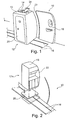
- Fig. 1 shows a perspective view of a section of the interior of a cabin 10 of an aircraft.
- a monument 12 is fastened to two upper fastening rails 14 as fastening elements and to two seat rails 16 with further fastening elements adjacent to a door 18 in the cabin 10.
- the seat rails 16 are laid in the floor 17 of the cabin 10 and connected to the fuselage of the aircraft.
- the monument 12 is a toilet monument that can be entered through a door 20 and whose rear wall 22 is adapted to the curvature of the cabin wall in such a way that no cavity is created behind it.
- the rails 14 at the top 15 of the monument 12 are terminals which are screwed for example by means of screws to a rigidly connected to the support structure of the aircraft support member 24.
- the mounting rails 14 form a flexible fastener for the monument 12, since the attachment point of the monument 12 by moving the terminals is variable or flexible.
- the monument 12 may be secured to the cab 10 in a range of relative positions in the aircraft's longitudinal direction L. The area is limited by the length of the rails 14. If the monument 12 to be fixed offset approximately to the relative position shown with the cabin, only the screws that connect the monument with the seat rails 16 and the support member 24 are released, then the monument 12 are moved to the new position and then the monument 12 are bolted to the seat rails 16 and the support member 24 again.
- Fig. 2 shows a further embodiment of a monument 12a, which is connectable via a bottom plate 26 with the seat rails 16. At its top 15, the monument 12a as well as the monument 12 from the Fig. 1 be connected to the cabin.
- the monument 12a can be screwed at any point within the cabin with the seat rails 16.
- the bottom plate 26 distributes the weight of the monument 12 a such that a separate support structure for the monument 12 a in the floor 17 of the cabin 10 next to the support structure for the floor 17 can be dispensed with.
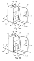
- Fig. 3a shows the monument 12a from the Fig. 2 with an alternative embodiment of a bottom plate 26a, which may be, for example, a kitchen monument, that is a so-called galley.
- a bottom plate 26a which may be, for example, a kitchen monument, that is a so-called galley.
- the monument 12a there are three receiving areas 28 for each one trolley 30.
- the trolley 30 can be moved in and out of the receiving areas 28.
- Fig. 3b shows a further embodiment of a monument 12b with integrated bottom plate 26b.
- the bottom plate 26b simultaneously provides the bottom of the receptacle 28a.
- the receptacle 28a has a door 34, which is shown open, so that can be seen in the interior of the receptacle 28a.
- the wedge-shaped portion 32a of the bottom plate 26b serving as a ramp is disposed inside the receptacle 28a.
- the bottom plate 26b has the same base as the monument 12b.
- the bottom plate 26 a of the wedge-shaped portion 32 projects beyond the base of the monument 12 a.
- the bottom plate 26a therefore has a greater extent than the base of the monument 12a.
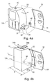
- Fig. 4a shows the monument 12b according to the invention with a supply connection 36 whose connection end 38 is movable relative to the monument.
- the connection end 38 is movable in the horizontal direction.
- the supply connection 36 comprises a plurality of tubes, which are arranged movably in the interior of the monument such that the connection end 38 can be displaced according to the invention along the opening 37.
- the Terminal end 38 is connectable via a terminal end 40 to an onboard system or multiple onboard systems of the aircraft.
- the monument 12b could be a kitchen monument, which is supplied with hot and cold water via the supply connection 36, and gray water can be conducted back to the wastewater system of the aircraft via the supply connection 36.
- That in the Fig. 4a illustrated Monument 12b has on its upper side a fastener 42.
- the monument can just as one of the previous monuments by means of the seat rails 16 are connected to the aircraft.
- Fig. 4b shows a further embodiment of a monument 12c with a single mounting rail 14a at its top 15.
- the mounting rail 14a for example, with the aid of a clamp located in it to a support member 24a, which is rigidly connected to the fuselage of the aircraft, attached.
- the monument 12c further includes a supply terminal having a terminal end 38 which can be moved in a horizontal direction relative to the monument and which can be connected to a terminal end 40 with at least one on-board system of the aircraft.
- the monument 12 c can be attached to a range of relative positions R inside the cabin 10.
- R the range of relative positions R inside the cabin 10.
- the element 12c With released fasteners, the element 12c can be moved within the area R.
- the area R is limited by the length of the mounting rail 14a and the possible range of movement of the terminal end 38.
- the terminal end 40 of the aircraft is located at a fixed location within the cabin, it is not necessary to route conduits or pipes to the monument 12c as the terminal end 38 can be displaced relative to the monument 12c.
- the monument 12 c can be moved from the illustrated center position up to 30 cm in the direction L of the aircraft longitudinal axis, without an extension from the terminal end 40 to the movable end 38 is necessary.
- Fig. 5 1 schematically shows how an embodiment of a monument 12d can be supplied with power by means of induction loops 42, 44.
- a first induction loop 44 is arranged, which is connected to the power supply system of the aircraft.
- a second induction loop 42 in which current is induced by means of the induction principle through the first induction loop 44, which current can be supplied to a load 46, such as a lamp.
- the Fig. 6 shows a further embodiment of a monument 12e, which is fastened on the one hand by means of the seat rails 16 at the bottom of the cabin 10 and on the other hand has fastening elements 50 which can be fastened to a mounting rail 48 for a storage compartment.
- the fasteners 50 can be secured in elongated openings 51 of the mounting rail 48.
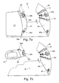
- the Fig. 7a shows another embodiment of a monument 12f, the fastening elements 50, a first supply terminal 36a and a second supply terminal 36b has.
- the fasteners 50 are connectable to a mounting rail 48 for storage compartments.
- the first supply terminal 36a has a terminal end 38a connectable to a terminal end 40a of the aircraft.
- the supply connection 36a could be, for example, a plurality of pipes or hoses with which the monument 12f can be supplied with service water and with which gray or black water produced in the monument 12f can be returned to the aircraft.
- the second supply port 36b has a connection end 38b which can be connected to other on-board systems via a connection end 40b of the aircraft.
- the power supply of the monument 12f and a data network connection could be integrated into the supply port 36b.
- the connection ends 36a and 36b are movable in a horizontal direction relative to the monument 12f. If the monument 12f is to be connected to the car 10, the monument 12f is first roughly pushed to its target position. Then, the terminal ends 38a and 38b are connected to the corresponding terminal ends 40a and 40b.
- the monument 12f can be moved exactly to its target position, with the connection ends 38a and 38b of the monument 12f, which are now firmly connected to the connection ends 40a and 40b, moving relative to the monument 12f.
- the fasteners 50 are connected to the mounting rail 48, for example, by being screwed by means of screws through the elongated openings 51 on mounting rail 48.
- the Fig. 7b shows an embodiment of a storage compartment 52 in the form of a luggage rack.
- the storage compartment 52 has a supply terminal 36c with terminal end 38c, which is immovably connected to the storage compartment 52.
- the storage compartment 52 can be suspended in the elongated openings 51 in the fastening rail 48.
- the connection end 38c can be connected to the connection end 40b.
- the storage compartment 52 is supported in the fastened position with the rear portion 56 on the mounting rail 54 from.
- a plurality of terminal ends 40 b are attached in the side wall 58 of the cabin 10.
- a connection end 40b is provided for each storage compartment 52.
- the terminal ends 40b are arranged at equal intervals in the direction of the longitudinal direction L of the aircraft.
- the terminal ends 40b are spaced apart by the length of consecutive storage compartments 52.
- the location of the storage compartments 52 is determined by the location of the terminal ends 40b, the position of the monument 12f with respect to a longitudinal direction L of the aircraft can be freely selected when the horizontal mobility of the terminal ends 36a and 36b is greater than the distance of the terminal ends 40b.
- FIG. 7a and 7b an installation system for an aircraft is shown, which comprises one or more of the monuments 12f and one or more of the storage compartments 52.
- the Fig. 8a shows another installation system for an aircraft, which includes the monument 12g and two storage compartments 52a and 52b.
- the monument 12g may be attached to the cabin 10 and connected to the on-board systems of the aircraft.
- the storage compartments 52a and 52b can also be fastened to a fastening rail 48 on the cabin and have a supply connection 36c.
- the storage compartments 52a and 52b have a different length in the direction of the aircraft's longitudinal axis. In this way, it can be avoided that, when the monument 12g is arranged at a distance to the storage compartment 52a, which is shorter than the length of the storage compartment 52a, a gap is created. For closing gaps of different lengths, storage compartments 52b of different lengths are provided.
- a storage compartment 52c comprising two telescopically telescoping elements 60 and 62.
- a gap that would arise between the storage compartment 52a and the monument 12g can be closed, in which the element 62 is pulled out of the element 60. This can be done automatically, for example, by means of pneumatic springs.
- the Fig. 9a shows the storage compartment 52c in cross-section, which includes the two elements 60c and 62c.
- the element 62c can be pushed into the element 60c.
- an OLED 64c, 66c is attached to the underside thereof.
- the element 62c may be supported on one side on a monument 12.
- the Fig. 9b shows the storage compartment 52c, in which the elements are pushed closer together than in the Fig. 9a , The OLED 66c is partially pushed into the interior of the element 64c. The OLEDs 64c and 66c overlap.
- the Fig. 9c and 9d show a telescopically collapsible storage compartment 52d essentially like the storage compartment of the Fig. 9a and 9b is constructed.
- the OLED 66d is flush mounted to the OLED 64d or at the same height as this one. When pushed together, the OLED 66d is folded and moves parallel to the side surface 61 d of the element 60d into the element 62d.
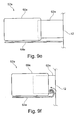
- the Figs. 9e and 9f show a telescopically collapsible storage compartment 52e essentially as the storage compartments from the Fig. 9a to 9d is constructed.
- the storage compartment 52 has a single OLED 64e attached to the element 60e. When the elements 60e and 62e are pushed together, the OLED 64e is rolled into the interior of the element 62e.
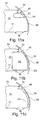
- the Fig. 10 shows a portion of a cabin 10 of an aircraft.
- the monuments 12h and 12i may be connected to the cabin and / or the on-board systems of the aircraft.
- the monument 12h has a rear wall 22h which is curved such that between the rear wall 22h and the side cover 66h in the in the Fig. 10 As shown in the arrangement position of the monument 12h, a large cavity is not formed between the back wall 22h of the monument 12h and the side trim 66h of the aircraft cabin 10. If the monument 12h is moved counter to the arrow L for the aircraft longitudinal direction, exists between Monument 12h and side panel 66h a cavity that is not visible from the outside.
- the monument 12i also has a rear wall 22i which is curved in such a way that substantially no hollow space is created between the rear wall 22i and the side wall 66i in a specific position of the monument 12i.
- the monument 12i is arranged such that a window 68 in the side wall 66i is not obscured by the monument 12i. Therefore, a cavity is created between the monument 12i and the side cover 66i. This cavity can be closed by a compensation element 70 to the window 68. Also from the compensation element 70 is in the Fig. 10 only the base area shown.
- the Fig. 11a shows a cross section through a cabin 10 of an aircraft.
- the cabin is bounded from below by a bottom 17, are mounted in the seat rails 16. Laterally, the cabin 10 is bounded by a side wall 58, to which mounting rails 48, 54 are located, to which a storage compartment 52 is attached, approximately as it is in the Fig. 7b is shown.
- the cabin 10 is bounded above by a ceiling panel 70 which is connected via its own fasteners 72 to the side wall 58 of the cabin.
- the storage compartment 52 can be removed from the wall 58 without having to remove the ceiling panel 70.
- Fig. 11b is a to Fig. 11a represented analog cross section through a cabin 10 of an aircraft.
- a monument 12j is connected to the cabin 10. This could be done by means of the mounting rail 48 and the seat rails 16 as shown in the preceding figures.
- the monument 12j can be mounted in the cabin without having to dislodge the ceiling panel 70, since the monument 12j and the ceiling panel 70 have their own separate fasteners 48, 72 with the wall 58.
- the monument 12j fills the space between the floor 17 and the ceiling panel 70 so that there are no large gaps through which the wall 58 of the cabin 10 would be visible. In this way, further cladding elements are avoided.
- the Fig. 11c shows a cross section through a cabin 10 of an aircraft analogous to Fig. 11a and 11b ,
- a side trim 74 is connected to the wall 58 of the cabin 10. This could, for example, as in the Fig. 11 indicated, via the mounting rail 54 or also via the mounting rail 48 done.
- the side trim 74 runs from the floor 17 of the cabin 10 to the ceiling trim 70.
- FIG. 11a to 11c illustrated installation system makes it possible to exchange storage compartments 52, monuments 12j and side panels 74 as desired, without the ceiling panel 70 would have to be removed.
- Fig. 12 shows a schematic plan view of an aircraft 100 with several monuments 14, which are mounted in a cabin 110.
Landscapes
- Engineering & Computer Science (AREA)
- Mechanical Engineering (AREA)
- Aviation & Aerospace Engineering (AREA)
- Public Health (AREA)
- Epidemiology (AREA)
- General Health & Medical Sciences (AREA)
- Health & Medical Sciences (AREA)
- Tents Or Canopies (AREA)
- Residential Or Office Buildings (AREA)
- Packaging Of Machine Parts And Wound Products (AREA)
- Vehicle Waterproofing, Decoration, And Sanitation Devices (AREA)
- Warehouses Or Storage Devices (AREA)
- Vehicle Step Arrangements And Article Storage (AREA)
Claims (13)
- Structure (12) pour une cabine (10) d'un moyen de transport, comprenant :- un élément de fixation pour la fixation de la structure (12) à la cabine (10) du moyen de transport,- au moins un raccord d'alimentation (36, 36a, 36b) pour raccorder la structure à au moins un système de bord du moyen de transport,l'élément de fixation étant configuré de telle sorte que la fixation de la structure (12) puisse être réalisée dans une plage de positions relatives (R) de la structure (12) par rapport à la cabine (10) du moyen de transport,
l'élément de fixation pouvant être relié à un rail de siège (16) du moyen de transport, le raccord d'alimentation présentant une extrémité de raccord de la structure (38, 38a, 3 8b), qui peut être raccordée à une extrémité de raccord du moyen de transport (40, 40a, 40b) du système de bord,
l'extrémité de raccord de la structure (38, 38a, 38b) étant mobile par rapport à la structure, l'extrémité de raccord de la structure pouvant être déplacée le long d'une ouverture de la structure. - Structure (12f) selon la revendication 1, l'élément de fixation pouvant être relié à un rail de fixation (48) pour un compartiment de rangement (52).
- Structure (12) selon l'une des revendications précédentes, l'élément de fixation comprenant un rail de fixation (14).
- Structure (12a, 12b) selon l'une des revendications précédentes, comprenant en outre :- des éléments de fixation pour la fixation de la structure à un plancher (17) de la cabine, et- une infrastructure (26a, 26b) répartissant une charge, l'infrastructure (26a, 26b) répartissant la charge étant adaptée à une répartition uniforme des forces exercées par la structure sur les éléments de fixation et le plancher (17).
- Structure (12a, 12b) selon la revendication 4, comprenant en outre :- un chariot de transport (30),- une zone de réception (28) pour le chariot de transport,le chariot de transport pouvant être inséré dans et retiré de la zone de réception, l'infrastructure répartissant la charge comprenant une plaque de base (26a, 26b), et la plaque de base (26a, 26b) comprenant une section (32, 32a) en forme de coin, servant de rampe pour le chariot de transport dans la zone de réception.
- Structure (12f) selon la revendication 1, l'extrémité de raccord de la structure (38b) pouvant être raccordée à une extrémité de raccord du moyen de transport (40b), qui est adaptée au raccordement à une extrémité de raccord du compartiment de rangement (38c).
- Structure (12d) selon l'une des revendications précédentes, comprenant en outre :- une boucle d'induction (42), par laquelle la structure peut être alimentée en courant avec une boucle d'induction (44) du moyen de transport.
- Système d'installation pour l'installation dans un moyen de transport, comprenant :- une structure selon l'une des revendications 1 à 7.
- Système d'installation pour un moyen de transport selon la revendication 8, comprenant en outre :- au moins deux compartiments de rangement (52a, 52b), dont l'extension dans la direction longitudinale du moyen de transport se distingue l'une de l'autre, et/ou- un compartiment de rangement (52c) dont l'extension peut être réglée dans la direction longitudinale du moyen de transport.
- Système d'installation selon l'une des revendications 8 ou 9, comprenant en outre :- un élément compensateur (70) adapté à remplir au moins partiellement une cavité apparaissant entre la structure (12i) et un habillage latéral (66i) du moyen de transport.
- Système d'installation selon l'une des revendications 8 à 10, comprenant en outre :- un habillage de plafond (70) pour la cabine (10) du moyen de transport, l'habillage de plafond (70) pouvant être raccordé via des premiers éléments de fixation (72) à la cabine (10),la structure (12j) pouvant être raccordé via deux éléments de fixation (48) à la cabine,
la structure pouvant limiter la cabine entre un plancher (17) de la cabine et l'habillage de plafond (70). - Système d'installation selon la revendication 11, comprenant en outre :- un habillage latéral (74) pour la cabine (10) du moyen de transport, l'habillage latéral (74) pouvant limiter la cabine entre le plancher (17) de la cabine et l'habillage de plafond (70),la structure (12j) et l'habillage latéral (74) pouvant être fixés aux mêmes points de fixation dans le moyen de transport.
- Moyen de transport, en particulier un aéronef ou un avion, avec une structure selon l'une des revendications 1 à 7 ou un système d'installation selon l'une des revendications 8 à 12.
Applications Claiming Priority (3)
| Application Number | Priority Date | Filing Date | Title |
|---|---|---|---|
| US16279109P | 2009-03-24 | 2009-03-24 | |
| DE102009014598A DE102009014598A1 (de) | 2009-03-24 | 2009-03-24 | Konfektionierbare Monumente |
| PCT/EP2010/052934 WO2010108775A2 (fr) | 2009-03-24 | 2010-03-09 | Unités modulaires aménageables |
Publications (2)
| Publication Number | Publication Date |
|---|---|
| EP2411273A2 EP2411273A2 (fr) | 2012-02-01 |
| EP2411273B1 true EP2411273B1 (fr) | 2013-03-06 |
Family
ID=42663996
Family Applications (1)
| Application Number | Title | Priority Date | Filing Date |
|---|---|---|---|
| EP10708520A Not-in-force EP2411273B1 (fr) | 2009-03-24 | 2010-03-09 | Unites modulaires amenageables |
Country Status (4)
| Country | Link |
|---|---|
| US (1) | US9016626B2 (fr) |
| EP (1) | EP2411273B1 (fr) |
| DE (1) | DE102009014598A1 (fr) |
| WO (1) | WO2010108775A2 (fr) |
Cited By (1)
| Publication number | Priority date | Publication date | Assignee | Title |
|---|---|---|---|---|
| EP3037350A1 (fr) | 2014-12-23 | 2016-06-29 | Airbus Operations GmbH | Agencement de toilettes pour une cabine de véhicule et véhicule comprenant une carrosserie de véhicule et une cabine ayant un agencement de toilettes installé dans celui-ci |
Families Citing this family (40)
| Publication number | Priority date | Publication date | Assignee | Title |
|---|---|---|---|---|
| EP1803645B1 (fr) * | 2005-12-29 | 2020-03-11 | Airbus Operations GmbH | Module pour un aéronef |
| DE102009014598A1 (de) | 2009-03-24 | 2010-09-30 | Airbus Deutschland Gmbh | Konfektionierbare Monumente |
| DE102009043314B4 (de) | 2009-09-28 | 2018-12-20 | Airbus Operations Gmbh | Kabinenausstattungskomponentenanschlusssystem und Verfahren zur Modifikation einer Passagierkabinenkonfiguration |
| DE102009053584A1 (de) * | 2009-11-17 | 2011-05-19 | Airbus Operations Gmbh | Trägersystem zum Aufnehmen von Behältern in einem Fahrzeug und Verwendung eines Trägersystems in einem Flugzeug |
| DE102011110010A1 (de) * | 2011-08-11 | 2013-02-14 | Airbus Operations Gmbh | Passagierversorgungsmodul mit integrierter Kabinenbeleuchtung |
| EP2818412B1 (fr) * | 2012-02-23 | 2020-05-20 | The Yokohama Rubber Co., Ltd. | Procédé d'installation d'unité de toilettes d'avion et avion |
| JP5849855B2 (ja) | 2012-05-11 | 2016-02-03 | 横浜ゴム株式会社 | 航空機用化粧室ユニットおよびその配置構造 |
| EP2695812A1 (fr) * | 2012-08-07 | 2014-02-12 | Airbus Operations GmbH | Architecture de système hybride eaux résiduaires/eau |
| US9038945B2 (en) * | 2013-03-15 | 2015-05-26 | B/E Aerospace, Inc. | Integrated aircraft galley system |
| USD730804S1 (en) * | 2013-05-29 | 2015-06-02 | The Boeing Company | Aircraft passageway storage unit |
| US9321533B2 (en) * | 2013-05-29 | 2016-04-26 | The Boeing Company | Aircraft passageway storage units |
| US9352837B2 (en) * | 2013-06-18 | 2016-05-31 | B/E Aerospace, Inc. | Aircraft galley with appliance inserts |
| EP2848526B1 (fr) * | 2013-09-11 | 2016-11-30 | Airbus Operations GmbH | Monument de partition dans cabine d'aronef avec compartiment de rangement et procedé |
| DE102013112019A1 (de) | 2013-10-31 | 2015-04-30 | Airbus Operations Gmbh | Stauschrank für ein Transportmittel |
| DE102014115747A1 (de) * | 2014-10-29 | 2016-05-04 | Airbus Operations Gmbh | Modulares Monument zum Befördern eines Transportgutes in einem Fahrzeug |
| EP3212500B1 (fr) * | 2014-10-31 | 2019-05-29 | C&D Zodiac, Inc. | Système d'installation pour ensemble monument d'aéronef arrière |
| EP3075650A1 (fr) * | 2015-03-30 | 2016-10-05 | Airbus Operations GmbH | Ensemble monument autoportant de grande taille pour aéronef et aéronef comportant un tel ensemble |
| DE102015206707A1 (de) | 2015-04-15 | 2016-10-20 | Airbus Operations Gmbh | Monument für eine Kabine eines Fahrzeugs und Befestigungsanordnung |
| DE102015206713A1 (de) | 2015-04-15 | 2016-10-20 | Airbus Operations Gmbh | Bausatz und Verfahren für einen Gehäuseaufbau eines Monuments für eine Fahrzeugkabine |
| US10322806B2 (en) * | 2016-01-04 | 2019-06-18 | The Boeing Company | Sliding closet |
| DE102016207607A1 (de) * | 2016-05-03 | 2017-11-09 | Airbus Operations Gmbh | Erweiterbares Flugzeugmonument und Flugzeugbereich mit einem erweiterbaren Flugzeugmonument |
| USD837348S1 (en) * | 2016-05-18 | 2019-01-01 | Bombardier Inc. | Aircraft lavatory cabinet |
| DE102017202068A1 (de) * | 2017-02-09 | 2018-08-09 | Airbus Operations Gmbh | Kabinenmonument für ein Luftfahrzeug |
| DE102017111913A1 (de) * | 2017-05-31 | 2018-12-06 | Airbus Operations Gmbh | Monumentenanordnung in einer Kabine eines Fahrzeugs, eine Kabine eines Fahrzeugs sowie ein Fahrzeug mit einer derartigen Kabine |
| DE102017116824A1 (de) | 2017-07-25 | 2019-01-31 | Airbus Operations Gmbh | Befestigungssystem zum Befestigen von Einrichtungsgegenständen an einem Fußboden einer Kabine eines Fahrzeugs |
| DE102017131130B4 (de) * | 2017-12-22 | 2023-05-04 | Airbus Operations Gmbh | Befestigungssystem zum Befestigen einer Komponente an einer Rumpfstruktur |
| US11124299B2 (en) * | 2018-04-10 | 2021-09-21 | Rockwell Collins, Inc. | Multi-mode transformable monuments for aircraft doorway spaces |
| US11919643B2 (en) * | 2018-04-10 | 2024-03-05 | Rockwell Collins, Inc. | Self-deploying counter for multimode transformable monuments |
| CN110539766B (zh) * | 2018-06-25 | 2020-07-31 | 中车长春轨道客车股份有限公司 | 一种轨道车辆及其厨房设备吊装骨架 |
| US11377262B2 (en) * | 2018-11-09 | 2022-07-05 | Hamilton Sundstrand Corporation | Customizable integration system for pallet |
| DE102019107359A1 (de) | 2019-03-22 | 2020-09-24 | Airbus Operations Gmbh | Vielzweckanschluss für ein Flugzeugmonument sowie Flugzeugmonument, Flugzeugbereich und Flugzeug mit Vielzweckanschluss |
| US11407484B2 (en) | 2019-06-14 | 2022-08-09 | Airbus Americas, Inc. | Standard cabin monument sub-structure |
| US11465747B2 (en) * | 2019-07-31 | 2022-10-11 | The Boeing Company | Overhead support platform system for a vehicle |
| US11027846B2 (en) | 2019-08-27 | 2021-06-08 | B/E Aerospace, Inc. | Stowable door folding table |
| FR3106556B1 (fr) * | 2020-01-23 | 2022-02-11 | Speedinnov | Motrice ferroviaire avec dispositif de fixation d’équipement technique |
| US11572170B2 (en) * | 2020-07-21 | 2023-02-07 | B/E Aerospace, Inc. | Aircraft interior structure including actuatable panels and a footwell |
| US11529987B2 (en) * | 2020-10-05 | 2022-12-20 | B/E Aerospace, Inc. | Aircraft cart retention system |
| US20220388660A1 (en) * | 2021-06-04 | 2022-12-08 | The Boeing Company | Resting area systems for an internal cabin of a vehicle |
| US12559237B2 (en) * | 2023-05-24 | 2026-02-24 | The Boeing Company | Combination monument having lavatory and galley for an internal cabin of an aircraft |
| EP4603386A1 (fr) * | 2024-02-13 | 2025-08-20 | Airbus Operations GmbH | Système de retenue pour équipement de cabine |
Family Cites Families (20)
| Publication number | Priority date | Publication date | Assignee | Title |
|---|---|---|---|---|
| US5083727A (en) * | 1990-01-02 | 1992-01-28 | The Boeing Company | Aircraft cabin system for selectivley locating interior units |
| US5784836A (en) * | 1994-11-03 | 1998-07-28 | Be Aerospace, Inc. | Demountable comfort modules for passenger aircraft |
| DK171589B1 (da) * | 1996-01-19 | 1997-02-10 | Abb Daimler Benz Transp | Sanitetscelle |
| US6412603B1 (en) | 2000-07-21 | 2002-07-02 | The Boeing Company | Automated galley cart storage system |
| DE10161898C2 (de) * | 2001-10-06 | 2003-10-23 | Daimler Chrysler Ag | Variabel positionierbarer Fahrzeugsitz mit integrierten Personenrückhaltesystemen |
| WO2005012085A1 (fr) * | 2003-07-18 | 2005-02-10 | Telair International Gmbh | Plancher de compartiment a fret d'un aeronef et son procede de montage |
| EP1737095B1 (fr) * | 2005-06-22 | 2012-09-26 | Airbus Operations GmbH | Goulotte de puissance flexible |
| DE102005043610A1 (de) | 2005-09-13 | 2007-03-22 | Airbus Deutschland Gmbh | Modulares Monument |
| US20070102579A1 (en) | 2005-09-13 | 2007-05-10 | Airbus Deutschland Gmbh | Modular structure |
| DE102005054890B4 (de) * | 2005-11-17 | 2014-08-21 | Airbus Operations Gmbh | Flugzeugrumpfstruktur mit einer Passagierkabine und einer Befestigungsstruktur zur Fixierung von Inneneinrichtungskomponenten in der Passagierkabine |
| US7614583B2 (en) * | 2005-12-14 | 2009-11-10 | The Boeing Company | Monument fitting assembly |
| EP1803645B1 (fr) | 2005-12-29 | 2020-03-11 | Airbus Operations GmbH | Module pour un aéronef |
| DE102006048998A1 (de) * | 2005-12-29 | 2007-07-12 | Airbus Deutschland Gmbh | Teleskopartiges Gepäckfach |
| US8387918B2 (en) * | 2006-09-15 | 2013-03-05 | The Boeing Company | Multi-directional support arm |
| US8087611B2 (en) * | 2006-12-07 | 2012-01-03 | Be Aerospace, Inc. | Galley unit with cart lift for elevated cart storage |
| DE102007003802B4 (de) * | 2007-01-25 | 2008-10-23 | Airbus Deutschland Gmbh | Flexible Kabelanbindung an Monumente innerhalb einer Flugzeugkabine |
| DE102007017853B4 (de) * | 2007-04-16 | 2012-03-08 | Airbus Operations Gmbh | Mobile Trennwand für ein Luftfahrzeug |
| DE102007029677B4 (de) * | 2007-06-27 | 2012-03-15 | Mühlenberg Interiors Gmbh & Co. Kg | Verstausystem |
| DE102007030331A1 (de) * | 2007-06-29 | 2009-01-02 | Airbus Deutschland Gmbh | Staufachmodul für einen Innenraum eines Flugzeugs |
| DE102009014598A1 (de) | 2009-03-24 | 2010-09-30 | Airbus Deutschland Gmbh | Konfektionierbare Monumente |
-
2009
- 2009-03-24 DE DE102009014598A patent/DE102009014598A1/de not_active Withdrawn
-
2010
- 2010-03-09 WO PCT/EP2010/052934 patent/WO2010108775A2/fr not_active Ceased
- 2010-03-09 EP EP10708520A patent/EP2411273B1/fr not_active Not-in-force
-
2011
- 2011-09-24 US US13/244,437 patent/US9016626B2/en active Active
Cited By (2)
| Publication number | Priority date | Publication date | Assignee | Title |
|---|---|---|---|---|
| EP3037350A1 (fr) | 2014-12-23 | 2016-06-29 | Airbus Operations GmbH | Agencement de toilettes pour une cabine de véhicule et véhicule comprenant une carrosserie de véhicule et une cabine ayant un agencement de toilettes installé dans celui-ci |
| US10093420B2 (en) | 2014-12-23 | 2018-10-09 | Airbus Operations Gmbh | Lavatory arrangement for a vehicle cabin and vehicle having a vhicle body, and a cabin having a lavatory arrangement installed therein |
Also Published As
| Publication number | Publication date |
|---|---|
| US9016626B2 (en) | 2015-04-28 |
| DE102009014598A1 (de) | 2010-09-30 |
| WO2010108775A2 (fr) | 2010-09-30 |
| WO2010108775A4 (fr) | 2011-04-14 |
| US20120248245A1 (en) | 2012-10-04 |
| EP2411273A2 (fr) | 2012-02-01 |
| WO2010108775A3 (fr) | 2011-02-17 |
Similar Documents
| Publication | Publication Date | Title |
|---|---|---|
| EP2411273B1 (fr) | Unites modulaires amenageables | |
| EP1481894B1 (fr) | Canal comprenant des points d'arrimage pour cargaison | |
| DE69725542T3 (de) | Fluggastsitz, drehbar und veränderbar in ein Bett | |
| WO2010046276A2 (fr) | Système de cale multifonctionnelle | |
| EP2563653B1 (fr) | Système de rails, et procédé et système pour monter une pièce dans un avion | |
| EP2310259B1 (fr) | Prémontage et intégration de cabines d'avions | |
| WO2010057744A2 (fr) | Unité d'alimentation pour canaux d'alimentation flexibles | |
| DE102009023401B4 (de) | Halter zur Befestigung einer zur Montage in einem Flugzeugrumpfelement vorgesehenen Interieurkomponente an einer Transportvorrichtung sowie Transportvorrichtung | |
| EP0992428B1 (fr) | Passerelle déplaçable pour l'embarquement des avions | |
| DE202013100573U1 (de) | Fahrgestell | |
| DE102013110500A1 (de) | Vorrichtung zum Haltern eines Fahrzeugbegleitersitzes in einer Kabine eines Fahrzeugs, Kabinenanordnung in einem Fahrzeug und Fahrzeug mit mindestens einer Kabinenanordnung | |
| EP0035955A2 (fr) | Avion avec récipient de transport ou conteneur | |
| DE102018123531B4 (de) | Verfahren zum Installieren von Systemkomponenten in einem Abschnitt eines Flugzeugrumpfs | |
| DE102016104794A1 (de) | Trennwandmodul für eine Kabine eines Fahrzeugs zur optischen und mechanischen Abtrennung unterschiedlicher Kabinenbereiche | |
| DE102007015520A1 (de) | Unterbodensystem für ein Flugzeug | |
| EP1481893A2 (fr) | Système d'arrimage pour fret | |
| EP2722225B1 (fr) | Bâti d'un camping-car ou de véhicules similaires et châssis pour un tel bâti | |
| DE102006007027A1 (de) | Doppelwandiges Fußbodensegment für ein Fortbewegungsmittel zur Aufnahme von Systemkomponenten | |
| DE102006034862A1 (de) | Verfahren und Kabinenmodul zum Rekonfigurieren einer Fahrzeugkabine | |
| EP2868544B1 (fr) | Dispositif de fixation pour un profilé de transition dans un véhicule sur rail, composant pour un dispositif de fixation et procédé de fixation d'un profilé de transition | |
| DE102019132513A1 (de) | Bodenelement sowie Luftfahrzeugbereich und Luftfahrzeug mit einem Bodenelement | |
| DE19530035A1 (de) | Mechanische Parkeinrichtung mit hydraulischem Antrieb, so ausgestattet, daß mindestens zwei PKW's unabhängig voneinander waagrecht auf den Stellplätzen abgestellt werden können | |
| DE102010047385A1 (de) | Halterung für Inneneinrichtungskomponenten in Flugzeugkabinen | |
| DE102007009500B4 (de) | Mobile Verkleidung für einen Flugzeugrollcontainer | |
| DE102007062747B4 (de) | Bodenplatte zur Abdeckung eines Fußbodengerüstes in einem Flugzeug |
Legal Events
| Date | Code | Title | Description |
|---|---|---|---|
| PUAI | Public reference made under article 153(3) epc to a published international application that has entered the european phase |
Free format text: ORIGINAL CODE: 0009012 |
|
| 17P | Request for examination filed |
Effective date: 20110921 |
|
| AK | Designated contracting states |
Kind code of ref document: A2 Designated state(s): AT BE BG CH CY CZ DE DK EE ES FI FR GB GR HR HU IE IS IT LI LT LU LV MC MK MT NL NO PL PT RO SE SI SK SM TR |
|
| DAX | Request for extension of the european patent (deleted) | ||
| GRAJ | Information related to disapproval of communication of intention to grant by the applicant or resumption of examination proceedings by the epo deleted |
Free format text: ORIGINAL CODE: EPIDOSDIGR1 |
|
| GRAP | Despatch of communication of intention to grant a patent |
Free format text: ORIGINAL CODE: EPIDOSNIGR1 |
|
| GRAP | Despatch of communication of intention to grant a patent |
Free format text: ORIGINAL CODE: EPIDOSNIGR1 |
|
| GRAS | Grant fee paid |
Free format text: ORIGINAL CODE: EPIDOSNIGR3 |
|
| GRAA | (expected) grant |
Free format text: ORIGINAL CODE: 0009210 |
|
| AK | Designated contracting states |
Kind code of ref document: B1 Designated state(s): AT BE BG CH CY CZ DE DK EE ES FI FR GB GR HR HU IE IS IT LI LT LU LV MC MK MT NL NO PL PT RO SE SI SK SM TR |
|
| REG | Reference to a national code |
Ref country code: GB Ref legal event code: FG4D Free format text: NOT ENGLISH |
|
| REG | Reference to a national code |
Ref country code: CH Ref legal event code: EP Ref country code: AT Ref legal event code: REF Ref document number: 599446 Country of ref document: AT Kind code of ref document: T Effective date: 20130315 |
|
| REG | Reference to a national code |
Ref country code: IE Ref legal event code: FG4D Free format text: LANGUAGE OF EP DOCUMENT: GERMAN |
|
| REG | Reference to a national code |
Ref country code: DE Ref legal event code: R096 Ref document number: 502010002439 Country of ref document: DE Effective date: 20130502 |
|
| PG25 | Lapsed in a contracting state [announced via postgrant information from national office to epo] |
Ref country code: LT Free format text: LAPSE BECAUSE OF FAILURE TO SUBMIT A TRANSLATION OF THE DESCRIPTION OR TO PAY THE FEE WITHIN THE PRESCRIBED TIME-LIMIT Effective date: 20130306 Ref country code: BG Free format text: LAPSE BECAUSE OF FAILURE TO SUBMIT A TRANSLATION OF THE DESCRIPTION OR TO PAY THE FEE WITHIN THE PRESCRIBED TIME-LIMIT Effective date: 20130606 Ref country code: NO Free format text: LAPSE BECAUSE OF FAILURE TO SUBMIT A TRANSLATION OF THE DESCRIPTION OR TO PAY THE FEE WITHIN THE PRESCRIBED TIME-LIMIT Effective date: 20130606 Ref country code: ES Free format text: LAPSE BECAUSE OF FAILURE TO SUBMIT A TRANSLATION OF THE DESCRIPTION OR TO PAY THE FEE WITHIN THE PRESCRIBED TIME-LIMIT Effective date: 20130617 Ref country code: SE Free format text: LAPSE BECAUSE OF FAILURE TO SUBMIT A TRANSLATION OF THE DESCRIPTION OR TO PAY THE FEE WITHIN THE PRESCRIBED TIME-LIMIT Effective date: 20130306 |
|
| REG | Reference to a national code |
Ref country code: NL Ref legal event code: VDEP Effective date: 20130306 |
|
| REG | Reference to a national code |
Ref country code: LT Ref legal event code: MG4D |
|
| PG25 | Lapsed in a contracting state [announced via postgrant information from national office to epo] |
Ref country code: LV Free format text: LAPSE BECAUSE OF FAILURE TO SUBMIT A TRANSLATION OF THE DESCRIPTION OR TO PAY THE FEE WITHIN THE PRESCRIBED TIME-LIMIT Effective date: 20130306 Ref country code: GR Free format text: LAPSE BECAUSE OF FAILURE TO SUBMIT A TRANSLATION OF THE DESCRIPTION OR TO PAY THE FEE WITHIN THE PRESCRIBED TIME-LIMIT Effective date: 20130607 Ref country code: FI Free format text: LAPSE BECAUSE OF FAILURE TO SUBMIT A TRANSLATION OF THE DESCRIPTION OR TO PAY THE FEE WITHIN THE PRESCRIBED TIME-LIMIT Effective date: 20130306 Ref country code: SI Free format text: LAPSE BECAUSE OF FAILURE TO SUBMIT A TRANSLATION OF THE DESCRIPTION OR TO PAY THE FEE WITHIN THE PRESCRIBED TIME-LIMIT Effective date: 20130306 |
|
| BERE | Be: lapsed |
Owner name: AIRBUS OPERATIONS G.M.B.H. Effective date: 20130331 |
|
| PG25 | Lapsed in a contracting state [announced via postgrant information from national office to epo] |
Ref country code: HR Free format text: LAPSE BECAUSE OF FAILURE TO SUBMIT A TRANSLATION OF THE DESCRIPTION OR TO PAY THE FEE WITHIN THE PRESCRIBED TIME-LIMIT Effective date: 20130306 |
|
| PG25 | Lapsed in a contracting state [announced via postgrant information from national office to epo] |
Ref country code: EE Free format text: LAPSE BECAUSE OF FAILURE TO SUBMIT A TRANSLATION OF THE DESCRIPTION OR TO PAY THE FEE WITHIN THE PRESCRIBED TIME-LIMIT Effective date: 20130306 Ref country code: NL Free format text: LAPSE BECAUSE OF FAILURE TO SUBMIT A TRANSLATION OF THE DESCRIPTION OR TO PAY THE FEE WITHIN THE PRESCRIBED TIME-LIMIT Effective date: 20130306 Ref country code: IS Free format text: LAPSE BECAUSE OF FAILURE TO SUBMIT A TRANSLATION OF THE DESCRIPTION OR TO PAY THE FEE WITHIN THE PRESCRIBED TIME-LIMIT Effective date: 20130706 Ref country code: CZ Free format text: LAPSE BECAUSE OF FAILURE TO SUBMIT A TRANSLATION OF THE DESCRIPTION OR TO PAY THE FEE WITHIN THE PRESCRIBED TIME-LIMIT Effective date: 20130306 Ref country code: MC Free format text: LAPSE BECAUSE OF NON-PAYMENT OF DUE FEES Effective date: 20130331 Ref country code: SK Free format text: LAPSE BECAUSE OF FAILURE TO SUBMIT A TRANSLATION OF THE DESCRIPTION OR TO PAY THE FEE WITHIN THE PRESCRIBED TIME-LIMIT Effective date: 20130306 Ref country code: PT Free format text: LAPSE BECAUSE OF FAILURE TO SUBMIT A TRANSLATION OF THE DESCRIPTION OR TO PAY THE FEE WITHIN THE PRESCRIBED TIME-LIMIT Effective date: 20130708 Ref country code: RO Free format text: LAPSE BECAUSE OF FAILURE TO SUBMIT A TRANSLATION OF THE DESCRIPTION OR TO PAY THE FEE WITHIN THE PRESCRIBED TIME-LIMIT Effective date: 20130306 |
|
| PG25 | Lapsed in a contracting state [announced via postgrant information from national office to epo] |
Ref country code: PL Free format text: LAPSE BECAUSE OF FAILURE TO SUBMIT A TRANSLATION OF THE DESCRIPTION OR TO PAY THE FEE WITHIN THE PRESCRIBED TIME-LIMIT Effective date: 20130306 |
|
| REG | Reference to a national code |
Ref country code: IE Ref legal event code: MM4A |
|
| PLBE | No opposition filed within time limit |
Free format text: ORIGINAL CODE: 0009261 |
|
| STAA | Information on the status of an ep patent application or granted ep patent |
Free format text: STATUS: NO OPPOSITION FILED WITHIN TIME LIMIT |
|
| PG25 | Lapsed in a contracting state [announced via postgrant information from national office to epo] |
Ref country code: DK Free format text: LAPSE BECAUSE OF FAILURE TO SUBMIT A TRANSLATION OF THE DESCRIPTION OR TO PAY THE FEE WITHIN THE PRESCRIBED TIME-LIMIT Effective date: 20130306 Ref country code: IE Free format text: LAPSE BECAUSE OF NON-PAYMENT OF DUE FEES Effective date: 20130309 Ref country code: BE Free format text: LAPSE BECAUSE OF NON-PAYMENT OF DUE FEES Effective date: 20130331 |
|
| 26N | No opposition filed |
Effective date: 20131209 |
|
| PG25 | Lapsed in a contracting state [announced via postgrant information from national office to epo] |
Ref country code: IT Free format text: LAPSE BECAUSE OF FAILURE TO SUBMIT A TRANSLATION OF THE DESCRIPTION OR TO PAY THE FEE WITHIN THE PRESCRIBED TIME-LIMIT Effective date: 20130306 |
|
| REG | Reference to a national code |
Ref country code: DE Ref legal event code: R097 Ref document number: 502010002439 Country of ref document: DE Effective date: 20131209 |
|
| PG25 | Lapsed in a contracting state [announced via postgrant information from national office to epo] |
Ref country code: MT Free format text: LAPSE BECAUSE OF FAILURE TO SUBMIT A TRANSLATION OF THE DESCRIPTION OR TO PAY THE FEE WITHIN THE PRESCRIBED TIME-LIMIT Effective date: 20130306 |
|
| REG | Reference to a national code |
Ref country code: CH Ref legal event code: PL |
|
| PG25 | Lapsed in a contracting state [announced via postgrant information from national office to epo] |
Ref country code: CH Free format text: LAPSE BECAUSE OF NON-PAYMENT OF DUE FEES Effective date: 20140331 Ref country code: LI Free format text: LAPSE BECAUSE OF NON-PAYMENT OF DUE FEES Effective date: 20140331 |
|
| PG25 | Lapsed in a contracting state [announced via postgrant information from national office to epo] |
Ref country code: SM Free format text: LAPSE BECAUSE OF FAILURE TO SUBMIT A TRANSLATION OF THE DESCRIPTION OR TO PAY THE FEE WITHIN THE PRESCRIBED TIME-LIMIT Effective date: 20130306 |
|
| PG25 | Lapsed in a contracting state [announced via postgrant information from national office to epo] |
Ref country code: CY Free format text: LAPSE BECAUSE OF FAILURE TO SUBMIT A TRANSLATION OF THE DESCRIPTION OR TO PAY THE FEE WITHIN THE PRESCRIBED TIME-LIMIT Effective date: 20130306 Ref country code: TR Free format text: LAPSE BECAUSE OF FAILURE TO SUBMIT A TRANSLATION OF THE DESCRIPTION OR TO PAY THE FEE WITHIN THE PRESCRIBED TIME-LIMIT Effective date: 20130306 |
|
| PG25 | Lapsed in a contracting state [announced via postgrant information from national office to epo] |
Ref country code: MK Free format text: LAPSE BECAUSE OF FAILURE TO SUBMIT A TRANSLATION OF THE DESCRIPTION OR TO PAY THE FEE WITHIN THE PRESCRIBED TIME-LIMIT Effective date: 20130306 Ref country code: LU Free format text: LAPSE BECAUSE OF NON-PAYMENT OF DUE FEES Effective date: 20130309 Ref country code: HU Free format text: LAPSE BECAUSE OF FAILURE TO SUBMIT A TRANSLATION OF THE DESCRIPTION OR TO PAY THE FEE WITHIN THE PRESCRIBED TIME-LIMIT; INVALID AB INITIO Effective date: 20100309 |
|
| REG | Reference to a national code |
Ref country code: FR Ref legal event code: PLFP Year of fee payment: 7 |
|
| REG | Reference to a national code |
Ref country code: DE Ref legal event code: R082 Ref document number: 502010002439 Country of ref document: DE Representative=s name: LKGLOBAL | LORENZ & KOPF PARTG MBB PATENTANWAE, DE Ref country code: DE Ref legal event code: R082 Ref document number: 502010002439 Country of ref document: DE Representative=s name: KOPF WESTENBERGER WACHENHAUSEN PATENTANWAELTE , DE Ref country code: DE Ref legal event code: R082 Ref document number: 502010002439 Country of ref document: DE Representative=s name: LKGLOBAL LORENZ UND KOPF PATENTANWALT, ATTORNE, DE |
|
| REG | Reference to a national code |
Ref country code: AT Ref legal event code: MM01 Ref document number: 599446 Country of ref document: AT Kind code of ref document: T Effective date: 20150309 |
|
| PGFP | Annual fee paid to national office [announced via postgrant information from national office to epo] |
Ref country code: GB Payment date: 20160321 Year of fee payment: 7 |
|
| PG25 | Lapsed in a contracting state [announced via postgrant information from national office to epo] |
Ref country code: AT Free format text: LAPSE BECAUSE OF NON-PAYMENT OF DUE FEES Effective date: 20150309 |
|
| REG | Reference to a national code |
Ref country code: FR Ref legal event code: PLFP Year of fee payment: 8 |
|
| GBPC | Gb: european patent ceased through non-payment of renewal fee |
Effective date: 20170309 |
|
| PG25 | Lapsed in a contracting state [announced via postgrant information from national office to epo] |
Ref country code: GB Free format text: LAPSE BECAUSE OF NON-PAYMENT OF DUE FEES Effective date: 20170309 |
|
| REG | Reference to a national code |
Ref country code: FR Ref legal event code: PLFP Year of fee payment: 9 |
|
| PGFP | Annual fee paid to national office [announced via postgrant information from national office to epo] |
Ref country code: DE Payment date: 20240320 Year of fee payment: 15 |
|
| PGFP | Annual fee paid to national office [announced via postgrant information from national office to epo] |
Ref country code: FR Payment date: 20240327 Year of fee payment: 15 |
|
| REG | Reference to a national code |
Ref country code: DE Ref legal event code: R119 Ref document number: 502010002439 Country of ref document: DE |
|
| PG25 | Lapsed in a contracting state [announced via postgrant information from national office to epo] |
Ref country code: DE Free format text: LAPSE BECAUSE OF NON-PAYMENT OF DUE FEES Effective date: 20251001 |
|
| PG25 | Lapsed in a contracting state [announced via postgrant information from national office to epo] |
Ref country code: FR Free format text: LAPSE BECAUSE OF NON-PAYMENT OF DUE FEES Effective date: 20250331 |