EP2412331A1 - Vorrichtung zum Messen einer von einem Femur auf eine Tibia ausgeführten Anstrengung im Hinblick auf die Implantation einer Gelenkprothese - Google Patents
Vorrichtung zum Messen einer von einem Femur auf eine Tibia ausgeführten Anstrengung im Hinblick auf die Implantation einer Gelenkprothese Download PDFInfo
- Publication number
- EP2412331A1 EP2412331A1 EP11174357A EP11174357A EP2412331A1 EP 2412331 A1 EP2412331 A1 EP 2412331A1 EP 11174357 A EP11174357 A EP 11174357A EP 11174357 A EP11174357 A EP 11174357A EP 2412331 A1 EP2412331 A1 EP 2412331A1
- Authority
- EP
- European Patent Office
- Prior art keywords
- branches
- femur
- tibia
- face
- substrate
- Prior art date
- Legal status (The legal status is an assumption and is not a legal conclusion. Google has not performed a legal analysis and makes no representation as to the accuracy of the status listed.)
- Withdrawn
Links
- 210000000689 upper leg Anatomy 0.000 title claims abstract description 37
- 210000002303 tibia Anatomy 0.000 title claims description 39
- 239000000758 substrate Substances 0.000 claims abstract description 25
- OKTJSMMVPCPJKN-UHFFFAOYSA-N Carbon Chemical compound [C] OKTJSMMVPCPJKN-UHFFFAOYSA-N 0.000 claims description 2
- 229910052799 carbon Inorganic materials 0.000 claims description 2
- 239000006260 foam Substances 0.000 claims description 2
- 239000002245 particle Substances 0.000 claims description 2
- 229920001296 polysiloxane Polymers 0.000 claims description 2
- 239000000463 material Substances 0.000 claims 1
- 239000004020 conductor Substances 0.000 abstract description 4
- 210000003127 knee Anatomy 0.000 description 7
- 235000021183 entrée Nutrition 0.000 description 5
- 210000000629 knee joint Anatomy 0.000 description 5
- 239000012530 fluid Substances 0.000 description 4
- 238000005259 measurement Methods 0.000 description 4
- 210000003484 anatomy Anatomy 0.000 description 1
- 239000012141 concentrate Substances 0.000 description 1
- 238000007796 conventional method Methods 0.000 description 1
- 238000006073 displacement reaction Methods 0.000 description 1
- 238000005530 etching Methods 0.000 description 1
- 238000003780 insertion Methods 0.000 description 1
- 230000037431 insertion Effects 0.000 description 1
- 239000011810 insulating material Substances 0.000 description 1
- 210000003041 ligament Anatomy 0.000 description 1
- 238000012545 processing Methods 0.000 description 1
- 210000001519 tissue Anatomy 0.000 description 1
Images

Classifications
-
- A—HUMAN NECESSITIES
- A61—MEDICAL OR VETERINARY SCIENCE; HYGIENE
- A61B—DIAGNOSIS; SURGERY; IDENTIFICATION
- A61B90/00—Instruments, implements or accessories specially adapted for surgery or diagnosis and not covered by any of the groups A61B1/00 - A61B50/00, e.g. for luxation treatment or for protecting wound edges
- A61B90/06—Measuring instruments not otherwise provided for
-
- A—HUMAN NECESSITIES
- A61—MEDICAL OR VETERINARY SCIENCE; HYGIENE
- A61F—FILTERS IMPLANTABLE INTO BLOOD VESSELS; PROSTHESES; DEVICES PROVIDING PATENCY TO, OR PREVENTING COLLAPSING OF, TUBULAR STRUCTURES OF THE BODY, e.g. STENTS; ORTHOPAEDIC, NURSING OR CONTRACEPTIVE DEVICES; FOMENTATION; TREATMENT OR PROTECTION OF EYES OR EARS; BANDAGES, DRESSINGS OR ABSORBENT PADS; FIRST-AID KITS
- A61F2/00—Filters implantable into blood vessels; Prostheses, i.e. artificial substitutes or replacements for parts of the body; Appliances for connecting them with the body; Devices providing patency to, or preventing collapsing of, tubular structures of the body, e.g. stents
- A61F2/02—Prostheses implantable into the body
- A61F2/30—Joints
- A61F2/46—Special tools for implanting artificial joints
- A61F2/4657—Measuring instruments used for implanting artificial joints
-
- A—HUMAN NECESSITIES
- A61—MEDICAL OR VETERINARY SCIENCE; HYGIENE
- A61B—DIAGNOSIS; SURGERY; IDENTIFICATION
- A61B90/00—Instruments, implements or accessories specially adapted for surgery or diagnosis and not covered by any of the groups A61B1/00 - A61B50/00, e.g. for luxation treatment or for protecting wound edges
- A61B90/06—Measuring instruments not otherwise provided for
- A61B2090/064—Measuring instruments not otherwise provided for for measuring force, pressure or mechanical tension
-
- A—HUMAN NECESSITIES
- A61—MEDICAL OR VETERINARY SCIENCE; HYGIENE
- A61F—FILTERS IMPLANTABLE INTO BLOOD VESSELS; PROSTHESES; DEVICES PROVIDING PATENCY TO, OR PREVENTING COLLAPSING OF, TUBULAR STRUCTURES OF THE BODY, e.g. STENTS; ORTHOPAEDIC, NURSING OR CONTRACEPTIVE DEVICES; FOMENTATION; TREATMENT OR PROTECTION OF EYES OR EARS; BANDAGES, DRESSINGS OR ABSORBENT PADS; FIRST-AID KITS
- A61F2/00—Filters implantable into blood vessels; Prostheses, i.e. artificial substitutes or replacements for parts of the body; Appliances for connecting them with the body; Devices providing patency to, or preventing collapsing of, tubular structures of the body, e.g. stents
- A61F2/02—Prostheses implantable into the body
- A61F2/30—Joints
- A61F2/38—Joints for elbows or knees
-
- A—HUMAN NECESSITIES
- A61—MEDICAL OR VETERINARY SCIENCE; HYGIENE
- A61F—FILTERS IMPLANTABLE INTO BLOOD VESSELS; PROSTHESES; DEVICES PROVIDING PATENCY TO, OR PREVENTING COLLAPSING OF, TUBULAR STRUCTURES OF THE BODY, e.g. STENTS; ORTHOPAEDIC, NURSING OR CONTRACEPTIVE DEVICES; FOMENTATION; TREATMENT OR PROTECTION OF EYES OR EARS; BANDAGES, DRESSINGS OR ABSORBENT PADS; FIRST-AID KITS
- A61F2/00—Filters implantable into blood vessels; Prostheses, i.e. artificial substitutes or replacements for parts of the body; Appliances for connecting them with the body; Devices providing patency to, or preventing collapsing of, tubular structures of the body, e.g. stents
- A61F2/02—Prostheses implantable into the body
- A61F2/30—Joints
- A61F2/46—Special tools for implanting artificial joints
- A61F2/4657—Measuring instruments used for implanting artificial joints
- A61F2002/4666—Measuring instruments used for implanting artificial joints for measuring force, pressure or mechanical tension
Definitions
- the invention relates to a device for measuring a force exerted by a femur on a tibia with a view to fitting a joint prosthesis.
- the surgeon performs, at the knee joint, a section of the femur and a cut of the tibia using a cutting guide. The surgeon then intercuts a prosthesis between the cut parts of the femur and tibia. The surgeon must ensure that said prosthesis respects both the initial anatomy of the knee joint and the tissues surrounding said joint and whether the knee is flexed or extended.
- the surgeon begins by making a cut of the tibial plateau to insert between the tibia and femur an adjustable tensor to precisely determine the dimensions of the prosthesis adapted to the patient.
- a measurement device is usually inserted with the tensor between the tibia and the femur to measure a force exerted by the femur on the tibia.
- the surgeon can thus raise the force exerted by the femur on the tibia for different angles of flexion of the knee.
- Such a measuring device is compact but still complex, the measuring device to be shaped to ensure a concentration of forces to the sensors.
- eight wires are required to connect the four sensors to a data processor.
- the device is not very compact.
- four wires are still needed to connect the two sensors to a data processor.
- the object of the invention is to provide a device for compact measurement of a force exerted by a femur on a tibia which is simplified compared to the devices of the prior art.
- the cushion is deformed locally depending on the effort exerted by the condyle concerned on the tibia.
- the device according to the invention does not require any complex element to characterize the force exerted on the knee joint by the femur on the tibia.
- the device requires only three connection wires (one for each network) through the common input network.
- the device according to the invention is particularly space-saving since it does not require rigid plate to directly press on the cushion.
- the whole device rests at the gap between femur and tibia with the exception of the wires connecting the networks.
- the inventors have thus been able to develop a prototype less than 2 millimeters thick.
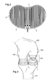
- the measuring device is intended to be arranged under a tensor 100 which spreads the tibia 101 of the femur 102.
- a tensor 100 which spreads the tibia 101 of the femur 102.
- Such tensors are well known, the tensor 100 will not be described in more detail here.
- the illustrated tensor here makes it possible to separate or bring together each condyl of the femur 102 of the tibia 101 independently.
- This tensor example is of course not limiting and the measuring device can be placed in service under any type of tensor. .
- the tibia 101 was cut and the femoral condyles 102 partially cut for joint prosthesis placement. Then, a surgeon introduced the tensor 100 to the knee joint and the measuring device of the invention.
- the measuring device 1 comprises a substrate 2 having a first face placed in service on the cut portion of the tibia 101 to cover said portion.
- the measuring device also comprises an input network 3, a first output network 4 and a second output network 5 electrically conductive, each network 3, 4, 5 having parallel branches which are interconnected in the manner of a comb.
- the networks 3, 4, 5 extend on a second face of the substrate 2 opposite to the first face so that a first part of the branches of the input network 3 extend parallel and alternately with the branches of the first network. 4 to extend in service under a first condyle 103 of the femur 102.
- a second part of the branches of the input network 3 extend parallel and alternately with the branches of the second output network 5 so as to extend in use under a second condyle 104 of the femur 102.
- the substrate 2 is a circuit board type card, the networks being made by conventional techniques of photo-printing and etching. Other embodiments may be envisaged without departing from the scope of the invention.
- the measuring device further comprises a cushion 6 of elastically deformable and electrically conductive material which covers the second face of the substrate 2.
- the cushion 6 comprises a foam layer loaded with carbon particles which comes into direct contact with the branches of the networks 3, 4, 5.
- the device is thus shaped so as to completely cover the cut portion of the tibia 101.
- the substrate 2, the input network 3, the two output networks 4, 5 and the cushion 6 covering the second face of the substrate 2 form a unitary assembly 1 encapsulated here in a deformable silicone envelope leaving only three wires leaving each network connecting to a data processing member (not shown here).
- the surgeon shifts the femur 102 relative to the tibia 101.
- the cushion 6 is then crushed locally according to the force exerted by the condyles of the femur 102 on the tibia 101.
- the processor measures a voltage between the input network 3 and the first output network 4 and between the input network 3 and the second output network 5 to characterize the force exerted by each of the condyles 103, 104 on the tibia 101. Thanks to the advantageous arrangement of the branches of the networks 3, 4, 5, three son are sufficient for the device to perform this comparison.
- the surgeon can then, from the measurements obtained for different knee flexion angle, precisely determine the dimensions of the prosthesis adapted to the patient and refine the cut of the femur 102 so as to balance the force exerted by each of the condyles 103, 104 on the tibia 101 and whether the knee is flexed or extended. He can also use these real-time measurements to adjust the tensor so as to balance the tensions of the ligaments linking the femur 102 to the tibia 101.
Landscapes
- Health & Medical Sciences (AREA)
- Life Sciences & Earth Sciences (AREA)
- Surgery (AREA)
- Engineering & Computer Science (AREA)
- Public Health (AREA)
- Orthopedic Medicine & Surgery (AREA)
- Veterinary Medicine (AREA)
- Transplantation (AREA)
- Nuclear Medicine, Radiotherapy & Molecular Imaging (AREA)
- Oral & Maxillofacial Surgery (AREA)
- General Health & Medical Sciences (AREA)
- Biomedical Technology (AREA)
- Heart & Thoracic Surgery (AREA)
- Animal Behavior & Ethology (AREA)
- Vascular Medicine (AREA)
- Biophysics (AREA)
- Cardiology (AREA)
- Physical Education & Sports Medicine (AREA)
- Pathology (AREA)
- Medical Informatics (AREA)
- Molecular Biology (AREA)
- Prostheses (AREA)
Applications Claiming Priority (1)
| Application Number | Priority Date | Filing Date | Title |
|---|---|---|---|
| FR1056225A FR2963228B1 (fr) | 2010-07-28 | 2010-07-28 | Dispositif de mesure d'un effort exerce par un femur sur un tibia en vue d'une pose de prothese articulaire |
Publications (1)
| Publication Number | Publication Date |
|---|---|
| EP2412331A1 true EP2412331A1 (de) | 2012-02-01 |
Family
ID=43640647
Family Applications (1)
| Application Number | Title | Priority Date | Filing Date |
|---|---|---|---|
| EP11174357A Withdrawn EP2412331A1 (de) | 2010-07-28 | 2011-07-18 | Vorrichtung zum Messen einer von einem Femur auf eine Tibia ausgeführten Anstrengung im Hinblick auf die Implantation einer Gelenkprothese |
Country Status (2)
| Country | Link |
|---|---|
| EP (1) | EP2412331A1 (de) |
| FR (1) | FR2963228B1 (de) |
Cited By (1)
| Publication number | Priority date | Publication date | Assignee | Title |
|---|---|---|---|---|
| CN109223256A (zh) * | 2018-11-02 | 2019-01-18 | 南阳市中心医院 | 膝关节单髁置换手术用衬垫试模及配套的使用方法 |
Citations (7)
| Publication number | Priority date | Publication date | Assignee | Title |
|---|---|---|---|---|
| GB2222258A (en) * | 1988-07-29 | 1990-02-28 | David Coates | Tactile pressure sensor |
| WO1992017113A1 (en) | 1991-04-05 | 1992-10-15 | N.K. Biotechnical Engineering Company | Knee joint load measuring instrument |
| US5510812A (en) | 1994-04-22 | 1996-04-23 | Hasbro, Inc. | Piezoresistive input device |
| US5656785A (en) * | 1995-08-07 | 1997-08-12 | The Charles Stark Draper Laboratory, Inc. | Micromechanical contact load force sensor for sensing magnitude and distribution of loads and tool employing micromechanical contact load force sensor |
| US20060007172A1 (en) * | 2004-06-23 | 2006-01-12 | Interlink Electronics, Inc. | Force sensing resistor with calibration element and method of manufacturing same |
| US20060184067A1 (en) * | 2005-02-15 | 2006-08-17 | Clemson University | Contact sensors and methods for making same |
| US20070219561A1 (en) | 2006-03-20 | 2007-09-20 | Perception Raisonnement Action En Medecine | Distractor system |
-
2010
- 2010-07-28 FR FR1056225A patent/FR2963228B1/fr active Active
-
2011
- 2011-07-18 EP EP11174357A patent/EP2412331A1/de not_active Withdrawn
Patent Citations (7)
| Publication number | Priority date | Publication date | Assignee | Title |
|---|---|---|---|---|
| GB2222258A (en) * | 1988-07-29 | 1990-02-28 | David Coates | Tactile pressure sensor |
| WO1992017113A1 (en) | 1991-04-05 | 1992-10-15 | N.K. Biotechnical Engineering Company | Knee joint load measuring instrument |
| US5510812A (en) | 1994-04-22 | 1996-04-23 | Hasbro, Inc. | Piezoresistive input device |
| US5656785A (en) * | 1995-08-07 | 1997-08-12 | The Charles Stark Draper Laboratory, Inc. | Micromechanical contact load force sensor for sensing magnitude and distribution of loads and tool employing micromechanical contact load force sensor |
| US20060007172A1 (en) * | 2004-06-23 | 2006-01-12 | Interlink Electronics, Inc. | Force sensing resistor with calibration element and method of manufacturing same |
| US20060184067A1 (en) * | 2005-02-15 | 2006-08-17 | Clemson University | Contact sensors and methods for making same |
| US20070219561A1 (en) | 2006-03-20 | 2007-09-20 | Perception Raisonnement Action En Medecine | Distractor system |
Non-Patent Citations (1)
| Title |
|---|
| MAALEJ N ET AL: "A conductive polymer pressure sensor", 19881104; 19881104 - 19881107, 4 November 1988 (1988-11-04), pages 770 - 771, XP010074750 * |
Cited By (2)
| Publication number | Priority date | Publication date | Assignee | Title |
|---|---|---|---|---|
| CN109223256A (zh) * | 2018-11-02 | 2019-01-18 | 南阳市中心医院 | 膝关节单髁置换手术用衬垫试模及配套的使用方法 |
| CN109223256B (zh) * | 2018-11-02 | 2024-02-02 | 南阳市中心医院 | 膝关节单髁置换手术用衬垫试模及配套的使用方法 |
Also Published As
| Publication number | Publication date |
|---|---|
| FR2963228B1 (fr) | 2012-08-03 |
| FR2963228A1 (fr) | 2012-02-03 |
Similar Documents
| Publication | Publication Date | Title |
|---|---|---|
| EP1599140B1 (de) | Kniegelenkdistraktor | |
| FR2539613A1 (fr) | Appareil de controle du metabolisme | |
| CA2281301C (en) | Monolithic silicon intra-ocular pressure sensor and method therefor | |
| CN106659369B (zh) | 光学连接器和医疗设备 | |
| CN105555181B (zh) | 识别受试者的耳朵中的对象的方法 | |
| EP3589227B1 (de) | Vorrichtung zur mandibulären befestigung eines ortsmarkers | |
| EP2499958A1 (de) | Optischer bispektraler Kopf zum einmaligen Gebrauch für ein Videoendoskop, und entsprechendes Videoendoskop | |
| EP2643671B1 (de) | Miniaturisierter drucksensor | |
| US20200100664A1 (en) | Endoscopic device | |
| US20210290441A1 (en) | Electronic capsular tension ring | |
| FR2787015A1 (fr) | Prothese de disque intervertebral a corps compressible | |
| EP0766542B1 (de) | Struktur zum halten des sprunggelenkes | |
| WO2023089063A1 (en) | Architecture of a photonic integrated circuit (pic) and method for operating the same as well as an optical coupler | |
| EP2412331A1 (de) | Vorrichtung zum Messen einer von einem Femur auf eine Tibia ausgeführten Anstrengung im Hinblick auf die Implantation einer Gelenkprothese | |
| DE69508085D1 (de) | Elektrische verbindungen | |
| EP1130905A3 (de) | Bildaufnahmevorrichtung | |
| CN106104791B (zh) | 安装构造体的制造方法、安装用夹具、安装构造体的制造装置、摄像装置以及内窥镜装置 | |
| EP3275024B1 (de) | Ein piezoelektrischer sensor und ein instrument mit einem solchen sensor | |
| FR2831053A1 (fr) | Ancillaire pour la preparation de la mise en place d'une prothese | |
| EP1553881A1 (de) | Scherkraftmikrosensor und endstück einer chirurgischen vorrichtung | |
| Arechvo et al. | New total ossicular replacement prostheses with a resilient joint: experimental data from human temporal bones | |
| FR2902345A1 (fr) | Prothese cardiaque monobloc implantable en position anatomique | |
| WO2008000931A1 (fr) | Carte electronique pourvue d'un connecteur en deux parties et procede de fabrication d'une telle carte | |
| FR2774477A1 (fr) | Module a fibres optiques | |
| FR3122080A1 (fr) | Dispositif médical de mesure |
Legal Events
| Date | Code | Title | Description |
|---|---|---|---|
| AK | Designated contracting states |
Kind code of ref document: A1 Designated state(s): AL AT BE BG CH CY CZ DE DK EE ES FI FR GB GR HR HU IE IS IT LI LT LU LV MC MK MT NL NO PL PT RO RS SE SI SK SM TR |
|
| AX | Request for extension of the european patent |
Extension state: BA ME |
|
| PUAI | Public reference made under article 153(3) epc to a published international application that has entered the european phase |
Free format text: ORIGINAL CODE: 0009012 |
|
| 17P | Request for examination filed |
Effective date: 20120724 |
|
| 17Q | First examination report despatched |
Effective date: 20130308 |
|
| GRAP | Despatch of communication of intention to grant a patent |
Free format text: ORIGINAL CODE: EPIDOSNIGR1 |
|
| RAP1 | Party data changed (applicant data changed or rights of an application transferred) |
Owner name: AMPLITUDE |
|
| RIC1 | Information provided on ipc code assigned before grant |
Ipc: A61F 2/30 20060101ALI20170327BHEP Ipc: A61B 90/00 20160101AFI20170327BHEP |
|
| INTG | Intention to grant announced |
Effective date: 20170410 |
|
| STAA | Information on the status of an ep patent application or granted ep patent |
Free format text: STATUS: THE APPLICATION IS DEEMED TO BE WITHDRAWN |
|
| 18D | Application deemed to be withdrawn |
Effective date: 20170822 |
|
| RIC1 | Information provided on ipc code assigned before grant |
Ipc: A61F 2/30 20060101ALI20170327BHEP Ipc: A61B 90/00 20160101AFI20170327BHEP |
|
| RIC1 | Information provided on ipc code assigned before grant |
Ipc: A61F 2/30 20060101ALI20170327BHEP Ipc: A61B 90/00 20160101AFI20170327BHEP |