EP2412448A2 - Capsule et piston - Google Patents
Capsule et piston Download PDFInfo
- Publication number
- EP2412448A2 EP2412448A2 EP11174826A EP11174826A EP2412448A2 EP 2412448 A2 EP2412448 A2 EP 2412448A2 EP 11174826 A EP11174826 A EP 11174826A EP 11174826 A EP11174826 A EP 11174826A EP 2412448 A2 EP2412448 A2 EP 2412448A2
- Authority
- EP
- European Patent Office
- Prior art keywords
- capsule
- piston
- section
- angle
- transition
- Prior art date
- Legal status (The legal status is an assumption and is not a legal conclusion. Google has not performed a legal analysis and makes no representation as to the accuracy of the status listed.)
- Granted
Links
Images


Classifications
-
- B—PERFORMING OPERATIONS; TRANSPORTING
- B05—SPRAYING OR ATOMISING IN GENERAL; APPLYING FLUENT MATERIALS TO SURFACES, IN GENERAL
- B05C—APPARATUS FOR APPLYING FLUENT MATERIALS TO SURFACES, IN GENERAL
- B05C17/00—Hand tools or apparatus using hand held tools, for applying liquids or other fluent materials to, for spreading applied liquids or other fluent materials on, or for partially removing applied liquids or other fluent materials from, surfaces
- B05C17/005—Hand tools or apparatus using hand held tools, for applying liquids or other fluent materials to, for spreading applied liquids or other fluent materials on, or for partially removing applied liquids or other fluent materials from, surfaces for discharging material from a reservoir or container located in or on the hand tool through an outlet orifice by pressure without using surface contacting members like pads or brushes
- B05C17/00503—Details of the outlet element
-
- A—HUMAN NECESSITIES
- A61—MEDICAL OR VETERINARY SCIENCE; HYGIENE
- A61C—DENTISTRY; APPARATUS OR METHODS FOR ORAL OR DENTAL HYGIENE
- A61C5/00—Filling or capping teeth
- A61C5/60—Devices specially adapted for pressing or mixing capping or filling materials, e.g. amalgam presses
- A61C5/62—Applicators, e.g. syringes or guns
-
- A—HUMAN NECESSITIES
- A61—MEDICAL OR VETERINARY SCIENCE; HYGIENE
- A61C—DENTISTRY; APPARATUS OR METHODS FOR ORAL OR DENTAL HYGIENE
- A61C5/00—Filling or capping teeth
- A61C5/60—Devices specially adapted for pressing or mixing capping or filling materials, e.g. amalgam presses
- A61C5/66—Capsules for filling material
-
- B—PERFORMING OPERATIONS; TRANSPORTING
- B05—SPRAYING OR ATOMISING IN GENERAL; APPLYING FLUENT MATERIALS TO SURFACES, IN GENERAL
- B05C—APPARATUS FOR APPLYING FLUENT MATERIALS TO SURFACES, IN GENERAL
- B05C17/00—Hand tools or apparatus using hand held tools, for applying liquids or other fluent materials to, for spreading applied liquids or other fluent materials on, or for partially removing applied liquids or other fluent materials from, surfaces
- B05C17/005—Hand tools or apparatus using hand held tools, for applying liquids or other fluent materials to, for spreading applied liquids or other fluent materials on, or for partially removing applied liquids or other fluent materials from, surfaces for discharging material from a reservoir or container located in or on the hand tool through an outlet orifice by pressure without using surface contacting members like pads or brushes
- B05C17/00503—Details of the outlet element
- B05C17/00516—Shape or geometry of the outlet orifice or the outlet element
-
- B—PERFORMING OPERATIONS; TRANSPORTING
- B05—SPRAYING OR ATOMISING IN GENERAL; APPLYING FLUENT MATERIALS TO SURFACES, IN GENERAL
- B05C—APPARATUS FOR APPLYING FLUENT MATERIALS TO SURFACES, IN GENERAL
- B05C17/00—Hand tools or apparatus using hand held tools, for applying liquids or other fluent materials to, for spreading applied liquids or other fluent materials on, or for partially removing applied liquids or other fluent materials from, surfaces
- B05C17/005—Hand tools or apparatus using hand held tools, for applying liquids or other fluent materials to, for spreading applied liquids or other fluent materials on, or for partially removing applied liquids or other fluent materials from, surfaces for discharging material from a reservoir or container located in or on the hand tool through an outlet orifice by pressure without using surface contacting members like pads or brushes
- B05C17/00576—Hand tools or apparatus using hand held tools, for applying liquids or other fluent materials to, for spreading applied liquids or other fluent materials on, or for partially removing applied liquids or other fluent materials from, surfaces for discharging material from a reservoir or container located in or on the hand tool through an outlet orifice by pressure without using surface contacting members like pads or brushes characterised by the construction of a piston as pressure exerting means, or of the co-operating container
- B05C17/00579—Hand tools or apparatus using hand held tools, for applying liquids or other fluent materials to, for spreading applied liquids or other fluent materials on, or for partially removing applied liquids or other fluent materials from, surfaces for discharging material from a reservoir or container located in or on the hand tool through an outlet orifice by pressure without using surface contacting members like pads or brushes characterised by the construction of a piston as pressure exerting means, or of the co-operating container comprising means for allowing entrapped air to escape to the atmosphere
-
- A—HUMAN NECESSITIES
- A61—MEDICAL OR VETERINARY SCIENCE; HYGIENE
- A61M—DEVICES FOR INTRODUCING MEDIA INTO, OR ONTO, THE BODY; DEVICES FOR TRANSDUCING BODY MEDIA OR FOR TAKING MEDIA FROM THE BODY; DEVICES FOR PRODUCING OR ENDING SLEEP OR STUPOR
- A61M5/00—Devices for bringing media into the body in a subcutaneous, intra-vascular or intramuscular way; Accessories therefor, e.g. filling or cleaning devices, arm-rests
- A61M5/178—Syringes
- A61M5/31—Details
- A61M5/315—Pistons; Piston-rods; Guiding, blocking or restricting the movement of the rod or piston; Appliances on the rod for facilitating dosing ; Dosing mechanisms
- A61M5/31511—Piston or piston-rod constructions, e.g. connection of piston with piston-rod
- A61M5/31513—Piston constructions to improve sealing or sliding
-
- B—PERFORMING OPERATIONS; TRANSPORTING
- B05—SPRAYING OR ATOMISING IN GENERAL; APPLYING FLUENT MATERIALS TO SURFACES, IN GENERAL
- B05C—APPARATUS FOR APPLYING FLUENT MATERIALS TO SURFACES, IN GENERAL
- B05C17/00—Hand tools or apparatus using hand held tools, for applying liquids or other fluent materials to, for spreading applied liquids or other fluent materials on, or for partially removing applied liquids or other fluent materials from, surfaces
- B05C17/005—Hand tools or apparatus using hand held tools, for applying liquids or other fluent materials to, for spreading applied liquids or other fluent materials on, or for partially removing applied liquids or other fluent materials from, surfaces for discharging material from a reservoir or container located in or on the hand tool through an outlet orifice by pressure without using surface contacting members like pads or brushes
- B05C17/00593—Hand tools of the syringe type
-
- B—PERFORMING OPERATIONS; TRANSPORTING
- B05—SPRAYING OR ATOMISING IN GENERAL; APPLYING FLUENT MATERIALS TO SURFACES, IN GENERAL
- B05C—APPARATUS FOR APPLYING FLUENT MATERIALS TO SURFACES, IN GENERAL
- B05C17/00—Hand tools or apparatus using hand held tools, for applying liquids or other fluent materials to, for spreading applied liquids or other fluent materials on, or for partially removing applied liquids or other fluent materials from, surfaces
- B05C17/005—Hand tools or apparatus using hand held tools, for applying liquids or other fluent materials to, for spreading applied liquids or other fluent materials on, or for partially removing applied liquids or other fluent materials from, surfaces for discharging material from a reservoir or container located in or on the hand tool through an outlet orifice by pressure without using surface contacting members like pads or brushes
- B05C17/00596—The liquid or other fluent material being supplied from a rigid removable cartridge having no active dispensing means, i.e. the cartridge requiring cooperation with means of the handtool to expel the material
Definitions
- the present invention relates to a capsule for receiving and metering highly viscous materials, for example of dental materials, with a housing, wherein the housing defines an interior and has an opening for introducing a piston and a discharge opening; and wherein the housing comprises: a first housing portion defining a first cylindrical interior portion, the first housing portion having a first central longitudinal axis, a first end, and a second end; a second housing portion defining an exit nozzle, the second housing portion having a second central longitudinal axis, a first end and a second end, and the second housing portion defining an exit passage opening into the exit opening formed at the second end; and a transition portion having its first end connected to the second end of the first housing portion and the second end connected to the first end of the second housing portion; wherein the first central longitudinal axis and the second central longitudinal axis intersect at an angle ⁇ .
- the invention relates to a piston, in particular for expressing material from said capsule.
- the composites / composites have a high filler content and thus high stability and modulability.
- the materials mentioned are in units, eg. In quantities between 2 g to 5 g, bottled. Smaller quantities, such as 250 mg to 350 mg, are filled in standardized disposable plastic packaging, for example in capsules or tips.
- the application in the capsule can result in very high extrusion pressures and very large extrusion forces on the dosing tongs. While low extrusion pressures are high User safety, since the capsules can not burst, are for users such. As dentists, a long and slender dosing channel of importance to ensure a comfortable application. For precise handling, the lowest possible extrusion forces are advantageous. Between these requirements an optimized solution can be found.
- the object of the present invention is to provide a capsule and a piston for dispensing high viscosity materials, for example dental materials, wherein the dispensing is made possible with reduced extrusion pressures and low segregation of the applied material at low dead volumes.
- a capsule according to the invention for receiving and metering highly viscous materials comprises a housing, wherein the housing defines an interior and has an opening for introducing a piston and a discharge opening; and wherein the housing comprises the following sections: a first housing section defining a first, in particular cylindrical, interior portion, the first housing section having a first central longitudinal axis, a first end and a second end; a second housing portion defining an exit nozzle, the second housing portion having a second central longitudinal axis, a first end and a second end, and the second housing portion defining an exit passage opening into the exit opening formed at the second end; and a transition portion having its first end connected to the second end of the first housing portion and the second end connected to the first end of the second housing portion; wherein the first central longitudinal axis and the second central longitudinal axis at an angle ⁇ of 40 to 50 °, preferably 45 ° to cut.
- the transition section tapers between its first end and its second end, and the taper angle ⁇ is at least 50 °
- the required extrusion pressures are reduced, since the geometry of the interior favors the flow behavior.
- the flow resistance during pressing of dental materials are lowered.
- the outlet channels can be smaller in diameter. This reduces material loss in the application.
- time and effort to dispense the dental materials could be reduced by 20-30%.
- Suitable materials for the capsule are plastics such as PE, in particular PA, PBT, POM, etc., in question.
- the inner contour of the capsules has been optimized.
- the advantages are in particular due to the relatively steep taper angle ⁇ .
- the transition also reduces the tendency of the high-viscosity materials to segregate.
- highly viscous dental materials have lower flow resistance in the transition from a large inner diameter to a small inner diameter by means of a blunt cone.
- the lower limit for the taper angle is 50 °. Smaller angles significantly degrade the capsule's properties. At lower cone angles, the flow resistance increases considerably.
- a first cylinder core with a blunt cone transition (truncated cone transition) and a nozzle core with a rectangular contact surface to the truncated cone have no undercuts in the structure indicated.
- the structure can thus be produced or demolded with two cores.
- the angle ⁇ between the first central longitudinal axis and the second central longitudinal axis is preferably between 10 ° and 80 °, in particular between 30 ° and 60 °, particularly preferably between 40 ° and 45 °.
- the transition section tapers in the form of an oblique truncated cone, wherein the taper angle ⁇ corresponds to the opening angle of the cone.
- the point is located off the lot line through the center of the base circle.
- the use of an oblique or oblique truncated cone (with a large opening angle) in the transition region is necessary by the angle ⁇ between the first and the second axis.
- the oblique truncated cone can be tilted with respect to the first central longitudinal axis at an angle ( ⁇ ), wherein the angle ( ⁇ ) is in particular 10 ° to 20 °.
- ⁇ the angle
- a piston can dive deeper into the transition section, whereby the amount of Vietnameseausbringbaren material (loss material) is reduced.
- the transition section connects the first interior space section with the outlet channel, wherein the transitions between the first interior space section and the interior of the transition section or the interior of the transition section and the outlet channel can be continuous.
- the transition section connects the first interior space section with the outlet channel, wherein the transition between the transition section and the outlet channel has a wall piece which is arranged transversely to the flow direction of the filling material. In this way, a flow edge is formed.
- the wall piece may be annular and arranged perpendicular to the second central longitudinal axis.
- the diameter (d) of the interior of the transition section preferably decreases steadily and at a constant pitch from the first end to the outer boundary of the wall section.
- the second housing section can connect to the transition section via the wall piece.
- the transition between the transition section and the outlet channel may have a flow edge.
- a microscopic change of the material takes place.
- the molecular chains are partially “entschlauft” or braided and oriented in the flow direction, that is, their networking is solved.
- the viscosity changes in the boundary layer and causes a positive flow behavior in the nozzle.
- the macromolecules become entangled, entangled and / or entwined.
- a segregation of the filling material after exiting the nozzle does not take place.
- With the help of the flow edge 35 a further clearly measurable reduction and reassurance of Auspress block is achieved.
- the flow behavior is continuous and continuous without any major variations in the extrusion force.
- the diameter (d1) of the first interior space section is in particular greater than the diameter (d2) of the outlet channel.
- a flange may be formed outside in the region of the first end of the first housing portion. This is usually ring-shaped.
- the diameter (d) of the interior of the transition section decreases steadily and at a constant pitch from the first end to the second end.
- the slope can be calculated from the taper of the transition area.
- the transition section connects directly to the first housing section, and the second housing section connects directly or via the already mentioned transverse wall piece to the transition section.
- the housing wall may be reinforced in the region of the transition section.
- extrusion tools on the market. As a result, the outer contour of the collar and the bore are largely defined. As harder and harder materials are to be applied, the tools are offered with ever larger translations. As a result, the loading of the capsule increases during pressing. Typically, a conventional capsule bursts in the transition region to the nozzle. Here also the highest forces arise and the cross-section is weakened by the outlet channel. When optimizing the soil, it was calculated that a reinforcement of about 30% to 50% sufficiently increases the strength. The reinforcement is provided on the lateral surface of the transition region.
- the taper angle ⁇ is between 50 ° and 120 °, in particular between 50 ° and 70 °.
- Duller angles are less negative than more acute angles.
- the outlet channel is preferably cylindrical.
- the outlet channel may be formed as a cone, which opens at an angle of 1 ° to 3 ° to the nozzle outlet opening.
- the first diameter (d1) is in particular at least twice as large as the second diameter (d2).
- the ratio d1 / d2 may be in the range of 2.0-4.0.
- a further capsule according to the invention for receiving and metering highly viscous materials comprises a housing, wherein the housing defines an interior space and has an opening for introducing a piston and an outlet opening; and wherein the housing comprises the following sections: a first housing section defining a first, in particular cylindrical, interior portion, the first housing section having a first central longitudinal axis, a first end and a second end; a second housing portion defining an exit nozzle, the second housing portion having a second central longitudinal axis, a first end and a second end, and the second housing portion defining an exit passage opening into the exit opening formed at the second end; and a transition portion having its first end connected to the second end of the first housing portion and the second end connected to the first end of the second housing portion; wherein the first central longitudinal axis and the second central longitudinal axis intersect at an angle ⁇ of 40 to 50 °, preferably 45 °.
- the transition between the transition section and the outlet channel has a wall piece which is arranged transversely to the flow direction of
- a piston according to the invention which has an outlet channel facing end side and a wiper edge or lip, wherein a transition surface of the end face adjacent to the wiper edge, with the longitudinal axis of the piston at an angle ( ⁇ ) of 90 ° to 120 °, wherein the angle ( ⁇ ) is arranged such that in the intended direction of thrust for discharging the Filling material, the transition surface extends obliquely backwards to the outside.
- the term “outwardly” refers to a direction from the longitudinal axis of the piston to the inner walls of the capsule, the term “backwards” means a direction opposite to the intended direction of thrust of the piston relative to the capsule for dispensing the material.
- the angle ( ⁇ ) is in particular between 105 ° and 120 °.
- At least one elevation is formed on the scraping edge or lip.
- the piston can be made of a partially elastic material, which presses against the cylinder wall at high pressure. As a result of the pressure, the piston is deformed in such a way that sufficient tightness and stability between the contact surface and the cylinder inner wall is produced for the material to be dispensed.
- the contact surface of the piston may also be coated to increase lubricity.
- the piston is made of a relatively stiff and / or hard plastic to prevent jamming with the inner wall of the capsule.
- the piston may have at least one wiper lip, wherein at least one elevation is formed on the wiper lip.
- the elevation is disposed on the outer periphery of the wiper lip and provides a small clearance for venting between the inner wall of the capsule and the wiper lip.
- the piston can be symmetrical and have two sealing and wiping lips.
- the lips have three elevations on the circumference.
- the object is also achieved in particular by a combination of the capsule according to the invention and the piston according to the invention.
- a gap for example, 20 microns to 50 microns wide, be arranged. In this way, there is no bias between the edge 511a or 511b and the inner wall of the piston. In addition, air can escape through the gap (venting).
- the formation of dead corners and volumes is avoided in a combination of the inventive capsule and the piston according to the invention, since the volume of the transition region is relatively small due to the large taper angle.
- the residual amount of material in the capsule after application (which is composed of the residual material in the three areas of the capsule) is considered to be lost. Since the specialistsmanden materials can be very expensive, the lowest possible residual amount is sought.
- the piston fulfills two functions, namely a stripping of the dental material from the wall and the deepest possible immersion in the cone.
- the volume of the transition region is small because of the obtuse taper angle, the residual amount of the material remaining therein is small. The residual amount is thus determined by the residual amount in the nozzle, which is predetermined by the nozzle length and the nozzle diameter.
- the end face of the piston forms a right angle or a negative angle, for example, from -10 ° to -30 ° in the contact area to the capsule inner wall. This means that an acute angle smaller than 90 ° forms between the capsule wall and the piston.
- the edge region of the piston end wall extends, with respect to the dispensing direction, obliquely backwards. This will clean the material off the wall. Only the sliding friction between piston and cylinder has to be overcome. Adhesive effects or segregation do not occur.
- the resistance may be optimized by the use of suitable capsule and bulb materials and / or by coating the bulb, at least in the contact area. As a coating, for example Teflon dispersion or a Teflon mecanicischung in the piston material in question.
- the parts are manufactured in an injection molding process, wherein two cores are used in the capsule production, namely a first core for the cylindrical outlet nozzle and a second core for the first interior portion and the truncated cone-like transition region.
- the feasibility is ensured by the fact that there is no back-injection between the two cores.
- the cores meet each other without undercut in the right wave. Transverse forces do not occur.
- a tolerance shift is permitted by making the diameter of the conic section (second end of the transition region) greater than the diameter of the outlet nozzle by a predetermined amount (eg 0.2 mm to 0.5 mm) in the transition region.
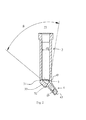
- FIG. 1 shows a capsule 1 according to the invention for receiving and for dispensing highly viscous dental materials.
- the capsule 1 is made of plastic.
- the capsule has a housing 10 which defines an interior space.
- the housing 10 has on the one hand a first opening 11 for pushing in a piston (not shown), on the other hand a second opening 12, which serves as a discharge opening for the exit of the dental material, when the piston is pressed into the interior via the first opening.
- the housing and the interior have a first section 2, a transition region 3 and a second section 4 (outlet nozzle).
- the first section 2 has a first housing section 20, at the first end 21 of which the first opening 11 of the capsule 1 is formed. At the first end of the first housing portion 20, an outwardly extending flange 22 is also formed, which in particular runs in a circle around the edge of the opening 11.
- the interior of the first housing portion 20 is substantially cylindrical with a circular cross-section, constant diameter d1, and a first central longitudinal axis 23. At the second end 24 of the first housing portion 20 immediately follows a first end 31 of the transition region 3.
- the second end 32 of the transition region opens into the second section 4, which is designed as a cylindrical outlet nozzle with a second central longitudinal axis 43.
- the inner diameter d2 of the second section 4 is constant and smaller than the inner diameter d1 of the first section 2. While the first end 41 of the housing 40 directly adjoins the transition region 30, the second end 42 has the outlet opening 12.
- the first central longitudinal axis 23 and the second central longitudinal axis 43 enclose an angle ⁇ of approximately 45 °.
- the interior of the transition region 3 has an inner diameter dt which continuously tapers or reduces towards its second end 32.
- the diameter dt at the first end 31 corresponds to the diameter d1 of the first housing section 20.
- the diameter dt varying along the transitional area 3 corresponds to the inner diameter d2 of the second housing section 40 at the second end 32.
- the taper is continuous and constant (within the transition area 3) Pitch. This means that the interior of the transition region 3 is limited by the lateral surface of a truncated cone.
- the cone corresponding to the truncated cone is an oblique (slate) cone with an opening angle ⁇ , which corresponds to the taper angle.
- the opening angle ⁇ is about 55 ° in the present embodiment.
- the taper is relatively steep, which surprisingly leads to lower extrusion forces in the interior at constant application times and less segregation of the dental material.
- a material thickening 33 in the region of the housing wall, which intersects the first longitudinal axis 23, provides the necessary stability to accommodate the high loads during the discharge of the material.
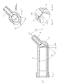
- FIG. 3 is another sectional view.
- the section extends through the outlet nozzle 2 and the transition region 3.
- the interior of the transition region 3 (delimited by the wall 30) opens at a taper angle ⁇ in the outlet channel bounded by the wall 40.
- the flow behavior can be improved while at the same time reducing the tendency for segregation.
- the metering forces can be significantly reduced compared with conventionally used nozzles, ie. H. in the application of lower forces are required, whereby the force during dosing can be reduced.
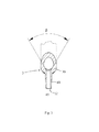
- FIG. 4 shows an embodiment of a plunger / piston 5 according to the invention for dispensing dental material, for example, from a capsule 1 as described above.
- the plunger 5 is inserted through the first opening 11 and pressed in the direction of the outlet nozzle 4 down. Due to the reduction in volume, the residual air initially escapes to the rear, after which the material flows out of the outlet opening 12.
- the plunger 5 is usually made of plastic. It has a base body 50 with an end face 51, which is first inserted into the interior of the capsule.
- the end face 51 forms with the inner wall of the capsule a right angle or the end wall closes with the capsule wall an acute angle of less than 90 °, d. H. There is a negative angle of -10 ° to -30 °. This will clean the material off the wall. Essentially, only the sliding friction between the piston 5 and the inner wall of the cylinder has to be overcome. Adhesive effects or segregation are avoided.
- the resistance can be optimized by coating the piston, in particular in the area of the contact surface / edge 52. Overall, the resistance between the piston and cylinder inner wall is reduced.
- the piston 5 is symmetrical has two outwardly projecting sealing and wiping edges or lips 52, which exert low friction on the walls of the capsule.
- the piston 5 has two sealing and wiping lips.
- FIG. 5 is a plan view of the end face 51 of a piston 5 according to the invention, the piston of the FIG. 4 like.
- the piston 5 in this embodiment (at both sealing lips respectively) three elevations 55, which increase the frictional resistance to the capsule walls by about 3% to 5%. This force is not noticeable in the application, but ensures that the piston is held securely in the capsule and (especially during packaging) is not lost.
- the space between the capsule wall and the sealing edge created by the elevations is so small that although venting is possible, ie, air can enter between the sealing lips, but the dental material can not pass through the gap.
- the capsule is basically like the one in the FIGS. 1 to 3 illustrated and described capsule constructed. Corresponding components are therefore identified by the same reference numerals as in the previous embodiment.
- the angle ⁇ between the first central longitudinal axis 23 and the second central longitudinal axis 43 is approximately 45 °.
- the transition region 3 corresponds to a truncated cone.
- the wall piece 35 is an approximately annular wall portion, preferably with a width of 0.1 mm to 0.25 mm.
- the wall piece 35 is perpendicular to the flow direction or to the longitudinal axis 43 of the second section 4 (outlet nozzle) and acts as a kind of aperture.
- the annular wall section adjoins, on the one hand, the conical region of the transitional region 3 and, on the other hand, the first end 41 of the housing 40 of the second section 4.
- the annular wall portion forming part 44 of the housing 40 forms a kind of projection for the filling material flowing into the outlet nozzle 4.
- the transition edge or flow edge 36 between the annular wall section 35 and the second section 4 is sharp-edged.
- the tapered section of the transitional region 3 has been tilted relative to the first section 2.
- the cone is tilted in the direction of the second longitudinal axis 43.
- the angle ⁇ of the tilt is here 10 °.
- the flow is not affected by the tilt.
- residual material remains in the capsule. In the present embodiment, this residual material can be reduced, since the tilting of the piston can dip deeper into the conical transition region 3. The loss of material in a dispensing operation can thus be reduced by about 30%, wherein the loss of material in the nozzle remains unchanged from the first embodiment.
- FIG. 9 a third embodiment of a piston 5 according to the invention is shown. Unless otherwise described, the piston 5 corresponds to the previously described embodiments. Corresponding components are therefore identified by the same reference numerals as in the previous embodiments.
- the piston 5 has a main body 50 with a front end face 51a and a rear end face 51b.
- the piston 5 is symmetrical with respect to the front and rear portions.
- the end faces 51a and 51b each have a concave projection 510a and 510b, respectively.
- the piston 5 is preferably made of a relatively hard plastic.
- the end faces 51a and 51b are respectively bounded by a circular wiper edge 511a or 511b, which has a radius such that between the inner wall of the capsule and the wiper edge 511a or 511b (at least when the piston is unloaded) a gap, for example from 20 microns to 50 microns wide, is present.
- a gap for example from 20 microns to 50 microns wide.
- the conditions are (as in the boundary layer) so that Auspress practitioner reduced and jamming can be prevented.
- air can escape through the gap (venting).
- the filling material is scraped by the piston 5 from the inner wall of the capsule.
- a transition surface 512a or 512b is arranged between the projection 510a or 510b and the respective edge 511a or 511b.
- This is substantially annular, but runs with a negative slope to the edge 511a and 511b out.
- the surface 512a or 512b in the case of a plan view of the respective end face 51a or 51b, falls toward the edge 511a or 511b, towards the outside. This shows especially clearly the FIG. 10 in which the negative slope of the surface 512a is drawn.
- the angle d is a measure of the slope of the surface 512a toward the outside.
- the angle ⁇ is preferably about 105 ° to 120 °.
- the injection process can be designed so that the cylinder radius decreases in the direction of the longitudinal axis L to the center controlled about 0.2 mm. Ie. the piston has a longitudinally concave cylinder surface. This avoids unwanted jamming of the piston 5 in the capsule.
- FIGS. 11 and 12 show another feature of the third embodiment of the piston 5. This feature may, but need not be, part of the third embodiment.
- projections or ribs 55 are formed at the periphery of the outer jacket wall of the piston 5. These have an overlap with the capsule of about 0.1 mm to 0.2 mm.
- the piston is thus, when it is inserted into the capsule, held in this and can not fall out or be pulled out. Tolerances are reliably compensated by the projections and the piston 5 is held in the capsule with reproducible forces.
- the piston is clamped over the projections 55 with the capsule.
- the forces exerted by it only about 3% to 5% of the extrusion forces, this additional force is not noticeable when deploying for the user.
- the pistons can not be lost because they are held securely in the capsules.
- Three (3) to six (6) ribs can be attached, depending on the capsule and piston material and the behavior of the polymers (filler).
- capsules and pistons act together in different combinations as described above. The result is improved spreading of the filler with lower extrusion forces, higher reliability, and lower requirements for the design of the capsule extrusion dies.
Landscapes
- Health & Medical Sciences (AREA)
- Mechanical Engineering (AREA)
- Engineering & Computer Science (AREA)
- Animal Behavior & Ethology (AREA)
- Oral & Maxillofacial Surgery (AREA)
- Dentistry (AREA)
- Epidemiology (AREA)
- Life Sciences & Earth Sciences (AREA)
- General Health & Medical Sciences (AREA)
- Public Health (AREA)
- Veterinary Medicine (AREA)
- Geometry (AREA)
- Physics & Mathematics (AREA)
- Dental Tools And Instruments Or Auxiliary Dental Instruments (AREA)
- Coating Apparatus (AREA)
Applications Claiming Priority (1)
| Application Number | Priority Date | Filing Date | Title |
|---|---|---|---|
| DE102010036782A DE102010036782A1 (de) | 2010-07-30 | 2010-07-30 | Kapsel und Kolben |
Publications (3)
| Publication Number | Publication Date |
|---|---|
| EP2412448A2 true EP2412448A2 (fr) | 2012-02-01 |
| EP2412448A3 EP2412448A3 (fr) | 2016-03-16 |
| EP2412448B1 EP2412448B1 (fr) | 2017-09-06 |
Family
ID=44653983
Family Applications (1)
| Application Number | Title | Priority Date | Filing Date |
|---|---|---|---|
| EP11174826.5A Active EP2412448B1 (fr) | 2010-07-30 | 2011-07-21 | Capsule et piston |
Country Status (4)
| Country | Link |
|---|---|
| US (1) | US8684731B2 (fr) |
| EP (1) | EP2412448B1 (fr) |
| JP (1) | JP2012071110A (fr) |
| DE (2) | DE202010015594U1 (fr) |
Cited By (3)
| Publication number | Priority date | Publication date | Assignee | Title |
|---|---|---|---|---|
| WO2020025485A1 (fr) | 2018-07-31 | 2020-02-06 | Voco Gmbh | Dispositif de réception et d'application de matériau dentaire et procédé |
| DE102018126140A1 (de) | 2018-10-22 | 2020-04-23 | Voco Gmbh | Vorrichtung mit einem thermochromen Temperaturindikator zur Aufnahme, Erwärmung und Applikation von Dentalmaterialien |
| DE102021103980A1 (de) | 2021-02-19 | 2022-08-25 | Universität Rostock, Körperschaft des öffentlichen Rechts | Anordnung zur Aufnahme und/oder Applikation eines Dentalkomposits |
Families Citing this family (5)
| Publication number | Priority date | Publication date | Assignee | Title |
|---|---|---|---|---|
| DE102009017980B4 (de) * | 2009-04-21 | 2012-12-06 | Heraeus Kulzer Gmbh | Kunststoffkapsel zum Lagern und Ausbringen von fließfähigen Dentalwerkstoffen sowie deren Verwendung |
| DE102010060308B4 (de) * | 2010-11-02 | 2025-03-27 | Dentsply International Inc. | Vorrichtung und Verfahren zur Mehrfachabfüllung hochviskoser Materialien |
| JP6274804B2 (ja) * | 2013-09-30 | 2018-02-07 | 株式会社松風 | 屈曲部が拡張する粘性材料収容容器 |
| JP6253938B2 (ja) * | 2013-09-30 | 2017-12-27 | 株式会社松風 | 環状接触するピストンを有する粘性材料収容容器 |
| JP6635698B2 (ja) * | 2015-07-14 | 2020-01-29 | ぺんてる株式会社 | 抵抗構造によりプランジャの可動範囲を制限したアプリケータ |
Family Cites Families (15)
| Publication number | Priority date | Publication date | Assignee | Title |
|---|---|---|---|---|
| US2381785A (en) * | 1941-12-15 | 1945-08-07 | Morris J Thompson | Dental hydrocolloid syringe |
| DE3148490C2 (de) * | 1981-12-08 | 1986-02-13 | Alfred Fischbach Kg Kunststoff-Spritzgusswerk, 5250 Engelskirchen | Bodenverschluß für einen hohlzylindrischen Strangpreßbehälter |
| US5083921A (en) * | 1989-02-06 | 1992-01-28 | Dragan William B | Dental syringe tip |
| US4963093A (en) * | 1989-02-06 | 1990-10-16 | Dragan William B | Dental syringe tip and syringe holder therefor |
| US5122057A (en) * | 1991-01-07 | 1992-06-16 | Centrix, Inc. | Dosing dental cartridge |
| US5172807A (en) * | 1991-09-30 | 1992-12-22 | Centrix, Inc. | Cement mixing capsule |
| US5322440A (en) * | 1992-10-20 | 1994-06-21 | Kerr Manufacturing Company | Dental syringe tip |
| US5460523A (en) * | 1994-07-14 | 1995-10-24 | Jeneric/Pentron | Dental composite cartridge |
| DE19651981C1 (de) * | 1996-12-13 | 1998-07-23 | Ivoclar Ag | Spritze für viskose Massen und Verfahren zur Herstellung einer Spritze für viskose Massen |
| DE19700480A1 (de) * | 1997-01-09 | 1998-07-16 | Saremco Ag | Dentalpatrone |
| US6503084B2 (en) * | 2000-02-24 | 2003-01-07 | Dentsply Detrey G.M.B.H. | Method for dispensing dental materials |
| US6379152B1 (en) * | 2000-04-19 | 2002-04-30 | Centrix, Inc. | Dental capsule for placement of ultra-high viscosity dental composite material |
| AU2003200509A1 (en) * | 2002-02-27 | 2003-09-11 | Centrix, Inc | Dental capsule for placement of high viscosity dental composite material with reduced extrusion force |
| US20030196914A1 (en) * | 2002-04-18 | 2003-10-23 | 3M Innovative Properties Company | Containers for photocurable materials |
| DE10218859B4 (de) | 2002-04-26 | 2006-05-24 | Heraeus Kulzer Gmbh | Kapsel aus Kunststoff zur Aufbewahrung und Abgabe von Dentalmaterial |
-
2010
- 2010-07-30 DE DE202010015594U patent/DE202010015594U1/de not_active Expired - Lifetime
- 2010-07-30 DE DE102010036782A patent/DE102010036782A1/de not_active Withdrawn
-
2011
- 2011-07-21 EP EP11174826.5A patent/EP2412448B1/fr active Active
- 2011-07-28 JP JP2011165440A patent/JP2012071110A/ja active Pending
- 2011-08-01 US US13/195,339 patent/US8684731B2/en active Active
Non-Patent Citations (1)
| Title |
|---|
| None |
Cited By (6)
| Publication number | Priority date | Publication date | Assignee | Title |
|---|---|---|---|---|
| WO2020025485A1 (fr) | 2018-07-31 | 2020-02-06 | Voco Gmbh | Dispositif de réception et d'application de matériau dentaire et procédé |
| US11730566B2 (en) | 2018-07-31 | 2023-08-22 | Voco Gmbh | Device for storage and application and method |
| DE102018126140A1 (de) | 2018-10-22 | 2020-04-23 | Voco Gmbh | Vorrichtung mit einem thermochromen Temperaturindikator zur Aufnahme, Erwärmung und Applikation von Dentalmaterialien |
| EP3643270A1 (fr) | 2018-10-22 | 2020-04-29 | VOCO GmbH | Dispositif doté d'un indicateur de température thermochromique permettant de recevoir, chauffer et appliquer des matières dentaires |
| DE102018126140B4 (de) | 2018-10-22 | 2023-12-07 | Voco Gmbh | Vorrichtung mit einem thermochromen Temperaturindikator zur Aufnahme, Erwärmung und Applikation von Dentalmaterialien |
| DE102021103980A1 (de) | 2021-02-19 | 2022-08-25 | Universität Rostock, Körperschaft des öffentlichen Rechts | Anordnung zur Aufnahme und/oder Applikation eines Dentalkomposits |
Also Published As
| Publication number | Publication date |
|---|---|
| US20120028217A1 (en) | 2012-02-02 |
| EP2412448B1 (fr) | 2017-09-06 |
| DE202010015594U1 (de) | 2011-05-05 |
| JP2012071110A (ja) | 2012-04-12 |
| DE102010036782A1 (de) | 2012-02-02 |
| EP2412448A3 (fr) | 2016-03-16 |
| US8684731B2 (en) | 2014-04-01 |
Similar Documents
| Publication | Publication Date | Title |
|---|---|---|
| EP2412448B1 (fr) | Capsule et piston | |
| EP0645122B1 (fr) | Seringue de dosage de substances visqueuses, en particulier de substances dentaires | |
| EP2444336B1 (fr) | Dispositif de distribution double | |
| DE7518809U (de) | Pipettenspitze | |
| DE202005001203U1 (de) | Mehrkomponentenfolienbehälter | |
| DE102006047289A1 (de) | Kartuschenkolben | |
| DE29502783U1 (de) | Behälter zum Lagern und Ausbringen einer Dentalmasse | |
| EP2885087B1 (fr) | Dispositif de sortie | |
| EP0094033B1 (fr) | Récipient pour masses plastiques | |
| EP3127601A1 (fr) | Dispositif de melange, en particulier pour ciment osseux | |
| DE3005855A1 (de) | Bodenverschluss fuer einen hohlzylindrischen strangpressbehaelter | |
| EP0641228A1 (fr) | Dispositif d'injection a usage unique. | |
| DE10060614A1 (de) | Spitze zum dosierten Abgeben von dentalen Werkstoffen | |
| DE102016122041A1 (de) | Mehrkomponentenbehältnis | |
| DE10194907B4 (de) | Gewindekonstruktion | |
| WO2011073251A1 (fr) | Cartouche avec bouchon de fermeture | |
| DE19750090B4 (de) | Kanüle für einen Luer- oder Luerlockanschluß | |
| EP1836100B1 (fr) | Piston tubulaire pour une cartouche destinée à exprimer des substances pâteuses | |
| DE19945706C2 (de) | Kartusche und Dentalapplikator | |
| EP0103746A2 (fr) | Dispositif dispensateur en forme de bâton | |
| EP2210823B1 (fr) | Dispositif de distribution | |
| WO2018083221A1 (fr) | Piston fabriqué dans un procédé de moulage par injection de matière synthétique pour une seringue médicale et seringue médicale | |
| DE3719252A1 (de) | Spender zur ausgabe pastoeser massen | |
| EP2975487B1 (fr) | Dispositif destiné à doser et mélanger deux composants pouvant s'écouler | |
| DE202006015313U1 (de) | Kartuschenkolben |
Legal Events
| Date | Code | Title | Description |
|---|---|---|---|
| AK | Designated contracting states |
Kind code of ref document: A2 Designated state(s): AL AT BE BG CH CY CZ DE DK EE ES FI FR GB GR HR HU IE IS IT LI LT LU LV MC MK MT NL NO PL PT RO RS SE SI SK SM TR |
|
| AX | Request for extension of the european patent |
Extension state: BA ME |
|
| PUAI | Public reference made under article 153(3) epc to a published international application that has entered the european phase |
Free format text: ORIGINAL CODE: 0009012 |
|
| PUAL | Search report despatched |
Free format text: ORIGINAL CODE: 0009013 |
|
| AK | Designated contracting states |
Kind code of ref document: A3 Designated state(s): AL AT BE BG CH CY CZ DE DK EE ES FI FR GB GR HR HU IE IS IT LI LT LU LV MC MK MT NL NO PL PT RO RS SE SI SK SM TR |
|
| AX | Request for extension of the european patent |
Extension state: BA ME |
|
| RIC1 | Information provided on ipc code assigned before grant |
Ipc: B05C 17/005 20060101AFI20160209BHEP |
|
| 17P | Request for examination filed |
Effective date: 20160912 |
|
| RBV | Designated contracting states (corrected) |
Designated state(s): AL AT BE BG CH CY CZ DE DK EE ES FI FR GB GR HR HU IE IS IT LI LT LU LV MC MK MT NL NO PL PT RO RS SE SI SK SM TR |
|
| RIC1 | Information provided on ipc code assigned before grant |
Ipc: A61M 5/315 20060101ALN20170329BHEP Ipc: B05C 17/005 20060101AFI20170329BHEP Ipc: A61C 5/62 20170101ALI20170329BHEP |
|
| GRAP | Despatch of communication of intention to grant a patent |
Free format text: ORIGINAL CODE: EPIDOSNIGR1 |
|
| STAA | Information on the status of an ep patent application or granted ep patent |
Free format text: STATUS: GRANT OF PATENT IS INTENDED |
|
| INTG | Intention to grant announced |
Effective date: 20170526 |
|
| GRAS | Grant fee paid |
Free format text: ORIGINAL CODE: EPIDOSNIGR3 |
|
| GRAA | (expected) grant |
Free format text: ORIGINAL CODE: 0009210 |
|
| STAA | Information on the status of an ep patent application or granted ep patent |
Free format text: STATUS: THE PATENT HAS BEEN GRANTED |
|
| AK | Designated contracting states |
Kind code of ref document: B1 Designated state(s): AL AT BE BG CH CY CZ DE DK EE ES FI FR GB GR HR HU IE IS IT LI LT LU LV MC MK MT NL NO PL PT RO RS SE SI SK SM TR |
|
| REG | Reference to a national code |
Ref country code: GB Ref legal event code: FG4D Free format text: NOT ENGLISH |
|
| REG | Reference to a national code |
Ref country code: CH Ref legal event code: EP Ref country code: AT Ref legal event code: REF Ref document number: 925294 Country of ref document: AT Kind code of ref document: T Effective date: 20170915 |
|
| REG | Reference to a national code |
Ref country code: IE Ref legal event code: FG4D Free format text: LANGUAGE OF EP DOCUMENT: GERMAN |
|
| REG | Reference to a national code |
Ref country code: DE Ref legal event code: R096 Ref document number: 502011012942 Country of ref document: DE |
|
| REG | Reference to a national code |
Ref country code: NL Ref legal event code: MP Effective date: 20170906 |
|
| REG | Reference to a national code |
Ref country code: LT Ref legal event code: MG4D |
|
| PG25 | Lapsed in a contracting state [announced via postgrant information from national office to epo] |
Ref country code: NO Free format text: LAPSE BECAUSE OF FAILURE TO SUBMIT A TRANSLATION OF THE DESCRIPTION OR TO PAY THE FEE WITHIN THE PRESCRIBED TIME-LIMIT Effective date: 20171206 Ref country code: FI Free format text: LAPSE BECAUSE OF FAILURE TO SUBMIT A TRANSLATION OF THE DESCRIPTION OR TO PAY THE FEE WITHIN THE PRESCRIBED TIME-LIMIT Effective date: 20170906 Ref country code: LT Free format text: LAPSE BECAUSE OF FAILURE TO SUBMIT A TRANSLATION OF THE DESCRIPTION OR TO PAY THE FEE WITHIN THE PRESCRIBED TIME-LIMIT Effective date: 20170906 Ref country code: SE Free format text: LAPSE BECAUSE OF FAILURE TO SUBMIT A TRANSLATION OF THE DESCRIPTION OR TO PAY THE FEE WITHIN THE PRESCRIBED TIME-LIMIT Effective date: 20170906 Ref country code: HR Free format text: LAPSE BECAUSE OF FAILURE TO SUBMIT A TRANSLATION OF THE DESCRIPTION OR TO PAY THE FEE WITHIN THE PRESCRIBED TIME-LIMIT Effective date: 20170906 |
|
| REG | Reference to a national code |
Ref country code: CH Ref legal event code: NV Representative=s name: DR. GRAF AND PARTNER AG INTELLECTUAL PROPERTY, CH |
|
| PG25 | Lapsed in a contracting state [announced via postgrant information from national office to epo] |
Ref country code: ES Free format text: LAPSE BECAUSE OF FAILURE TO SUBMIT A TRANSLATION OF THE DESCRIPTION OR TO PAY THE FEE WITHIN THE PRESCRIBED TIME-LIMIT Effective date: 20170906 Ref country code: GR Free format text: LAPSE BECAUSE OF FAILURE TO SUBMIT A TRANSLATION OF THE DESCRIPTION OR TO PAY THE FEE WITHIN THE PRESCRIBED TIME-LIMIT Effective date: 20171207 Ref country code: RS Free format text: LAPSE BECAUSE OF FAILURE TO SUBMIT A TRANSLATION OF THE DESCRIPTION OR TO PAY THE FEE WITHIN THE PRESCRIBED TIME-LIMIT Effective date: 20170906 Ref country code: BG Free format text: LAPSE BECAUSE OF FAILURE TO SUBMIT A TRANSLATION OF THE DESCRIPTION OR TO PAY THE FEE WITHIN THE PRESCRIBED TIME-LIMIT Effective date: 20171206 Ref country code: LV Free format text: LAPSE BECAUSE OF FAILURE TO SUBMIT A TRANSLATION OF THE DESCRIPTION OR TO PAY THE FEE WITHIN THE PRESCRIBED TIME-LIMIT Effective date: 20170906 |
|
| PG25 | Lapsed in a contracting state [announced via postgrant information from national office to epo] |
Ref country code: NL Free format text: LAPSE BECAUSE OF FAILURE TO SUBMIT A TRANSLATION OF THE DESCRIPTION OR TO PAY THE FEE WITHIN THE PRESCRIBED TIME-LIMIT Effective date: 20170906 |
|
| PG25 | Lapsed in a contracting state [announced via postgrant information from national office to epo] |
Ref country code: CZ Free format text: LAPSE BECAUSE OF FAILURE TO SUBMIT A TRANSLATION OF THE DESCRIPTION OR TO PAY THE FEE WITHIN THE PRESCRIBED TIME-LIMIT Effective date: 20170906 Ref country code: PL Free format text: LAPSE BECAUSE OF FAILURE TO SUBMIT A TRANSLATION OF THE DESCRIPTION OR TO PAY THE FEE WITHIN THE PRESCRIBED TIME-LIMIT Effective date: 20170906 Ref country code: RO Free format text: LAPSE BECAUSE OF FAILURE TO SUBMIT A TRANSLATION OF THE DESCRIPTION OR TO PAY THE FEE WITHIN THE PRESCRIBED TIME-LIMIT Effective date: 20170906 |
|
| PG25 | Lapsed in a contracting state [announced via postgrant information from national office to epo] |
Ref country code: EE Free format text: LAPSE BECAUSE OF FAILURE TO SUBMIT A TRANSLATION OF THE DESCRIPTION OR TO PAY THE FEE WITHIN THE PRESCRIBED TIME-LIMIT Effective date: 20170906 Ref country code: SM Free format text: LAPSE BECAUSE OF FAILURE TO SUBMIT A TRANSLATION OF THE DESCRIPTION OR TO PAY THE FEE WITHIN THE PRESCRIBED TIME-LIMIT Effective date: 20170906 Ref country code: IT Free format text: LAPSE BECAUSE OF FAILURE TO SUBMIT A TRANSLATION OF THE DESCRIPTION OR TO PAY THE FEE WITHIN THE PRESCRIBED TIME-LIMIT Effective date: 20170906 Ref country code: SK Free format text: LAPSE BECAUSE OF FAILURE TO SUBMIT A TRANSLATION OF THE DESCRIPTION OR TO PAY THE FEE WITHIN THE PRESCRIBED TIME-LIMIT Effective date: 20170906 Ref country code: IS Free format text: LAPSE BECAUSE OF FAILURE TO SUBMIT A TRANSLATION OF THE DESCRIPTION OR TO PAY THE FEE WITHIN THE PRESCRIBED TIME-LIMIT Effective date: 20180106 |
|
| REG | Reference to a national code |
Ref country code: DE Ref legal event code: R097 Ref document number: 502011012942 Country of ref document: DE |
|
| PLBE | No opposition filed within time limit |
Free format text: ORIGINAL CODE: 0009261 |
|
| STAA | Information on the status of an ep patent application or granted ep patent |
Free format text: STATUS: NO OPPOSITION FILED WITHIN TIME LIMIT |
|
| REG | Reference to a national code |
Ref country code: FR Ref legal event code: PLFP Year of fee payment: 8 |
|
| PG25 | Lapsed in a contracting state [announced via postgrant information from national office to epo] |
Ref country code: DK Free format text: LAPSE BECAUSE OF FAILURE TO SUBMIT A TRANSLATION OF THE DESCRIPTION OR TO PAY THE FEE WITHIN THE PRESCRIBED TIME-LIMIT Effective date: 20170906 |
|
| 26N | No opposition filed |
Effective date: 20180607 |
|
| PG25 | Lapsed in a contracting state [announced via postgrant information from national office to epo] |
Ref country code: SI Free format text: LAPSE BECAUSE OF FAILURE TO SUBMIT A TRANSLATION OF THE DESCRIPTION OR TO PAY THE FEE WITHIN THE PRESCRIBED TIME-LIMIT Effective date: 20170906 |
|
| PG25 | Lapsed in a contracting state [announced via postgrant information from national office to epo] |
Ref country code: MT Free format text: LAPSE BECAUSE OF FAILURE TO SUBMIT A TRANSLATION OF THE DESCRIPTION OR TO PAY THE FEE WITHIN THE PRESCRIBED TIME-LIMIT Effective date: 20170906 |
|
| PGFP | Annual fee paid to national office [announced via postgrant information from national office to epo] |
Ref country code: AT Payment date: 20180719 Year of fee payment: 8 |
|
| PG25 | Lapsed in a contracting state [announced via postgrant information from national office to epo] |
Ref country code: LU Free format text: LAPSE BECAUSE OF NON-PAYMENT OF DUE FEES Effective date: 20180721 Ref country code: MC Free format text: LAPSE BECAUSE OF FAILURE TO SUBMIT A TRANSLATION OF THE DESCRIPTION OR TO PAY THE FEE WITHIN THE PRESCRIBED TIME-LIMIT Effective date: 20170906 |
|
| REG | Reference to a national code |
Ref country code: BE Ref legal event code: MM Effective date: 20180731 |
|
| REG | Reference to a national code |
Ref country code: IE Ref legal event code: MM4A |
|
| PG25 | Lapsed in a contracting state [announced via postgrant information from national office to epo] |
Ref country code: IE Free format text: LAPSE BECAUSE OF NON-PAYMENT OF DUE FEES Effective date: 20180721 |
|
| PG25 | Lapsed in a contracting state [announced via postgrant information from national office to epo] |
Ref country code: BE Free format text: LAPSE BECAUSE OF NON-PAYMENT OF DUE FEES Effective date: 20180731 |
|
| REG | Reference to a national code |
Ref country code: AT Ref legal event code: MM01 Ref document number: 925294 Country of ref document: AT Kind code of ref document: T Effective date: 20180721 |
|
| PGFP | Annual fee paid to national office [announced via postgrant information from national office to epo] |
Ref country code: FR Payment date: 20190719 Year of fee payment: 9 |
|
| PG25 | Lapsed in a contracting state [announced via postgrant information from national office to epo] |
Ref country code: AT Free format text: LAPSE BECAUSE OF NON-PAYMENT OF DUE FEES Effective date: 20180721 |
|
| PGFP | Annual fee paid to national office [announced via postgrant information from national office to epo] |
Ref country code: GB Payment date: 20190719 Year of fee payment: 9 |
|
| REG | Reference to a national code |
Ref country code: CH Ref legal event code: PL |
|
| PG25 | Lapsed in a contracting state [announced via postgrant information from national office to epo] |
Ref country code: TR Free format text: LAPSE BECAUSE OF FAILURE TO SUBMIT A TRANSLATION OF THE DESCRIPTION OR TO PAY THE FEE WITHIN THE PRESCRIBED TIME-LIMIT Effective date: 20170906 |
|
| PG25 | Lapsed in a contracting state [announced via postgrant information from national office to epo] |
Ref country code: LI Free format text: LAPSE BECAUSE OF NON-PAYMENT OF DUE FEES Effective date: 20190731 Ref country code: HU Free format text: LAPSE BECAUSE OF FAILURE TO SUBMIT A TRANSLATION OF THE DESCRIPTION OR TO PAY THE FEE WITHIN THE PRESCRIBED TIME-LIMIT; INVALID AB INITIO Effective date: 20110721 Ref country code: CH Free format text: LAPSE BECAUSE OF NON-PAYMENT OF DUE FEES Effective date: 20190731 Ref country code: PT Free format text: LAPSE BECAUSE OF FAILURE TO SUBMIT A TRANSLATION OF THE DESCRIPTION OR TO PAY THE FEE WITHIN THE PRESCRIBED TIME-LIMIT Effective date: 20170906 |
|
| PG25 | Lapsed in a contracting state [announced via postgrant information from national office to epo] |
Ref country code: CY Free format text: LAPSE BECAUSE OF FAILURE TO SUBMIT A TRANSLATION OF THE DESCRIPTION OR TO PAY THE FEE WITHIN THE PRESCRIBED TIME-LIMIT Effective date: 20170906 Ref country code: MK Free format text: LAPSE BECAUSE OF NON-PAYMENT OF DUE FEES Effective date: 20170906 |
|
| PG25 | Lapsed in a contracting state [announced via postgrant information from national office to epo] |
Ref country code: AL Free format text: LAPSE BECAUSE OF FAILURE TO SUBMIT A TRANSLATION OF THE DESCRIPTION OR TO PAY THE FEE WITHIN THE PRESCRIBED TIME-LIMIT Effective date: 20170906 |
|
| GBPC | Gb: european patent ceased through non-payment of renewal fee |
Effective date: 20200721 |
|
| PG25 | Lapsed in a contracting state [announced via postgrant information from national office to epo] |
Ref country code: GB Free format text: LAPSE BECAUSE OF NON-PAYMENT OF DUE FEES Effective date: 20200721 Ref country code: FR Free format text: LAPSE BECAUSE OF NON-PAYMENT OF DUE FEES Effective date: 20200731 |
|
| REG | Reference to a national code |
Ref country code: DE Ref legal event code: R081 Ref document number: 502011012942 Country of ref document: DE Owner name: MEDMIX SWITZERLAND AG, CH Free format text: FORMER OWNER: TRANSCODENT GMBH & CO. KG, 24149 KIEL, DE |
|
| P01 | Opt-out of the competence of the unified patent court (upc) registered |
Effective date: 20230505 |
|
| PGFP | Annual fee paid to national office [announced via postgrant information from national office to epo] |
Ref country code: DE Payment date: 20250722 Year of fee payment: 15 |