EP2412576A2 - Système d'éclairage de sortie d'urgence - Google Patents
Système d'éclairage de sortie d'urgence Download PDFInfo
- Publication number
- EP2412576A2 EP2412576A2 EP11175885A EP11175885A EP2412576A2 EP 2412576 A2 EP2412576 A2 EP 2412576A2 EP 11175885 A EP11175885 A EP 11175885A EP 11175885 A EP11175885 A EP 11175885A EP 2412576 A2 EP2412576 A2 EP 2412576A2
- Authority
- EP
- European Patent Office
- Prior art keywords
- vehicle
- egress
- indicators
- sensors
- preselected limit
- Prior art date
- Legal status (The legal status is an assumption and is not a legal conclusion. Google has not performed a legal analysis and makes no representation as to the accuracy of the status listed.)
- Withdrawn
Links
Images





Classifications
-
- G—PHYSICS
- G08—SIGNALLING
- G08B—SIGNALLING SYSTEMS, e.g. PERSONAL CALLING SYSTEMS; ORDER TELEGRAPHS; ALARM SYSTEMS
- G08B7/00—Signalling systems according to two or more of groups G08B3/00 - G08B6/00
- G08B7/06—Signalling systems according to two or more of groups G08B3/00 - G08B6/00 using electric transmission, e.g. involving audible and visible signalling through the use of sound and light sources
- G08B7/062—Signalling systems according to two or more of groups G08B3/00 - G08B6/00 using electric transmission, e.g. involving audible and visible signalling through the use of sound and light sources indicating emergency exits
-
- B—PERFORMING OPERATIONS; TRANSPORTING
- B60—VEHICLES IN GENERAL
- B60Q—ARRANGEMENT OF SIGNALLING OR LIGHTING DEVICES, THE MOUNTING OR SUPPORTING THEREOF OR CIRCUITS THEREFOR, FOR VEHICLES IN GENERAL
- B60Q3/00—Arrangement of lighting devices for vehicle interiors; Lighting devices specially adapted for vehicle interiors
- B60Q3/40—Arrangement of lighting devices for vehicle interiors; Lighting devices specially adapted for vehicle interiors specially adapted for specific vehicle types
- B60Q3/41—Arrangement of lighting devices for vehicle interiors; Lighting devices specially adapted for vehicle interiors specially adapted for specific vehicle types for mass transit vehicles, e.g. buses
- B60Q3/46—Emergency lighting, e.g. for escape routes
-
- B—PERFORMING OPERATIONS; TRANSPORTING
- B60—VEHICLES IN GENERAL
- B60Q—ARRANGEMENT OF SIGNALLING OR LIGHTING DEVICES, THE MOUNTING OR SUPPORTING THEREOF OR CIRCUITS THEREFOR, FOR VEHICLES IN GENERAL
- B60Q3/00—Arrangement of lighting devices for vehicle interiors; Lighting devices specially adapted for vehicle interiors
- B60Q3/40—Arrangement of lighting devices for vehicle interiors; Lighting devices specially adapted for vehicle interiors specially adapted for specific vehicle types
- B60Q3/41—Arrangement of lighting devices for vehicle interiors; Lighting devices specially adapted for vehicle interiors specially adapted for specific vehicle types for mass transit vehicles, e.g. buses
- B60Q3/47—Circuits; Control arrangements
Definitions
- the present invention relates to vehicle safety, more specifically to systems, devices and methods of providing cues to assist vehicle occupants in safely and quickly exiting a vehicle in the event of a catastrophic event.
- Vehicles, especially military vehicles are sometimes subject to vehicle rollover, submersion, or an explosion near the vehicle. Under these circumstances it is not unusual for the vehicle to come to rest in an orientation other than the orientation in which the vehicle normally travels. These events can be disorienting to the occupants of the vehicle and occupants may expend valuable time attempting to exit the vehicle via an exit point that is blocked by the fact that the exit point may now be in contact with the ground and therefore inoperable for egress. These events may be accompanied by smoke, fire, dust and the dislodging of the vehicle contents from normal locations. This can lead to obscuration of normal cues that the occupants of the vehicle use to identify exit points as well as obscuration of operating controls for doors and hatches.
- night vision goggles While night vision goggles assist in low light situations some are designed to automatically deactivate in the presence of white light. Night vision goggles also alter color sensitivity and color perception.
- Vehicle occupants after a catastrophic event such as vehicle rollover, submersion, or an explosion near the vehicle, can benefit from additional visual aids and cues to safely egress a damaged vehicle. Due to obscuration of exit points and associated operating mechanisms (e.g. handles, latches or pull chains) by smoke, flame, dislodged objects, debris, low ambient light levels, as well as potential 'sensory disorienting' effects of the event, time can be lost by vehicle occupants attempting to locate an operable exit and egress the vehicle. The need to rapidly exit a vehicle subject to the above discussed catastrophic events is particularly relevant to situations where troops are operating a combat vehicle in battlefield conditions.
- a catastrophic event such as vehicle rollover, submersion, or an explosion near the vehicle.
- Embodiments of the present invention are directed toward an Emergency Egress Lighting System (EELS) that provides a compact, robust, and self-contained lighting system that can automatically activate illumination to aid the occupants in exiting a vehicle.
- An example embodiment of the system activates if any one or more of a variety of trigger events takes place, such as vehicle rollover, vehicle submersion, or if the vehicle absorbs a shock or pressure wave associated with an Improvised Explosive Device (IED) or other explosive detonation.
- the EELS automatically illuminates the vehicle interior space with a series of color coded LED arrays.
- the LED arrays are strategically placed to frame or highlight all egress points; as well as to mark necessary handholds, latches, or pull handles required for door or hatch activation.
- the EELS sensor module includes logic architecture that enables the system to perform 'vehicle orientation discrimination' (VOD).
- VOD identifies which egress plane (or surface of the vehicle) is positioned on the ground after a rollover event based on measured pitch angle, roll angle and gyroscopic data.
- the VOD system can include a combination of sensors that determine the final resting orientation of the vehicle and a visually designates a suggested egress route or portal based on the final orientation of the vehicle. Based on acquired data the system can activate appropriate LED lights to indicate, for example by color coding, any egress points which are potentially blocked based on the vehicles final resting orientation, while marking by different color coding or illuminating the remaining unobstructed egress points.
- a rollover condition along any vehicle axis can activate the VOD logic.
- Vehicle exits that are not blocked can be illuminated with green LEDs and exits which are potentially blocked (typically by the ground) can be illuminated with an amber colored light or another appropriate distinguishing color.
- VOD in combination with the color-coded lighting assists the vehicle operator or passengers in quickly determining the vehicle orientation and prioritizing an exit strategy.
- Alternative embodiments optionally include audible indications to vehicle occupants as to the location of potentially blocked or operable egress locations.
- the EELS system activates both visual and audible cues for the driver if the vehicle approaches its mobility limits.
- All measureable system limits and thresholds are configurable to support integration on virtually any vehicle platform.
- System limits and thresholds can include such elements as vehicle pitch or roll, and can dynamically adjust the warning limits to the operator based on the vehicle's speed, or rate of assent or descent along a trajectory.
- a battery pack can include lithium ion (LI-ion) batteries.
- LI-ion lithium ion
- the integrated battery backup capability can enable an EELS system to function, after a catastrophic event where the vehicle loses its battery system or electrical power generation capability.
- the EELS system can remain in a 'standby mode' during normal vehicle operation while simultaneously charging or recharging the battery pack from the vehicle electrical system.
- the invention marks vehicle egress points using a combination of green and/or amber wavelength light which are NVG compatible, in the event a vehicle rolls over or becomes submerged while the vehicle occupants are wearing NVG devices or if the occupants don night vision goggles as a result of a loss of normal lighting.
- the EELS system activates and marks egress points if the system senses an explosive force (acceleration) experienced by the vehicle in any of three independent axes.
- the EELS design also includes data recording/logging capability that captures all sensor data during and immediately after a catastrophic event. This enables data recovery and event reconstruction.
- This "black box' data capture approach can provide valuable measurement data that can aid vehicle engineers in designing better survivability solutions and platform upgrades. Additionally, this data can include valuable field intelligence that, once correlated with additional event data such as; vehicle damage, occupant injuries and enemy techniques, tactics and practices (TTPS) can then be used to make timely and accurate battlefield decisions and potentially save lives.
- TTPS vehicle damage, occupant injuries and enemy techniques, tactics and practices
- the data enable medical personnel to determine the level of exposure the vehicle occupants have had to extreme accelerations and pressures (e.g. head trauma) and conduct appropriate care for, for example, traumatic brain injury.
- the invention can include additional input and output (I/O) signal capability which provides integrated communication and mutual activation between the EELS system and other existing or future vehicle systems.
- I/O input and output
- the invention offers significant flexibility by supporting both current and future vehicle platform auxiliary systems, either in a stand alone or networked environment to increase occupant survivability rates.
- Fig. 1 depicts an example embodiment of an emergency egress lighting system 20 that includes three basic subsystems.
- the subsystems generally include vehicle power supply 22, sensor module 24 and LED array 26.
- Sensor module 24 includes sensors 26, I/O switches 28, hardware and processor logic 30, battery power pack 32 and power supply board 34. I/O switches 28 are positioned for operator interaction. Hardware and processor logic 30 is adapted to monitor and activate system function if a trigger event is detected. Battery power pack 32 is configured for backup energy storage in the event of a loss of vehicle power supply 22.
- LED arrays 26 subsystem includes numerous sets of lights or LEDs located or locatable adjacent to exit portals of an equipped vehicle.
- a suitable LED array 26 is LightFormTM LED strips manufactured by Grote Industries, Inc. of Madison, Indiana. LED arrays can be equipped with mounting aids such as hook-and-loop or adhesive mounting provisions.
- LED arrays 22 When in use sub parts of LED arrays 22 are located to provide emergency illumination at egress points and associated handles and latches for unlatching and opening of portals of a vehicle. LED arrays can take the form of LED strips and can also provide driver-warning indications.
- LED arrays 26 are adapted to be daylight readable and night vision goggle (NVG) compliant.
- NVG night vision goggle
- Interconnect subsystem 36 includes low profile, lightweight cable or harness that provides electrical connectivity between the Sensor Module subsystem 10 and the LED Array subsystem 22.
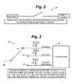
- Figs. 2 and 3 depict example I/O switches 28 that are located within a vehicle for user operation.
- Fig. 2 depicts two-position locking switch 38 that can be used to fully disengage electrical power for maintenance or based on user necessity.
- Fig. 3 depicts three-position locking toggle switch 40 that can be utilized to control a powered system.
- First position 42 enables a combat over ride mode that can be pre-configured to disable all illumination or only activate LED arrays 26 in specific scenarios.
- Second position 44 activates a system-test mode that can be used to diagnose system errors or alternatively, illuminate all LEDs continuously or in sequence to facilitate, for example, replacement of individual lighting units.
- Third default position 46 enables normal, or automatic, system operation as discussed herein.
- EELS 20 can remain in an automatic or 'standby mode' during normal vehicle operation and battery power pack 32 is under a constant electrical charge via the vehicle electrical system.
- the EELS 20 self-contained battery power pack 32 provides all electrical power required for sustained EELS 20 operation for up to 45 minutes after any potential loss of vehicle power supply 22.
- Fig. 4 depicts an example LED control scheme 48, that includes controller 50 coupled to gate driver 52 to switch individual LED array 26 units on or off at the direction of controller 50.
- Separate gate drivers 52 can be utilized for different color LED arrays 26.
- dual-output gate drivers (not shown) can be configured to operate LED arrays 26 equipped with multicolor LED arrays 26.
- LED control scheme 48 also includes other circuit components 54 as known to those of skill in the art.
- sensor module enclosure 56 includes various interfaces in one embodiment of a scalable EELS system architecture. Ports and connectors provide a variety of interfaces to enclosure 50. These ports can include USB receptacle 58, I2C port 60, power ports for vehicle power supply 22, LED output connectors 62, and various sensor 64 inputs including submersion sensor connector 66.
- the depicted enclosure 56 provides for the selection of various sensors 64, tailoring the EELS system to specific vehicle types or theatre of operations.
- Sensor 64 options include, but are not limited to pitch sensor 68, roll sensor 70, micro electrical mechanical system (MEMS) gyroscopic sensor 72, accelerometer 74, submersion sensor 76 and pressure wave (Blast) sensor 78.
- the EELS 20 is software configurable, allowing activation thresholds including, but not limited to, max pitch angle, max roll angle and acceleration rates. These rates and limits can be configured based on vehicle type (size and/or weight) and mobility specifications.
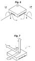
- Figs. 6 and 7 depict two sensors that can be included with EELS 20.
- Fig. 6 depicts pitch sensor 68 and roll sensor 70.
- Combination pitch sensor 68 and roll sensor 70 converts analog rotation of a vehicle along the X or Y axes into a digital signal that can be analyzed by controller 50. Rotation about the Z-axis is not depicted in this embodiment, as the changing orientation of a vehicle at normal rates during normal operation is typically not indicative of a critical event.
- Z-axis rotation of the vehicle can be collected, particularly when it occurs above a threshold rate and utilized in conjunction with the X-axis and Y-axis data.
- Fig. 7 depicts three-axis accelerometer 74.
- Three-axis accelerometer 74 alone, or in combination with other orientation sensors can be utilized to input vehicle movements to controller 50.
- controller 50 receives one or more indications from any of sensors 64 EELS 20 can identify which side of the vehicle is positioned on the ground after a rollover event based on measured pitch angle, roll angle and gyroscopic data.
- An embodiment of the system can perform real-time event data recording, allowing an operator to download all of sensor measurement data after an event for analysis, recreation, and intelligence gathering.
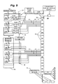
- Fig. 8 depicts an emergency egress lighting system 20 sensor module 24 with external input and output (I/O) signal capability, including integrated communication and mutual activation between the EELS system and other existing or future vehicle systems.
- I/O input and output
- both a USB port 58 and a programmable UART 80 are provided.
- Alternative wired or wireless interfaces can also optionally be included with the system.
- Fig. 9 depicts an embodiment of a sensor module 24 with multiple LED interconnections 82, as well as submersion sensor connections 66. Also depicted are two egress point LED arrays first egress point LED array 84 and second egress point LED array 86 located at first egress point 88 and second egress point 90.
- First egress point LED array 96 includes, for example five individual colored light emitting diodes 92 including two green LEDs 94 and three amber LEDS 96. In an alternate embodiment, separate green LED 94 and amber LED 96 arrays can be utilized, however, including multiple colors of LEDs 92 in a single LED array 26 can minimize the space required and installation time for the plurality LED arrays 26 that may be needed for an individual vehicle.
- Connectors 98 are disposed between sensor module 24 and first egress LED array 84 and second egress LED array 96.
- the connectors 98 provide electrical signals to the LED arrays 94, 96 and allow for individual LED arrays 26 to be replaced as needed due to failure or damage. While any of a variety of releasable or locking connectors 98 can be utilized in various embodiments of the invention, one potential supplier of military grade connectors 98 is Fischer Connections SA.
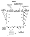
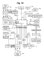
- Fig. 10 depicts an example embodiment of an EELS controller 50 interconnected with various system devices.
- Three-axis shock sensor 100 is coupled via a buffer 102 to controller 50 to provide X, Y, and Z-axes data through analog to digital converter 104 coupled to a serial peripheral interface (not shown) of controller 50.
- Associated X, Y and Z interrupt data can be indicated through at least one connection between controller 50 and an interrupt comparator 106.
- Analog tilt sensor 108 is coupled to controller 50, for example, via a sixteen-channel ADC port 110 of the controller 50 to provide X, Y, and Z-axis data.
- a depicted example analog tile sensor 108 is an ADXL325 sensor, available from Analog Devices, Inc., is a small, low power, 3-axis accelerometer with signal conditioned voltage outputs. The sensor can measure acceleration with a minimum full-scale range of ⁇ 5 g. It can measure the static acceleration of gravity in tilt-sensing applications, as well as dynamic acceleration, resulting from motion, shock, or vibration.
- any number individual submersion sensors 76 can be located on various portions of a vehicle to detect partial submersion of one section or side of the vehicle. In the depicted embodiment three submersion sensors 76 are buffered into 16-channel ADC port 110 of controller 50.
- One exemplary shock sensor 100 is the ADXL001 accelerometer, available from Analog Devices, Inc., that can provide g-force data along the axis of the sensors orientation. Three depicted shock sensors 100 can be oriented such that each sensor detects acceleration in one of the three separate X, Y, and Z-axes. Shock sensor 100 can be coupled to controller 50 via a buffer that provides analog data from each axis of movement as well as an interrupt comparator that can provide a signal to the controller 100 indicating that sensor data is available.
- An example first gyroscope 114 is a STMicroelectronics LPR510AL dual-axis gyro, which can measure the angular rates of rotation about the pitch (X) and roll (Y) axes. Two separate analog voltage outputs for each axis can provide angular velocity ranges to controller 50. Vehicle yaw, or orientation, can be measured with example second gyroscope 116, which can include the LY510ALH single axis gyroscope, also available from STMicroelectronics. Both first gyroscope 114 and second gyroscope 116 can be coupled to a sixteen-channel ADC port 110 of controller 50.
- digital tilt sensor 118 can also be coupled to controller 50 via a 12C bus 120.
- digital tilt sensor is an ADXL345 sensor which includes a small, thin, low power, 3-axis accelerometer with high-resolution (13-bit) measurement at ⁇ 16 g.
- a plurality of LED arrays 26 include multiple LEDs of various colors and be coupled to controller 50 via a system of MOSFETs 122, gate drivers 124 and digital isolators 126. As understood by those skilled in the art, other lighting configurations can alternatively be utilized.
- controller 50 Additional connections to controller 50 include: a backup battery management system 128 coupled to battery power pack 32 and electrically erasable programmable read only memory 130 (EEPROM) coupled to controller 50 via 12C bus 132, a USB receptacle 134, system switches 136 and system status indicators 138 such as fuel status, system mode, and fault indicators.
- EEPROM electrically erasable programmable read only memory
- An embodiment of an emergency egress lighting system 20 can be provided as a kit (not shown) in a small, robust and self-contained package including sensor module 24, battery power pack 32, interconnect subsystem 36, and set of LED arrays 26 that can be removably mounted to an existing vehicle interior.
- the assembled kit (not shown) can automatically activate color coded LED arrays, providing visual cues to occupants, aiding in their egress of the vehicle.
- Moisture sensors 140 can also be located external to the vehicle to provide sensing of the presence of water such as when the vehicle becomes submerged or partially submerged. Controller 50 is operably coupled to moisture sensors 140 and is programmed to determine which of first egress point 88 and second egress point are not submerged and to illuminate first egress LED array 84 or second egress LED array 86 to indicate a preferable exit.
- EELS 20 can automatically activate when any one of the following configurable trigger events takes place:
- EELS 20 In the presence of any one of these measured 'trigger' events, EELS 20 automatically illuminates the vehicle interior space with a series of LED arrays 26. Trigger points are software configurable and can be adjusted to coincide with particular vehicle platform specifications. In one embodiment the system can illuminate nine independent egress points 88, 98.
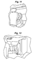
- Fig. 11 depicts an example vehicle driver's side door illumination in green light from right rear-passenger perspective.
- Fig. 12 depicts an example vehicle driver's side door illumination in green light and in comparison the commander's (passenger) side door is not illuminated. This lighting scenario can indicate to the vehicle occupants that egress is likely available through the driver's side of the vehicle.
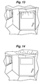
- Fig. 13 depicts a crew exit door illuminated in green, indicating that the exit is likely operable.
- Fig. 14 depicts a crew exit door illuminated in amber and roof hatches illuminated in green. This scenario indicates that the vehicle has exceeded its climb angle, or that the vehicle has come to rest on its backside, preventing or hindering the use of the rear hatch exit.
- An alternative escape route is indicated at the roof hatches that are illuminated in green.
- Fig. 15 depicts various LED arrays marking exit hatch handles for a M1114 vehicle.
- Fig. 16 depicts LED arrays making left edge of rear access and Driver's door handle and locking pin. These LED arrays can help to highlight and indicate the location of various handles and mechanisms in a vehicle after a catastrophic event. By providing visual indications of the locations of the exit points, and their respective operating mechanisms, the time required for occupants of a vehicle to egress the vehicle can be reduced.
- the LED arrays generate illumination in a green color indicating that the depicted exits should be usable.
Landscapes
- Engineering & Computer Science (AREA)
- Mechanical Engineering (AREA)
- Business, Economics & Management (AREA)
- Emergency Management (AREA)
- Physics & Mathematics (AREA)
- General Physics & Mathematics (AREA)
- Lighting Device Outwards From Vehicle And Optical Signal (AREA)
- Arrangements Of Lighting Devices For Vehicle Interiors, Mounting And Supporting Thereof, Circuits Therefore (AREA)
- Non-Portable Lighting Devices Or Systems Thereof (AREA)
Applications Claiming Priority (2)
| Application Number | Priority Date | Filing Date | Title |
|---|---|---|---|
| US36940010P | 2010-07-30 | 2010-07-30 | |
| US13/188,776 US20120029765A1 (en) | 2010-07-30 | 2011-07-22 | Emergency egress lighting system |
Publications (2)
| Publication Number | Publication Date |
|---|---|
| EP2412576A2 true EP2412576A2 (fr) | 2012-02-01 |
| EP2412576A3 EP2412576A3 (fr) | 2013-06-19 |
Family
ID=45315430
Family Applications (1)
| Application Number | Title | Priority Date | Filing Date |
|---|---|---|---|
| EP11175885.0A Withdrawn EP2412576A3 (fr) | 2010-07-30 | 2011-07-28 | Système d'éclairage de sortie d'urgence |
Country Status (2)
| Country | Link |
|---|---|
| US (1) | US20120029765A1 (fr) |
| EP (1) | EP2412576A3 (fr) |
Cited By (2)
| Publication number | Priority date | Publication date | Assignee | Title |
|---|---|---|---|---|
| CN107933421A (zh) * | 2016-10-13 | 2018-04-20 | 矢崎总业株式会社 | 车载呈现照明系统 |
| WO2023129034A1 (fr) * | 2021-12-28 | 2023-07-06 | Fnss Savunma Si̇stemleri̇ A.Ş. | Système d'éclairage de secours |
Families Citing this family (3)
| Publication number | Priority date | Publication date | Assignee | Title |
|---|---|---|---|---|
| CN105637372B (zh) * | 2013-09-09 | 2019-06-14 | 罗伯特·博世有限公司 | 振动传感器 |
| WO2015071383A1 (fr) * | 2013-11-13 | 2015-05-21 | Seb Ip Holdings Limited | Support d'œuvre d'art |
| CA3170057A1 (fr) | 2020-02-06 | 2021-09-10 | Austin Star Detonator Company | Capteurs integres pour detonateur |
Family Cites Families (18)
| Publication number | Priority date | Publication date | Assignee | Title |
|---|---|---|---|---|
| US4347499A (en) * | 1981-01-02 | 1982-08-31 | Thomas F. Burkman, Sr. | Emergency guidance system |
| US4365232A (en) * | 1981-03-23 | 1982-12-21 | The United States Of America As Represented By The Secretary Of The Navy | Emergency lighting unit |
| US4794373A (en) * | 1986-08-27 | 1988-12-27 | Collins & Aikman Corporation | Lighting strip apparatus for visually guiding the occupants of a structure |
| GB2214681A (en) * | 1988-01-22 | 1989-09-06 | Neville Hamilton Birch | Emergency evacuation and guidance means |
| NO934463L (no) * | 1993-12-08 | 1995-06-09 | Jan Erik Vadseth | Lysanordning med styrbare lyskilder samt lyslist med sådanne lyskilder |
| GB9508065D0 (en) * | 1995-04-20 | 1995-06-07 | Saf T Glo Ltd | Emergency lighting |
| US5797673A (en) * | 1995-11-22 | 1998-08-25 | Nsi Enterprises, Inc. | Emergency lighting unit/exit sign combination |
| GB2365113B (en) * | 2000-07-25 | 2004-11-10 | Stg Aerospace Ltd | Improvements in or relating to emergency lighting |
| GB0027863D0 (en) * | 2000-11-15 | 2000-12-27 | Bligh Maurice | Emergency floor lighting system |
| US7259656B1 (en) * | 2001-11-13 | 2007-08-21 | Ch2M Hill Industrial Design & Construction, Inc. | System and method for displaying safe exit routes during an emergency condition |
| FR2838402B1 (fr) * | 2002-04-15 | 2004-12-24 | Airbus | Dispositif d'aide a l'evacuation d'urgence d'un aeronef |
| WO2006077475A1 (fr) * | 2005-01-18 | 2006-07-27 | Richard Kennedy | Systeme de guidage d'evacuation incendie assiste par laser |
| US8475024B2 (en) * | 2007-04-14 | 2013-07-02 | Saf-T-Glo Limited | Emergency lighting |
| US20090066522A1 (en) * | 2007-09-11 | 2009-03-12 | Il- Won Tech Co., Ltd | Emergency guidance lamp system for guiding to nearest exit in the event of fire |
| US8120376B2 (en) * | 2007-12-12 | 2012-02-21 | Novellus Systems, Inc. | Fault detection apparatuses and methods for fault detection of semiconductor processing tools |
| US7579945B1 (en) * | 2008-06-20 | 2009-08-25 | International Business Machines Corporation | System and method for dynamically and efficently directing evacuation of a building during an emergency condition |
| US8083367B2 (en) * | 2008-12-12 | 2011-12-27 | Anderson Jerry T | Emergency exit route illumination system and methods |
| GB2472090B (en) * | 2009-07-24 | 2011-06-08 | Aeroglow Ltd | A lighting system |
-
2011
- 2011-07-22 US US13/188,776 patent/US20120029765A1/en not_active Abandoned
- 2011-07-28 EP EP11175885.0A patent/EP2412576A3/fr not_active Withdrawn
Non-Patent Citations (1)
| Title |
|---|
| None |
Cited By (2)
| Publication number | Priority date | Publication date | Assignee | Title |
|---|---|---|---|---|
| CN107933421A (zh) * | 2016-10-13 | 2018-04-20 | 矢崎总业株式会社 | 车载呈现照明系统 |
| WO2023129034A1 (fr) * | 2021-12-28 | 2023-07-06 | Fnss Savunma Si̇stemleri̇ A.Ş. | Système d'éclairage de secours |
Also Published As
| Publication number | Publication date |
|---|---|
| US20120029765A1 (en) | 2012-02-02 |
| EP2412576A3 (fr) | 2013-06-19 |
Similar Documents
| Publication | Publication Date | Title |
|---|---|---|
| EP2412576A2 (fr) | Système d'éclairage de sortie d'urgence | |
| ES1241974U (es) | Sistemas y metodos de estabilidad de carga suspendida | |
| JP6985312B2 (ja) | バッテリー及びバッテリー付き無人機 | |
| CN107352022B (zh) | 一种耐碰撞四旋翼球形无人机系统 | |
| US10689102B2 (en) | Vertical take-off and landing aircraft | |
| US8497465B2 (en) | Orientation sensing switch system for a head-mounted electronic device | |
| ES2231386T3 (es) | Cardan comun estabilizado. | |
| ES2792068T3 (es) | Unidad de luz de emergencia autónoma para una aeronave y sistema de iluminación de emergencia que comprende tal unidad de luz | |
| CN106444800A (zh) | 多旋翼无人机飞行用外置式安全控制装置、方法及系统 | |
| CN205899386U (zh) | 多旋翼无人机飞行用外置式安全控制装置及系统 | |
| CN108820198B (zh) | 基于八旋翼飞行器的多功能救援机器人 | |
| WO2020116826A1 (fr) | Dispositif de prévention de chute pour drone | |
| US20090109064A1 (en) | Simplified self-powered attitude survival indicator | |
| WO2013180450A1 (fr) | Système de détection de débarquement sécurisé de passagers par utilisation d'une caméra et son procédé | |
| CA2747518A1 (fr) | Systeme d'eclairage d'evacuation d'urgence | |
| JPH06255594A (ja) | 機体状態を表示する無人航空機 | |
| US8253337B2 (en) | Lighting system | |
| GB2404154A (en) | Combined electrical and gas connection for a respiratory device | |
| EP3902980B1 (fr) | Appareil d'éclairage et procédé d'utilisation associé | |
| KR100980489B1 (ko) | 자동차 운행형태 및 속도에 대응하는 졸음운전 경고방법 및장치 | |
| KR102174439B1 (ko) | 비상 탈출 유도 및 환경 조명을 위한 지능형 객실 조명 시스템 및 그 방법 | |
| WO2015130038A1 (fr) | Tripode de signalisation de trafic | |
| US9845163B2 (en) | Display assembly, use of a display assembly, and aircraft assembly having such a display assembly | |
| KR102603567B1 (ko) | 구명조끼 부착용 지능형 조난 알림모듈 및 이를 이용한 해상조난 관리시스템 | |
| EP4706781A1 (fr) | Appareil de surveillance de la pression partielle d'oxygène et d'alerte d'un utilisateur d'un risque imminent d'hypoxie |
Legal Events
| Date | Code | Title | Description |
|---|---|---|---|
| AK | Designated contracting states |
Kind code of ref document: A2 Designated state(s): AL AT BE BG CH CY CZ DE DK EE ES FI FR GB GR HR HU IE IS IT LI LT LU LV MC MK MT NL NO PL PT RO RS SE SI SK SM TR |
|
| AX | Request for extension of the european patent |
Extension state: BA ME |
|
| PUAI | Public reference made under article 153(3) epc to a published international application that has entered the european phase |
Free format text: ORIGINAL CODE: 0009012 |
|
| PUAL | Search report despatched |
Free format text: ORIGINAL CODE: 0009013 |
|
| AK | Designated contracting states |
Kind code of ref document: A3 Designated state(s): AL AT BE BG CH CY CZ DE DK EE ES FI FR GB GR HR HU IE IS IT LI LT LU LV MC MK MT NL NO PL PT RO RS SE SI SK SM TR |
|
| AX | Request for extension of the european patent |
Extension state: BA ME |
|
| RIC1 | Information provided on ipc code assigned before grant |
Ipc: B60Q 3/02 20060101AFI20130515BHEP |
|
| STAA | Information on the status of an ep patent application or granted ep patent |
Free format text: STATUS: THE APPLICATION IS DEEMED TO BE WITHDRAWN |
|
| 18D | Application deemed to be withdrawn |
Effective date: 20131220 |