EP2412593A1 - Mit einem hydraulischen Verstärker belüftete Eingansschubstange mit Kolben - Google Patents
Mit einem hydraulischen Verstärker belüftete Eingansschubstange mit Kolben Download PDFInfo
- Publication number
- EP2412593A1 EP2412593A1 EP11175522A EP11175522A EP2412593A1 EP 2412593 A1 EP2412593 A1 EP 2412593A1 EP 11175522 A EP11175522 A EP 11175522A EP 11175522 A EP11175522 A EP 11175522A EP 2412593 A1 EP2412593 A1 EP 2412593A1
- Authority
- EP
- European Patent Office
- Prior art keywords
- booster
- poppet
- chamber
- input rod
- vent path
- Prior art date
- Legal status (The legal status is an assumption and is not a legal conclusion. Google has not performed a legal analysis and makes no representation as to the accuracy of the status listed.)
- Granted
Links
- 239000012530 fluid Substances 0.000 claims abstract description 53
- 238000004891 communication Methods 0.000 claims abstract description 13
- 230000001105 regulatory effect Effects 0.000 description 8
- 230000007423 decrease Effects 0.000 description 2
- 230000003247 decreasing effect Effects 0.000 description 2
- 238000012986 modification Methods 0.000 description 2
- 230000004048 modification Effects 0.000 description 2
- 238000013022 venting Methods 0.000 description 2
- 230000004075 alteration Effects 0.000 description 1
- 230000000295 complement effect Effects 0.000 description 1
- 230000001276 controlling effect Effects 0.000 description 1
- 230000008878 coupling Effects 0.000 description 1
- 238000010168 coupling process Methods 0.000 description 1
- 238000005859 coupling reaction Methods 0.000 description 1
- 230000000994 depressogenic effect Effects 0.000 description 1
- 238000003825 pressing Methods 0.000 description 1
- 230000001737 promoting effect Effects 0.000 description 1
- 238000010926 purge Methods 0.000 description 1
- 238000007789 sealing Methods 0.000 description 1
Images




Classifications
-
- B—PERFORMING OPERATIONS; TRANSPORTING
- B60—VEHICLES IN GENERAL
- B60T—VEHICLE BRAKE CONTROL SYSTEMS OR PARTS THEREOF; BRAKE CONTROL SYSTEMS OR PARTS THEREOF, IN GENERAL; ARRANGEMENT OF BRAKING ELEMENTS ON VEHICLES IN GENERAL; PORTABLE DEVICES FOR PREVENTING UNWANTED MOVEMENT OF VEHICLES; VEHICLE MODIFICATIONS TO FACILITATE COOLING OF BRAKES
- B60T13/00—Transmitting braking action from initiating means to ultimate brake actuator with power assistance or drive; Brake systems incorporating such transmitting means, e.g. air-pressure brake systems
- B60T13/10—Transmitting braking action from initiating means to ultimate brake actuator with power assistance or drive; Brake systems incorporating such transmitting means, e.g. air-pressure brake systems with fluid assistance, drive, or release
- B60T13/12—Transmitting braking action from initiating means to ultimate brake actuator with power assistance or drive; Brake systems incorporating such transmitting means, e.g. air-pressure brake systems with fluid assistance, drive, or release the fluid being liquid
- B60T13/14—Transmitting braking action from initiating means to ultimate brake actuator with power assistance or drive; Brake systems incorporating such transmitting means, e.g. air-pressure brake systems with fluid assistance, drive, or release the fluid being liquid using accumulators or reservoirs fed by pumps
- B60T13/142—Systems with master cylinder
- B60T13/145—Master cylinder integrated or hydraulically coupled with booster
-
- B—PERFORMING OPERATIONS; TRANSPORTING
- B60—VEHICLES IN GENERAL
- B60T—VEHICLE BRAKE CONTROL SYSTEMS OR PARTS THEREOF; BRAKE CONTROL SYSTEMS OR PARTS THEREOF, IN GENERAL; ARRANGEMENT OF BRAKING ELEMENTS ON VEHICLES IN GENERAL; PORTABLE DEVICES FOR PREVENTING UNWANTED MOVEMENT OF VEHICLES; VEHICLE MODIFICATIONS TO FACILITATE COOLING OF BRAKES
- B60T13/00—Transmitting braking action from initiating means to ultimate brake actuator with power assistance or drive; Brake systems incorporating such transmitting means, e.g. air-pressure brake systems
- B60T13/10—Transmitting braking action from initiating means to ultimate brake actuator with power assistance or drive; Brake systems incorporating such transmitting means, e.g. air-pressure brake systems with fluid assistance, drive, or release
- B60T13/12—Transmitting braking action from initiating means to ultimate brake actuator with power assistance or drive; Brake systems incorporating such transmitting means, e.g. air-pressure brake systems with fluid assistance, drive, or release the fluid being liquid
- B60T13/16—Transmitting braking action from initiating means to ultimate brake actuator with power assistance or drive; Brake systems incorporating such transmitting means, e.g. air-pressure brake systems with fluid assistance, drive, or release the fluid being liquid using pumps directly, i.e. without interposition of accumulators or reservoirs
- B60T13/161—Systems with master cylinder
- B60T13/165—Master cylinder integrated or hydraulically coupled with booster
Definitions
- the invention relates to a booster in a braking application, and in particular to a hydraulic booster assembly.
- a booster assembly provides braking assistance to an operator of a vehicle during a braking operation.
- the booster assembly is mechanically energized by the engine or by an electrically driven pump.
- a vacuum booster assembly has historically been used to provide the booster functionality. Hydraulic boosters are also used. In either case (vacuum or hydraulic), the booster assembly provides a force to a primary piston of a master cylinder that is proportional to the amount of the brake pedal force that is applied by the operator.
- the master cylinder functionality may be provided by a separate master cylinder assembly, or the functionality may be integrated within the booster assembly.
- fluid pressure from a high pressure source is regulated by a booster valve in response to the brake pedal force.
- Fluid within a booster chamber which is at the regulated pressure, is applied to the primary piston of the master cylinder portion of the combination in order to move the primary piston from a rest position (i.e., an unapplied position) to an applied position.
- the master cylinder and the primary piston define a primary chamber which is in fluid communication with a braking circuit. Moving the primary piston pressurizes fluid in the primary chamber, thereby pressurizing fluid in the braking circuit.
- the booster fluid that is within the booster chamber must be vented to reduce or eliminate the pressure applied to the primary piston by the fluid in the booster chamber. Without proper venting of the fluid in the booster chamber, the trapped fluid impedes or prevents the desired return of the primary piston to the unapplied position.
- a hydraulic brake booster system includes a primary piston axially moveable within a bore of a cylinder, a booster chamber located rearwardly of the primary piston within the bore, an input rod extending within the booster chamber, a booster vent path in selective fluid communication with the booster chamber, and a seal member located between the forward face and the primary piston, the seal member in a fixed relationship with the input rod and configured to (i) seal the booster vent path from the booster chamber when the input rod is in a first position, and (ii) not seal the booster vent path from the booster chamber when the input rod is moved rearwardly within the booster chamber to a second position.
- a hydraulic brake booster system includes a cylinder bore, a primary piston axially moveable within the cylinder bore, a booster chamber defined between the primary piston and a sleeve bearing, an input rod extending forwardly through the sleeve bearing toward the primary piston, a booster vent path extending rearwardly from a forward face of the input rod, and an annular seal member fixedly associated with the input rod and movable therewith, the seal member positioned between the forward face of the input rod and the primary piston and configured to form a seal with the primary piston isolating the booster vent path from the booster chamber.
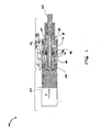
- FIG. 1 depicts a fragmentary cross sectional view of an integrated hydraulic booster-master cylinder assembly (brake system), depicted in a first position;
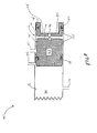
- FIG. 2 depicts a cross sectional view of the master cylinder portion of the brake system depicted in FIG. 1 ;
- FIG. 3 depicts an exploded cross sectional view of a poppet assembly and an input rod of a brake booster assembly, depicted in FIG. 1 ;
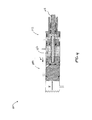
- FIG. 4 depicts a fragmentary cross sectional view of the brake system of FIG. 1 depicted in a second position
- FIG. 5 depicts a fragmentary cross sectional view of the brake system of FIG. 1 depicted in a third position
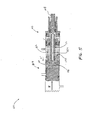
- FIG. 6 depicts a fragmentary cross sectional view of the brake system of FIG. 1 depicted in a fourth position
- FIG. 7 depicts a fragmentary cross sectional view of the brake system of FIG. 1 with an alternative vent path through the primary piston
- FIG. 8 depicts a cross sectional view of a master cylinder portion of the brake system depicted in FIG. 7 .
- the braking system 100 includes an integrated hydraulic booster-master cylinder assembly that contains a boost chamber portion 102.
- the boost chamber portion 102 depicted in FIG. 1 is sealingly coupled with a master cylinder portion 104 by a seal 106.
- the boost chamber portion 102 is coupled to a brake pedal (not shown) by a rod 108.
- An input rod spring (not shown) or other biasing member(s) may be coupled to the rod 108 to bias the rod 108 to an unapplied position corresponding to a released position of the braking system 100 as depicted in FIG. 1 .
- the boost chamber portion 102 may be mechanically controlled by a mechanical linkage between the brake pedal and a valve system (not shown) provided for regulating pressure within the boost chamber portion 102.
- the boost chamber portion 102 may also be electrically coupled to the brake pedal (not shown), where a sensor (not shown) coupled to the brake pedal (not shown) provides a signal to the boost chamber portion 102 to regulate pressure therein.
- the sensor (not shown) may be a brake pedal position sensor or a brake pedal force sensor.
- the first type provides a varying electrical signal based on the position of the brake pedal (not shown).
- the second type provides a varying electrical signal based on a force applied to the brake pedal.
- a position sensor may be replaced with a force sensor for the purpose of providing an electrical signal to the valve system (not shown).
- force sensors are referenced throughout the description, it should be appreciated that a force sensor may be replaced with a position sensor for the purpose of providing an electrical signal to the valve system (not shown).
- a direct linkage between the brake pedal (not shown) and the boost chamber portion 102 may be used for the purpose of controlling the valve system (not shown) in order to control pressure within the boost chamber portion 102.
- the boost chamber portion 102 includes a poppet assembly 110, an input rod assembly 112, and a sleeve bearing assembly 114.
- the poppet assembly 110, the input rod assembly 112, and the sleeve bearing assembly 114 are disposed within a cylinder 116 having a bore 118.
- the sleeve bearing assembly 114 sealingly couples to the cylinder 116 with seals 120 and 130.
- the sleeve bearing assembly 114 sealingly couples to the input rod assembly 112 with a seal 125.
- the poppet assembly 110, the input rod assembly 112, and the sleeve bearing assembly 114 define a booster chamber 122.
- the booster chamber 122 is in fluid communication with a regulated pressure source (not shown) by a fluid inlet 124.
- the booster chamber 122 is sealed by the seals 106, 120, 125, and 154 (see FIG. 2 ).
- the sleeve bearing assembly 114 and the cylinder 116 define a low pressure chamber 126.
- the low pressure chamber 126 is in fluid communication with a reservoir (not shown) via a fluid passage 128.
- the low pressure chamber 126 is sealed from the outside of the boost chamber portion 102 by at least a seal 130 and a seal 262 (see FIG. 3 ).
- the low pressure chamber 126 includes an annular vent chamber 132, a first radial vent 134, and a second radial vent 136.
- the annular vent chamber 132 is formed by the input rod assembly 112 and a reduced diameter portion 138 of the cylinder 116.
- the first radial vent 134 extends radially inwardly from the fluid passage 128.
- the second radial vent chamber 136 extends radially inwardly from the annular vent chamber 132.
- cylinder 116 is depicted as extending uniformly between the boost chamber portion 102 and the master cylinder portion 104, the reader should appreciate that the cylinder 116 may have different dimensions about the boost chamber portion 102 as compared to the master cylinder portion 104.
- the master cylinder portion 104 includes a primary piston 150, seals 152 and 154, an inlet 156, and an outlet 158.
- the seals 152 and 154 extend annularly about the primary piston 150.
- the primary piston 150 is slidably disposed within the bore 118 of the cylinder 116.
- the primary piston 150 and the bore 118 define a primary chamber 162 for pressurizing fluid therein.
- the inlet 156 fluidly couples the primary chamber 162 with the reservoir (not shown).
- the outlet 158 fluidly couples the primary chamber 162 with a downstream braking circuit (not shown).
- the primary piston 150 includes a front portion 164 and a rear portion 166.
- the front portion 164 includes an active face 168 which provides a diameter 170.
- the front portion 164 is in contact with pressurized fluid of the primary chamber 162.
- the rear portion 166 includes an active face 172 which is in fluid communication with the booster chamber 122.
- An annular space 176 is defined between the seals 152 and 154.
- the annular space 176 is formed by a reduced area of the piston 150 between the front portion 164 and the rear portion 166 and the cylinder 116.
- the seal 152 is configured to seal the primary chamber 162 from the inlet 156 and thereby from the reservoir (not shown).
- the seal 154 is configured to seal the boost chamber 122 from the inlet 156 and thereby from the reservoir (not shown). Fluid within the annular space 176 is substantially at the pressure of the reservoir.
- the annular space 176 at certain positions of the primary piston 150 becomes in fluid communication with the inlet 156 to thereby vent fluid therein to the reservoir (not shown).
- a rearward facing cavity 182 may be formed in the rear portion 166 of the primary piston 150 to receive the poppet assembly and includes an active face 184 to interface with the poppet assembly 110 and the seal 106 (see FIG. 1 ). If the piston 150 is configured without the rearward facing cavity 182, the poppet assembly 110 may be configured to interface directly with the active face 172 of the primary piston 150.
- the poppet assembly 110 includes a forward portion 200, the seal 106, a recessed forward poppet face 202, a poppet vent path 204, and a rearward facing cavity 206.
- the recessed forward poppet face 202 is defined by an outer diameter 208 as well as an inner diameter 210.
- the diameter 210 is greater than a diameter 212 of the poppet vent path 204 and is smaller than the outer diameter 208.
- the seal 106 is positioned on the recessed forward poppet face 202. While not shown, an annular grove may be provided to receive the seal 106.
- the seal 106 may also be an over-molded member that is integrally molded with the forward portion 200.
- the poppet vent path 204 extends between an outer forward poppet face 217 and an inner portion 218 of the forward portion 200 of the poppet assembly 110.
- the seal 106 is configured to seal the poppet vent path 204 by engaging the active face 184 of the primary piston 150.
- a rear portion 214 of the poppet assembly 110 has a diameter 216.
- the input rod assembly 112 includes a forward portion 250, a forward face 252, a booster vent path 254, a rear portion 256, and a rearward cavity 258.
- the forward portion 250 interfaces with the rearward facing cavity 206 of the poppet assembly 110.
- This interface may be a press-fit, a threaded connection, or other types of interface that firmly connects the poppet assembly 110 to the input rod assembly 112.
- the booster vent path 254 is substantially aligned with the poppet vent path 204.
- the booster vent path 254 extends from the front portion 250 to the rear portion 256 terminating at the second radial vent 136.
- a seal 262 provides a sealing interface between the input rod assembly 112 and the reduced diameter portion 138 of the sleeve bearing assembly 114 (see FIG. 1 ).
- the interface between the forward face 252 and an inner portion 218 provides a limit for how far the input rod assembly 112 can be press fit into the rearward facing cavity 206 of the poppet assembly 110.
- the limit may also be provided by a frictional interface between the forward portion 200 of the poppet assembly 110 and the forward portion 250 of the input rod assembly.
- the step 264 may be configured to provide the travel limit, however, the step 264 may be preferably a square step in this configuration.
- the rearward cavity 258 receives the rod 108 (see FIG. 1 ) in an axially secure manner without restricting the angular orientation of the rod 108 relative to the input rod assembly 112.
- the braking system 100 is in the unapplied position as depicted in FIG. 1 .
- the low pressure chamber 126 which includes the first radial vent 134 and the second radial vent 136, vents to the reservoir (not shown) through the fluid passage 128.
- the booster chamber 122 is in fluid communication with the regulated pressure source (not shown) through the fluid inlet 124.
- the primary chamber 162 (see FIG. 2 ) fluidly communicates with the reservoir (not shown) through the inlet 156.
- the primary chamber 162 also fluidly communicates with the downstream braking circuit (not shown) through the outlet 158.
- the input rod spring biases the rod 108 to the right (with reference to FIG. 1 ).
- a piston spring also biases the piston 150 to the right (with reference to FIGS. 1 and 2 ).
- the piston 150 in the unapplied position the piston 150 is engaged with the poppet assembly 110.
- the pressure within the boost chamber 122 (via the fluid inlet 124) is at or near the pressure of the reservoir (not shown).
- the pressure in the low pressure chamber 126 is the same as the pressure within the reservoir (not shown).
- the rod 108 moves leftward with reference to FIG. 1 . Since the rod 108 is fixedly coupled to the input rod assembly 112, the input rod assembly 112 also moves leftward which causes the poppet assembly 110 to move leftward. The leftward movement of the poppet assembly 110 firmly seals the poppet assembly 110 against the primary piston 150 by engaging the seal 106 with the active face 184.
- the valve system coupled to the high pressure source (not shown) regulates pressure within the booster chamber 122 in response to position of the brake pedal (not shown) by injecting regulated fluid into the boost chamber 122 through the fluid inlet 124.
- a more depressed position of the brake pedal corresponds to a higher fluid pressure within the booster chamber 122.
- the leftward movement of the primary piston 150 closes the inlet 156, and isolates the reservoir (not shown) from the primary chamber 162 allowing fluid within the primary chamber 162 to be pressurized.
- Other configurations of a primary chamber 162 are also possible, and known to a person of ordinary skill in the art.
- a poppet valve assembly may be used that is coupled to a fluid inlet.
- the fluid inlet which is fluidly coupled to the reservoir, may be at axially distal end of the primary chamber 162. Since the primary chamber 162 is in fluid communication with the downstream braking circuit (not shown), pressurizing the primary chamber 162 pressurizes fluid in the downstream braking circuit (not shown) which provides the desired braking function.
- a force F acts on the active face 168 of the front portion 164 of the primary piston 150.
- the force F may be generated by a combination of a biasing force due to the piston spring (not shown) biasing the primary piston 150 rightwardly as well as a rightward force generated by the pressure of fluid within the primary chamber 162 acting on the active face 168.
- a delay may be experienced between movement of the brake pedal (not shown) and pressure buildup in the boost chamber portion 102. After this initial delay, the valve system (not shown) pressurizes the booster chamber 122. Due to this delay, at the initial depression of the brake pedal (not shown) fluid in the booster chamber 122 may not be immediately pressurized.
- the operator applies a force against the biasing force of the input rod spring (not shown).
- the valve system (not shown) generates a predefined pressure within the booster chamber 122 as discussed above and as is known in the art.
- the pressurized fluid in the booster chamber 122 acting on the active surface 172 generates the leftward force F' (see FIG. 1 ) that tends to move the primary piston 150 leftward.
- the leftward movement of the primary piston 150 pressurizes fluid in the primary chamber 162 which together with the biasing force of the piston spring (not shown) acting on the primary piston 150 generate the force F.
- the forces acting on the braking system 100 are in equilibrium.
- the forces include the force F', the complementary force F, and the force applied by the operator to the brake pedal (not shown).
- the braking system 100 changes to the condition shown in FIG. 5 , wherein the poppet assembly 110 and the primary piston 150 (see FIGs. 1 and 2 ) are in a second position.
- the input rod 108 has moved to the right (to a third position) from the position depicted in FIG. 4 .
- the decreased brake pedal force establishes a lower pressure within the booster chamber 122.
- the reduced pressure condition is obtained by venting through the booster vent path 254 of the input rod assembly 112 to the reservoir (not shown), as described below.
- the equilibrium condition on the input rod 108 is modified such that the forces pushing the input rod 108 to the left are now less than the forces pushing the input rod 108 to the right. Therefore, the rod 108 moves right ward.
- the input rod assembly 112 moves to the right, which moves the poppet assembly 110 to the right.
- the rightward movement of the poppet assembly 110 breaks the seal of the seal 106 with the primary piston 150.
- a small amount of regulated pressure fluid within the booster chamber 122 travels between the poppet assembly 110 and the active face 184 of the primary piston 150 over the seal 106, and follows a vent path to the reservoir (not shown).
- the vent path includes the poppet vent path 204, the booster vent path 254 of the input rod assembly 112, the second radial vent 136, the annular vent chamber 132, the first radial vent 130, and the fluid passage 128 (see FIGS. 1 and 3 ).
- the pressure within the booster chamber 122 decreases which decreases the leftward force F'.
- the rightward force F remaining at the previous level is now larger than the force F'.
- the primary piston 150 travels rightward and the rear portion 166 again seals against the seal 106 establishing a fourth position, as depicted in FIG. 6 .
- the braking system 100' is similar to the braking system 100 depicted in FIGs. 1 , 4 , 5 , and 6 .
- the references discussed in these figures also apply to FIG. 7 , with some differences.
- the braking system 100' includes a boost chamber portion 102' which is sealingly coupled with a master cylinder portion 104' by a seal 106.
- the braking system 100' includes an input rod assembly 112' which does not include a vent path. Furthermore, the braking system 100' includes a poppet assembly 110' which also lacks a vent path.
- the boosted pressure within the chamber 122 is vented through the primary piston 150' via a vent path which includes a center vent path 180, a fluid passage 178, an annular space 176', and a housing fluid outlet 157.
- a vent chamber 174 is defined between seals 152' and 154'.
- the vent chamber 174 establishes the aforementioned vent path.
- the annular space 176' is formed by a reduced area of the piston 150' between a front portion 164' and a rear portion 166' and the cylinder 116.
- the fluid passage 178 is a space defined between the front portion 164' and the rear portion 166' and is in fluid communication with the annular space 176'.
- the center vent path 180 is centrally formed in the rear portion 166 and is in fluid communication with the fluid passage 178 and in selective fluid communication with the booster chamber 122.
- the seal 152' is configured to seal the primary chamber 162 from the inlet 156.
- the seal 154' is configured to seal the boost chamber 122 from the inlet 156.
- the poppet assembly 110' seals against the rear portion 166' of the primary piston 150' similar to the braking system 100 by engaging the seal 106 against an active face 184' of the primary piston 150'. When the seal 106 is disengaged from the active face 184', fluid within the boost chamber 122 is allowed to vent through the aforementioned vent path to the reservoir (not shown).
- the aforementioned movements of the rod 108 and the poppet assembly 110 (110') as well as the primary piston 150 (150') provide a modulation of the regulated pressure within the booster chamber 122.
- This modulation is in response to the operator applying pressure to the brake pedal (not shown) and thereafter partially or completely releasing the brake pedal.
- the purging of high pressure fluid within the booster chamber 122 (via the vent path described with reference to the first embodiment of the braking system 100 or the vent described with reference to the second embodiment of the braking system 100') provides for a more efficient movement for the primary piston 150.
Landscapes
- Engineering & Computer Science (AREA)
- Transportation (AREA)
- Mechanical Engineering (AREA)
- Braking Systems And Boosters (AREA)
- Transmission Of Braking Force In Braking Systems (AREA)
Applications Claiming Priority (1)
| Application Number | Priority Date | Filing Date | Title |
|---|---|---|---|
| US12/847,686 US8763392B2 (en) | 2010-07-30 | 2010-07-30 | Hydraulic booster vented input rod with poppet |
Publications (2)
| Publication Number | Publication Date |
|---|---|
| EP2412593A1 true EP2412593A1 (de) | 2012-02-01 |
| EP2412593B1 EP2412593B1 (de) | 2013-03-13 |
Family
ID=44785190
Family Applications (1)
| Application Number | Title | Priority Date | Filing Date |
|---|---|---|---|
| EP11175522A Not-in-force EP2412593B1 (de) | 2010-07-30 | 2011-07-27 | System mit einem hydraulischen Bremskraftverstärker |
Country Status (4)
| Country | Link |
|---|---|
| US (1) | US8763392B2 (de) |
| EP (1) | EP2412593B1 (de) |
| JP (1) | JP5848540B2 (de) |
| ES (1) | ES2408695T3 (de) |
Cited By (2)
| Publication number | Priority date | Publication date | Assignee | Title |
|---|---|---|---|---|
| ITUB20153417A1 (it) * | 2015-09-04 | 2017-03-04 | Vhit Spa | Dispositivo di pre-filling per un sistema di frenatura con dispositivo di asservimento e metodo di funzionamento del dispositivo di pre-filling |
| CN110194136A (zh) * | 2019-07-03 | 2019-09-03 | 广州中博制动系统有限公司 | 一种具有制动备份功能的液压助力器总成装置 |
Families Citing this family (2)
| Publication number | Priority date | Publication date | Assignee | Title |
|---|---|---|---|---|
| FR3030740B1 (fr) * | 2014-12-18 | 2016-12-30 | Coutier Moulage Gen Ind | Dispositif de mesure de pression et systeme de freinage comprenant un tel dispositif de mesure de pression |
| TWI909830B (zh) * | 2024-11-20 | 2025-12-21 | 彥豪智能科技股份有限公司 | 液壓調節裝置 |
Citations (1)
| Publication number | Priority date | Publication date | Assignee | Title |
|---|---|---|---|---|
| DE1107099B (de) * | 1955-07-12 | 1961-05-18 | Teves Kg Alfred | Hydraulische Bremsbetaetigungsanlage mit einer Verstaerkerpumpe fuer Fahr-zeuge, insbesondere Kraftfahrzeuge |
Family Cites Families (7)
| Publication number | Priority date | Publication date | Assignee | Title |
|---|---|---|---|---|
| GB545667A (en) * | 1940-12-16 | 1942-06-08 | Automotive Prod Co Ltd | Improvements in or relating to brakes for vehicles |
| JPS5583154U (de) * | 1978-12-04 | 1980-06-07 | ||
| US4642990A (en) | 1984-03-13 | 1987-02-17 | Nissin Kogyo Kabushiki Kaisha | Master cylinder and oil-hydraulic booster assembly |
| JP2501601B2 (ja) | 1987-09-25 | 1996-05-29 | 住友電気工業株式会社 | 液圧ブ―スタ |
| JP2000335397A (ja) * | 1999-05-27 | 2000-12-05 | Bosch Braking Systems Co Ltd | マスタシリンダ |
| ATE496809T1 (de) | 2003-03-13 | 2011-02-15 | Vhit Spa | Bremskraftvorrichtung mit verbesserter bremsempfindlichkeit |
| US7083240B2 (en) | 2003-12-05 | 2006-08-01 | Nissin Kogyo Co., Ltd. | Vehicle braking system |
-
2010
- 2010-07-30 US US12/847,686 patent/US8763392B2/en not_active Expired - Fee Related
-
2011
- 2011-07-26 JP JP2011163161A patent/JP5848540B2/ja not_active Expired - Fee Related
- 2011-07-27 ES ES11175522T patent/ES2408695T3/es active Active
- 2011-07-27 EP EP11175522A patent/EP2412593B1/de not_active Not-in-force
Patent Citations (1)
| Publication number | Priority date | Publication date | Assignee | Title |
|---|---|---|---|---|
| DE1107099B (de) * | 1955-07-12 | 1961-05-18 | Teves Kg Alfred | Hydraulische Bremsbetaetigungsanlage mit einer Verstaerkerpumpe fuer Fahr-zeuge, insbesondere Kraftfahrzeuge |
Cited By (4)
| Publication number | Priority date | Publication date | Assignee | Title |
|---|---|---|---|---|
| ITUB20153417A1 (it) * | 2015-09-04 | 2017-03-04 | Vhit Spa | Dispositivo di pre-filling per un sistema di frenatura con dispositivo di asservimento e metodo di funzionamento del dispositivo di pre-filling |
| WO2017037666A1 (en) * | 2015-09-04 | 2017-03-09 | Vhit S.P.A. | Pre-filling device for a braking system comprising a hydro booster device and operating method thereof. |
| US10449940B2 (en) | 2015-09-04 | 2019-10-22 | Vhit S.P.A. | Pre-filling device for a braking system comprising a hydro-booster device and operating method thereof |
| CN110194136A (zh) * | 2019-07-03 | 2019-09-03 | 广州中博制动系统有限公司 | 一种具有制动备份功能的液压助力器总成装置 |
Also Published As
| Publication number | Publication date |
|---|---|
| JP5848540B2 (ja) | 2016-01-27 |
| ES2408695T3 (es) | 2013-06-21 |
| EP2412593B1 (de) | 2013-03-13 |
| US20120023926A1 (en) | 2012-02-02 |
| US8763392B2 (en) | 2014-07-01 |
| JP2012030790A (ja) | 2012-02-16 |
Similar Documents
| Publication | Publication Date | Title |
|---|---|---|
| JP3972859B2 (ja) | ストロークシミュレータ | |
| US9162655B2 (en) | Brake system for vehicle designed to improve durability and maneuvering feeling | |
| WO2020059325A1 (ja) | ストロークシミュレータおよびブレーキ制御装置 | |
| US6550245B2 (en) | Hydraulic brake apparatus for a vehicle | |
| EP2412593B1 (de) | System mit einem hydraulischen Bremskraftverstärker | |
| JP2000514746A (ja) | 可変ブースト比を有するブースト式ブレーキ装置 | |
| JP2005162140A (ja) | 車両用ブレーキ装置 | |
| JP2005162141A (ja) | 車両用ブレーキ装置 | |
| JP4065231B2 (ja) | 車両用ブレーキ装置 | |
| JP3935141B2 (ja) | 車両用ブレーキ装置 | |
| EP2404798A1 (de) | Schnellfülltandemhauptzylinder | |
| US6513327B2 (en) | Hydraulic pressure assisting device provided for a hydraulic brake apparatus for a vehicle | |
| JP3887262B2 (ja) | 車両用ブレーキ液圧制御装置 | |
| EP2412592B1 (de) | Elektrischer hydraulischer Bremskraftverstärker | |
| US4278009A (en) | Hydraulic brake booster | |
| US8596061B2 (en) | Decoupled inline hydraulic booster | |
| JP4765196B2 (ja) | 液圧ブレーキ装置 | |
| JP3932153B2 (ja) | ブレーキシステム | |
| US7216577B2 (en) | Vacuum booster with low force loss | |
| JP2005162138A (ja) | 車両用ブレーキ装置 | |
| JP4446722B2 (ja) | 液圧ブースタ | |
| JP3852286B2 (ja) | ブレーキシステム | |
| JPH0624918B2 (ja) | 液圧式倍力装置 | |
| JP2005162135A (ja) | 液圧ブースタ | |
| JP3932152B2 (ja) | ブレーキ液圧倍力システム |
Legal Events
| Date | Code | Title | Description |
|---|---|---|---|
| AK | Designated contracting states |
Kind code of ref document: A1 Designated state(s): AL AT BE BG CH CY CZ DE DK EE ES FI FR GB GR HR HU IE IS IT LI LT LU LV MC MK MT NL NO PL PT RO RS SE SI SK SM TR |
|
| AX | Request for extension of the european patent |
Extension state: BA ME |
|
| PUAI | Public reference made under article 153(3) epc to a published international application that has entered the european phase |
Free format text: ORIGINAL CODE: 0009012 |
|
| 17P | Request for examination filed |
Effective date: 20120801 |
|
| GRAP | Despatch of communication of intention to grant a patent |
Free format text: ORIGINAL CODE: EPIDOSNIGR1 |
|
| RIC1 | Information provided on ipc code assigned before grant |
Ipc: B60T 13/16 20060101ALI20120821BHEP Ipc: B60T 13/14 20060101AFI20120821BHEP |
|
| GRAS | Grant fee paid |
Free format text: ORIGINAL CODE: EPIDOSNIGR3 |
|
| GRAA | (expected) grant |
Free format text: ORIGINAL CODE: 0009210 |
|
| AK | Designated contracting states |
Kind code of ref document: B1 Designated state(s): AL AT BE BG CH CY CZ DE DK EE ES FI FR GB GR HR HU IE IS IT LI LT LU LV MC MK MT NL NO PL PT RO RS SE SI SK SM TR |
|
| REG | Reference to a national code |
Ref country code: GB Ref legal event code: FG4D |
|
| REG | Reference to a national code |
Ref country code: AT Ref legal event code: REF Ref document number: 600607 Country of ref document: AT Kind code of ref document: T Effective date: 20130315 Ref country code: CH Ref legal event code: EP |
|
| REG | Reference to a national code |
Ref country code: IE Ref legal event code: FG4D |
|
| REG | Reference to a national code |
Ref country code: DE Ref legal event code: R096 Ref document number: 602011001044 Country of ref document: DE Effective date: 20130508 |
|
| REG | Reference to a national code |
Ref country code: ES Ref legal event code: FG2A Ref document number: 2408695 Country of ref document: ES Kind code of ref document: T3 Effective date: 20130621 |
|
| PG25 | Lapsed in a contracting state [announced via postgrant information from national office to epo] |
Ref country code: LT Free format text: LAPSE BECAUSE OF FAILURE TO SUBMIT A TRANSLATION OF THE DESCRIPTION OR TO PAY THE FEE WITHIN THE PRESCRIBED TIME-LIMIT Effective date: 20130313 Ref country code: BG Free format text: LAPSE BECAUSE OF FAILURE TO SUBMIT A TRANSLATION OF THE DESCRIPTION OR TO PAY THE FEE WITHIN THE PRESCRIBED TIME-LIMIT Effective date: 20130613 Ref country code: NO Free format text: LAPSE BECAUSE OF FAILURE TO SUBMIT A TRANSLATION OF THE DESCRIPTION OR TO PAY THE FEE WITHIN THE PRESCRIBED TIME-LIMIT Effective date: 20130613 Ref country code: SE Free format text: LAPSE BECAUSE OF FAILURE TO SUBMIT A TRANSLATION OF THE DESCRIPTION OR TO PAY THE FEE WITHIN THE PRESCRIBED TIME-LIMIT Effective date: 20130313 |
|
| REG | Reference to a national code |
Ref country code: AT Ref legal event code: MK05 Ref document number: 600607 Country of ref document: AT Kind code of ref document: T Effective date: 20130313 |
|
| REG | Reference to a national code |
Ref country code: NL Ref legal event code: VDEP Effective date: 20130313 |
|
| REG | Reference to a national code |
Ref country code: LT Ref legal event code: MG4D |
|
| PG25 | Lapsed in a contracting state [announced via postgrant information from national office to epo] |
Ref country code: SI Free format text: LAPSE BECAUSE OF FAILURE TO SUBMIT A TRANSLATION OF THE DESCRIPTION OR TO PAY THE FEE WITHIN THE PRESCRIBED TIME-LIMIT Effective date: 20130313 Ref country code: FI Free format text: LAPSE BECAUSE OF FAILURE TO SUBMIT A TRANSLATION OF THE DESCRIPTION OR TO PAY THE FEE WITHIN THE PRESCRIBED TIME-LIMIT Effective date: 20130313 Ref country code: GR Free format text: LAPSE BECAUSE OF FAILURE TO SUBMIT A TRANSLATION OF THE DESCRIPTION OR TO PAY THE FEE WITHIN THE PRESCRIBED TIME-LIMIT Effective date: 20130614 Ref country code: LV Free format text: LAPSE BECAUSE OF FAILURE TO SUBMIT A TRANSLATION OF THE DESCRIPTION OR TO PAY THE FEE WITHIN THE PRESCRIBED TIME-LIMIT Effective date: 20130313 |
|
| PG25 | Lapsed in a contracting state [announced via postgrant information from national office to epo] |
Ref country code: BE Free format text: LAPSE BECAUSE OF FAILURE TO SUBMIT A TRANSLATION OF THE DESCRIPTION OR TO PAY THE FEE WITHIN THE PRESCRIBED TIME-LIMIT Effective date: 20130313 Ref country code: RS Free format text: LAPSE BECAUSE OF FAILURE TO SUBMIT A TRANSLATION OF THE DESCRIPTION OR TO PAY THE FEE WITHIN THE PRESCRIBED TIME-LIMIT Effective date: 20130313 Ref country code: HR Free format text: LAPSE BECAUSE OF FAILURE TO SUBMIT A TRANSLATION OF THE DESCRIPTION OR TO PAY THE FEE WITHIN THE PRESCRIBED TIME-LIMIT Effective date: 20130313 |
|
| PG25 | Lapsed in a contracting state [announced via postgrant information from national office to epo] |
Ref country code: IS Free format text: LAPSE BECAUSE OF FAILURE TO SUBMIT A TRANSLATION OF THE DESCRIPTION OR TO PAY THE FEE WITHIN THE PRESCRIBED TIME-LIMIT Effective date: 20130713 Ref country code: CZ Free format text: LAPSE BECAUSE OF FAILURE TO SUBMIT A TRANSLATION OF THE DESCRIPTION OR TO PAY THE FEE WITHIN THE PRESCRIBED TIME-LIMIT Effective date: 20130313 Ref country code: RO Free format text: LAPSE BECAUSE OF FAILURE TO SUBMIT A TRANSLATION OF THE DESCRIPTION OR TO PAY THE FEE WITHIN THE PRESCRIBED TIME-LIMIT Effective date: 20130313 Ref country code: NL Free format text: LAPSE BECAUSE OF FAILURE TO SUBMIT A TRANSLATION OF THE DESCRIPTION OR TO PAY THE FEE WITHIN THE PRESCRIBED TIME-LIMIT Effective date: 20130313 Ref country code: EE Free format text: LAPSE BECAUSE OF FAILURE TO SUBMIT A TRANSLATION OF THE DESCRIPTION OR TO PAY THE FEE WITHIN THE PRESCRIBED TIME-LIMIT Effective date: 20130313 Ref country code: AT Free format text: LAPSE BECAUSE OF FAILURE TO SUBMIT A TRANSLATION OF THE DESCRIPTION OR TO PAY THE FEE WITHIN THE PRESCRIBED TIME-LIMIT Effective date: 20130313 Ref country code: PT Free format text: LAPSE BECAUSE OF FAILURE TO SUBMIT A TRANSLATION OF THE DESCRIPTION OR TO PAY THE FEE WITHIN THE PRESCRIBED TIME-LIMIT Effective date: 20130715 Ref country code: SK Free format text: LAPSE BECAUSE OF FAILURE TO SUBMIT A TRANSLATION OF THE DESCRIPTION OR TO PAY THE FEE WITHIN THE PRESCRIBED TIME-LIMIT Effective date: 20130313 |
|
| PG25 | Lapsed in a contracting state [announced via postgrant information from national office to epo] |
Ref country code: PL Free format text: LAPSE BECAUSE OF FAILURE TO SUBMIT A TRANSLATION OF THE DESCRIPTION OR TO PAY THE FEE WITHIN THE PRESCRIBED TIME-LIMIT Effective date: 20130313 |
|
| PLBE | No opposition filed within time limit |
Free format text: ORIGINAL CODE: 0009261 |
|
| STAA | Information on the status of an ep patent application or granted ep patent |
Free format text: STATUS: NO OPPOSITION FILED WITHIN TIME LIMIT |
|
| PG25 | Lapsed in a contracting state [announced via postgrant information from national office to epo] |
Ref country code: DK Free format text: LAPSE BECAUSE OF FAILURE TO SUBMIT A TRANSLATION OF THE DESCRIPTION OR TO PAY THE FEE WITHIN THE PRESCRIBED TIME-LIMIT Effective date: 20130313 |
|
| 26N | No opposition filed |
Effective date: 20131216 |
|
| PG25 | Lapsed in a contracting state [announced via postgrant information from national office to epo] |
Ref country code: MC Free format text: LAPSE BECAUSE OF FAILURE TO SUBMIT A TRANSLATION OF THE DESCRIPTION OR TO PAY THE FEE WITHIN THE PRESCRIBED TIME-LIMIT Effective date: 20130313 |
|
| REG | Reference to a national code |
Ref country code: DE Ref legal event code: R097 Ref document number: 602011001044 Country of ref document: DE Effective date: 20131216 |
|
| REG | Reference to a national code |
Ref country code: IE Ref legal event code: MM4A |
|
| PG25 | Lapsed in a contracting state [announced via postgrant information from national office to epo] |
Ref country code: IE Free format text: LAPSE BECAUSE OF NON-PAYMENT OF DUE FEES Effective date: 20130727 |
|
| REG | Reference to a national code |
Ref country code: CH Ref legal event code: PL |
|
| PG25 | Lapsed in a contracting state [announced via postgrant information from national office to epo] |
Ref country code: CH Free format text: LAPSE BECAUSE OF NON-PAYMENT OF DUE FEES Effective date: 20140731 Ref country code: LI Free format text: LAPSE BECAUSE OF NON-PAYMENT OF DUE FEES Effective date: 20140731 |
|
| PG25 | Lapsed in a contracting state [announced via postgrant information from national office to epo] |
Ref country code: SM Free format text: LAPSE BECAUSE OF FAILURE TO SUBMIT A TRANSLATION OF THE DESCRIPTION OR TO PAY THE FEE WITHIN THE PRESCRIBED TIME-LIMIT Effective date: 20130313 |
|
| PG25 | Lapsed in a contracting state [announced via postgrant information from national office to epo] |
Ref country code: MT Free format text: LAPSE BECAUSE OF FAILURE TO SUBMIT A TRANSLATION OF THE DESCRIPTION OR TO PAY THE FEE WITHIN THE PRESCRIBED TIME-LIMIT Effective date: 20130313 Ref country code: CY Free format text: LAPSE BECAUSE OF FAILURE TO SUBMIT A TRANSLATION OF THE DESCRIPTION OR TO PAY THE FEE WITHIN THE PRESCRIBED TIME-LIMIT Effective date: 20130313 Ref country code: TR Free format text: LAPSE BECAUSE OF FAILURE TO SUBMIT A TRANSLATION OF THE DESCRIPTION OR TO PAY THE FEE WITHIN THE PRESCRIBED TIME-LIMIT Effective date: 20130313 |
|
| PG25 | Lapsed in a contracting state [announced via postgrant information from national office to epo] |
Ref country code: HU Free format text: LAPSE BECAUSE OF FAILURE TO SUBMIT A TRANSLATION OF THE DESCRIPTION OR TO PAY THE FEE WITHIN THE PRESCRIBED TIME-LIMIT; INVALID AB INITIO Effective date: 20110727 Ref country code: MK Free format text: LAPSE BECAUSE OF FAILURE TO SUBMIT A TRANSLATION OF THE DESCRIPTION OR TO PAY THE FEE WITHIN THE PRESCRIBED TIME-LIMIT Effective date: 20130313 Ref country code: LU Free format text: LAPSE BECAUSE OF NON-PAYMENT OF DUE FEES Effective date: 20130727 |
|
| REG | Reference to a national code |
Ref country code: FR Ref legal event code: PLFP Year of fee payment: 6 |
|
| REG | Reference to a national code |
Ref country code: FR Ref legal event code: PLFP Year of fee payment: 7 |
|
| REG | Reference to a national code |
Ref country code: FR Ref legal event code: PLFP Year of fee payment: 8 |
|
| PG25 | Lapsed in a contracting state [announced via postgrant information from national office to epo] |
Ref country code: AL Free format text: LAPSE BECAUSE OF FAILURE TO SUBMIT A TRANSLATION OF THE DESCRIPTION OR TO PAY THE FEE WITHIN THE PRESCRIBED TIME-LIMIT Effective date: 20130313 |
|
| PGFP | Annual fee paid to national office [announced via postgrant information from national office to epo] |
Ref country code: ES Payment date: 20180829 Year of fee payment: 8 Ref country code: FR Payment date: 20180723 Year of fee payment: 8 Ref country code: IT Payment date: 20180720 Year of fee payment: 8 |
|
| PGFP | Annual fee paid to national office [announced via postgrant information from national office to epo] |
Ref country code: GB Payment date: 20180725 Year of fee payment: 8 |
|
| PGFP | Annual fee paid to national office [announced via postgrant information from national office to epo] |
Ref country code: DE Payment date: 20190924 Year of fee payment: 9 |
|
| GBPC | Gb: european patent ceased through non-payment of renewal fee |
Effective date: 20190727 |
|
| PG25 | Lapsed in a contracting state [announced via postgrant information from national office to epo] |
Ref country code: GB Free format text: LAPSE BECAUSE OF NON-PAYMENT OF DUE FEES Effective date: 20190727 |
|
| PG25 | Lapsed in a contracting state [announced via postgrant information from national office to epo] |
Ref country code: FR Free format text: LAPSE BECAUSE OF NON-PAYMENT OF DUE FEES Effective date: 20190731 |
|
| PG25 | Lapsed in a contracting state [announced via postgrant information from national office to epo] |
Ref country code: IT Free format text: LAPSE BECAUSE OF NON-PAYMENT OF DUE FEES Effective date: 20190727 |
|
| REG | Reference to a national code |
Ref country code: ES Ref legal event code: FD2A Effective date: 20201201 |
|
| PG25 | Lapsed in a contracting state [announced via postgrant information from national office to epo] |
Ref country code: ES Free format text: LAPSE BECAUSE OF NON-PAYMENT OF DUE FEES Effective date: 20190728 |
|
| REG | Reference to a national code |
Ref country code: DE Ref legal event code: R119 Ref document number: 602011001044 Country of ref document: DE |
|
| PG25 | Lapsed in a contracting state [announced via postgrant information from national office to epo] |
Ref country code: DE Free format text: LAPSE BECAUSE OF NON-PAYMENT OF DUE FEES Effective date: 20210202 |