EP2412660A1 - Point d'amarrage plat - Google Patents
Point d'amarrage plat Download PDFInfo
- Publication number
- EP2412660A1 EP2412660A1 EP11169269A EP11169269A EP2412660A1 EP 2412660 A1 EP2412660 A1 EP 2412660A1 EP 11169269 A EP11169269 A EP 11169269A EP 11169269 A EP11169269 A EP 11169269A EP 2412660 A1 EP2412660 A1 EP 2412660A1
- Authority
- EP
- European Patent Office
- Prior art keywords
- connecting device
- eyelet
- hanger body
- filler
- bearing
- Prior art date
- Legal status (The legal status is an assumption and is not a legal conclusion. Google has not performed a legal analysis and makes no representation as to the accuracy of the status listed.)
- Granted
Links
Images



Classifications
-
- B—PERFORMING OPERATIONS; TRANSPORTING
- B66—HOISTING; LIFTING; HAULING
- B66C—CRANES; LOAD-ENGAGING ELEMENTS OR DEVICES FOR CRANES, CAPSTANS, WINCHES, OR TACKLES
- B66C1/00—Load-engaging elements or devices attached to lifting or lowering gear of cranes or adapted for connection therewith for transmitting lifting forces to articles or groups of articles
- B66C1/10—Load-engaging elements or devices attached to lifting or lowering gear of cranes or adapted for connection therewith for transmitting lifting forces to articles or groups of articles by mechanical means
- B66C1/62—Load-engaging elements or devices attached to lifting or lowering gear of cranes or adapted for connection therewith for transmitting lifting forces to articles or groups of articles by mechanical means comprising article-engaging members of a shape complementary to that of the articles to be handled
- B66C1/66—Load-engaging elements or devices attached to lifting or lowering gear of cranes or adapted for connection therewith for transmitting lifting forces to articles or groups of articles by mechanical means comprising article-engaging members of a shape complementary to that of the articles to be handled for engaging holes, recesses, or abutments on articles specially provided for facilitating handling thereof
Definitions
- the present invention relates to a connecting device for connecting stop means and / or lashing means according to the features in the preamble of claim 1.
- Lashing points for coupling with stop means and / or lashing means, in particular on pallets, containers or frames to be lifted are known from the prior art.
- a device is known in which a dacaselernent is mounted in sliding contact on a socket, wherein the socket consists of two parts, the mutually facing end faces abut against each other.
- the plain bearing meets in most cases the requirements to be met.
- Such known, flat lashing points have the advantages that they have a high level of security against breakage in all directions of load, at the same time very flat design. They can be rotated 360 degrees and the eyelet can be swiveled through 180 degrees.
- a disadvantage of the flat lashing points known from the prior art is that sometimes the individual component components can not be hardened separately from one another by different hardness treatment methods since they result in one unit after assembly.
- Object of the present invention is therefore starting from the prior art to optimize a connection device in their weight and hardness and at the same time to make maintenance friendly and easy to install.
- the eyelet is pivotally mounted on the bracket body about a pivot axis and the bracket body is rotatably coupled to a bolt at an attachment point about an axis of rotation.
- two bushings are used, via which the hanger body is rotatably mounted about the axis of rotation.
- the pivot axis of the eyelet and the axis of rotation of the hanger body are arranged at an angle to each other, which is preferably 90 degrees.
- the axis of rotation and the pivot axis are arranged at a distance from one another.
- the hanger body is U-shaped in its cross-section.
- a packing is arranged, wherein between the filling body and the in the valley region of the U-shaped configured hanger body a storage area for the eyelet is formed.
- the filler is according to the invention removably arranged in the hanger body, so that by removing the filler body, the eyelet from the hanger body is also removed.
- the advantage according to the invention results from the fact that all component components can be manufactured individually and processed in such a way that they are optimally designed with regard to interlocking technology. Specifically, this means that both the stirrup body and the filler body and the eyelet can be manufactured individually and also cured individually by, for example, a heat treatment and thus each have a specific hardness, tear and tensile strength, which are not influenced by individual manufacturing steps of the assembled component ,
- the connecting devices according to the invention can also be used in the form of lashing points on troughs of truck beds, ship loading areas or the like.
- a resilient tensioning means is arranged between the filling body and the eyelet, with which the pivotable eyelet can be locked in a respective position.
- the spring-elastic clamping means is, for example, a spring, preferably a helical spring.
- the elastic tensioning means is arranged between the filling body and the eyelet in such a way that a pressure force is exerted by the filling body on the eyelet via the tensioning means.
- the eyelet is thus pressed in the valley of the U-shaped configured packing from the inside to the valley area and / or to the storage area.
- a frictional force between the eyelet and the bearing area so that the eyelet in a pivoted each Position remains.
- the eyelet can be folded down, so that it does not occupy a storage space or working space as a flat attachment point.
- the resilient tensioning means is preferably arranged in a blind hole in the filling body. This in turn also results in the advantage that the assembly of the connecting device according to the invention is particularly easy.
- the spring-elastic clamping device is exposed during operation to increased wear or increased stress. Due to the simple disassembly and assembly of the connecting device according to the invention, it is particularly easy to replace the clamping device.
- the clamping means may be specially processed in the invention at its ends. For example, it may be flattened or may also have a protuberance in the form of a sleeve or a rivet, so that in turn the wear resistance of the clamping device and also the fixability of the eyelet are optimized.
- two resilient clamping means between the filler and the eyelet are arranged.
- the two resilient clamping means are arranged such that they are each arranged at a 90 degree angle to the pivot axis of the eyelet parallel to a distance next to each other. This offers in particular the advantage that the eyelet can not tilt in the storage area or not schlackert. It is therefore always very precisely kept pivotable in the respective working position.
- Another advantage is that the filler can not move or twist within the hanger body by the two clamping means.
- the filler is particularly advantageously dimensioned such that it rests on the legs of the U-shape of the hanger body at least partially flat. Due to the positive fitment of the filler gives the hanger body an increased rigidity and a snug fit, especially with regard to the attachment to the bolt and also to the storage area.
- the filler body is in its thickness, this means the area between the two legs of the U-shaped configured hanger body, always formed at least minimally larger than the diameter of the eyelet in the storage area.
- the filler is penetrated by the bearing bushes and the bearing bushes and the two clamping means keep the filler fixed in its relative position to the mounting body.
- a positive and firm hold of the entire connection device is given by a positive connection.
- the connection device according to the invention is thus completed particularly maintenance and easy to use.
- connection device By removing the filling body from the hanger body, it is thus also possible to remove the eyelet from the hanger body. In the case of a damaged eye or a torn eyelet or even a closed eyelet, it is thus possible to change the eyelet individually by experts. It is thus possible, especially under maintenance-friendly aspects, to renew the connecting devices according to the invention by general overhauls. It does not have to be expensive Procedural steps for producing a complete connection device are repeated, but for example, the use of the connection device according to the invention is in turn generated only by replacing a worn eye.
- the filler has a bearing side on its side oriented toward the eyelet.
- This is, for example, a likewise U-shaped configuration to understand. That is, the bearing side is formed such that it has a radius which substantially corresponds to the radius of the eyelet in the storage area. In the case of handling the lashing points is thus ensured even under load that the eyelet always remains pivotally mounted in the storage area, in particular on the bearing side of the packing.
- a spring washer is incorporated between the bearing bushes.
- the spring washer engages when screwing a bolt for fastening the receiving device to, for example, a mounting location on a container o. ⁇ . In the external thread of the bolt. This ensures that the bearing shells can not fall out of the bolt. Also, the spring washer always exerts such a force on the bolt, so that an unwanted loosening of the connection device is avoided.
- the bearing bushes are pressed together in the bracket body. They thus pass through the arranged in the ironing body filler and are pressed together so that none of the components can be solved. At the same time, the two bearing bushes are pressed together in such a way that the hanger body and also the filler body can rotate about the bearing bushes.
- At least one bearing bush is formed with an internal thread. This results in the possibility that in the internal thread, the external thread of the bolt is screwed. After mounting the connection device, it is thus It is possible to additionally secure it by countering the bearing bush with the internal thread.
- the bearing bush with the internal thread thus assumes a safety function of the bolt with simultaneous storage function for the hanger body and the filler.
- the bearing bush with the internal thread is designed such that it is adjustable via positive tool engagement, for example via an external hexagon.
- a circumferential groove is formed in the opening of the filling body.
- the groove itself may be bounded on its flanks by the filler body or else on one side by the filler body and on the other side by the ironing body.
- at least one bearing bush preferably has an outer shoulder.
- an insert in the U-shaped valley region of the hanger body may additionally be an insert in the U-shaped valley region of the hanger body.
- This insert can be formed for example from an insert in the form of a Teflon bearing bush or other metal or plastic-like bearing bush. Again, there is the particular advantage that even under load, the eye is basically pivotally mounted.
- the distance (a) between the axis of rotation and the pivot axis preferably corresponds to 0.25 to 4 times the diameter of the bolt provided for fastening the connecting device.
- the distance (b) corresponds to 0.5 to 2.5 times, in particular 1 to 2 times the diameter of the bolt required for fastening the attachment point according to the invention. This always results in an optimal distance proportioning of the two resilient clamping means, taking into account the bolt used in each case.
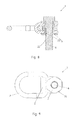
- FIG. 1 shows a stop device 1 according to the invention.
- the stop device 1 has a hanger body 2, an eyelet 3, a filler 4 and bearing bushes 5.
- the connecting device itself is penetrated in the region of the hanger body 2 by a bolt 6 and can be coupled with this bolt 6 at fastening points, not shown here, for example, on containers or the like.
- FIG. 2 shows the stop device 1 according to the invention in a side view
- the hanger body 2 is formed by a U-shape 7.
- the U-shape 7 has a valley area 8 and two legs 9 extending from the valley area 8. Between the legs 9 of the filler 4 is arranged.
- the legs 9 each have a bearing bush 5 with its collar 10 visible arranged.
- the upper portion of the bearing bush 5 is positively against the bolt head 11 and the lower collar 10 by positive engagement with a stop point not shown here.
- the eyelet 3 is arranged in a storage area 12, which is formed between the valley area 8 of the hanger body 2 and a bearing side 13 of the filling body 4.
- a clamping means 14 in the form of a compression spring is further arranged.
- FIG. 3 shows the stop device 1 according to the invention in a plan view, in which case the section line A is shown.
- FIG. 4 a cross section through the stop device 1 according to the invention along the section line A is made FIG. 3 ,
- the bushings 5 are in the illustration according to FIG. 4 arranged in the bracket body and the filler so that they come against each other at a contact point 16 for positive engagement.
- Both the hanger body 2 and the filling body 4 are rotatably mounted in the sequence about an axis of rotation 17, wherein the storage is done by the bearing bush 5 itself.
- the eyelet 3 comes in the storage area 12 of the hanger body 2 to the plant. This is done by a force applied by the tensioning means 14 on the eyelet 3 force 18.
- the diameter D of the bolt 6 is shown.
- FIG. 5 shows a sectional view along the section line B from FIG. 4 ,
- the stop device 1 is shown in a sectional view such that two clamping means 14 are arranged in blind holes 19.
- the eyelet 3 is pivotally arranged about the pivot axis 20, wherein between the pivot axis 20 and the rotation axis 17 of the hanger body 2, a distance a is formed.
- the two spring-elastic clamping means 14 have a distance b to each other. The distance b is approximately equal to each part along a central axis M of the connecting device according to the invention. A tilting of the eyelet 3 is thus largely avoided by an equal force F by the resilient tensioning means 14.
- FIG. 6 shows a same cross section through the stop device 1 according to the invention along the section line A from FIG. 3 , The difference to FIG. 4 is that between the two bushings 5, a spring washer 21 is incorporated. The spring washer 21 engages in an external thread 22 of the bolt. 6
- FIG. 7 shows an alternative embodiment to FIG. 4 with the difference that the two bushings 5 are pressed together in the contact region 16.
- FIG. 8 shows an analogous cross-sectional view through a connecting device according to the invention according to the section line A from FIG. 3 ,
- FIG. 9 shows a view of FIG. 8 from underneath. It can be seen here that an external hexagon 24 is formed on the lower bearing bush 5 with internal thread 23. Here can be arranged on a non-illustrated open-end wrench between the hanger body 2 and the mounting location not shown here, a backup of the bolt 6 done so that an accidental release of the connection device is not possible.
- FIG. 10 shows a further embodiment analogous to FIG. 4 , wherein on the bearing bushes 5, an outer circumferential shoulder 25 is formed, which rests in an inner peripheral groove 26 of the packing 4. The heel thus comes between a flank 27 on the filler 4 and a flank 28 on the hanger body 2 to the plant, so that slipping out of the bearing bush 5 from the hanger body 2 by a positional fixation is not possible.
- the system is manufactured by the spring force F, which is produced by the tensioning means 14.
Landscapes
- Engineering & Computer Science (AREA)
- Mechanical Engineering (AREA)
- Pivots And Pivotal Connections (AREA)
- Connection Of Plates (AREA)
Applications Claiming Priority (1)
| Application Number | Priority Date | Filing Date | Title |
|---|---|---|---|
| DE201010032571 DE102010032571A1 (de) | 2010-07-28 | 2010-07-28 | Flacher Verzurrpunkt |
Publications (2)
| Publication Number | Publication Date |
|---|---|
| EP2412660A1 true EP2412660A1 (fr) | 2012-02-01 |
| EP2412660B1 EP2412660B1 (fr) | 2013-11-20 |
Family
ID=44735783
Family Applications (1)
| Application Number | Title | Priority Date | Filing Date |
|---|---|---|---|
| EP11169269.5A Active EP2412660B1 (fr) | 2010-07-28 | 2011-06-09 | Point d'amarrage plat |
Country Status (2)
| Country | Link |
|---|---|
| EP (1) | EP2412660B1 (fr) |
| DE (1) | DE102010032571A1 (fr) |
Cited By (6)
| Publication number | Priority date | Publication date | Assignee | Title |
|---|---|---|---|---|
| CN103466433A (zh) * | 2013-09-09 | 2013-12-25 | 中达电机股份有限公司 | 万向吊攀 |
| LU92243B1 (fr) * | 2013-07-08 | 2015-01-09 | Intelprop Sa | Anneau de levage |
| LU92242B1 (fr) * | 2013-07-08 | 2015-01-09 | Intelprop Sa | Point de levage tournant |
| WO2015169673A1 (fr) * | 2014-05-09 | 2015-11-12 | Rud Ketten Rieger & Dietz Gmbh U. Co. Kg | Élément annulaire muni d'un socle fractionné pour un moyen d'amarrage ou d'accrochage |
| JPWO2023149177A1 (fr) * | 2022-02-03 | 2023-08-10 | ||
| LU508437B1 (en) * | 2024-10-02 | 2026-04-02 | Codiprolux S A | Swivel lifting ring assembly with an off-center eyelet |
Citations (7)
| Publication number | Priority date | Publication date | Assignee | Title |
|---|---|---|---|---|
| DE8601343U1 (de) * | 1986-01-21 | 1986-04-03 | Thiele GmbH & Co. KG, 58640 Iserlohn | Drehbarer Transportring |
| US6068310A (en) * | 1998-09-04 | 2000-05-30 | Jergens, Inc. | Hoist ring |
| DE10013845A1 (de) | 2000-03-15 | 2001-09-27 | Rud Ketten Rieger & Dietz | Anschlußvorrichtung |
| DE20121121U1 (de) * | 2001-12-21 | 2002-04-25 | RUD-Kettenfabrik Rieger & Dietz GmbH u. Co., 73432 Aalen | Anschlußvorrichtung zum Anschließen von Anschlag- oder Verzurrmitteln |
| AT412269B (de) * | 2003-08-13 | 2004-12-27 | Pewag Austria Gmbh | Anschlussvorrichtung sowie fixierelement |
| EP1840070A2 (fr) * | 2006-03-29 | 2007-10-03 | PEWAG AUSTRIA GmbH | Dispositif de liaison |
| EP1961689A1 (fr) * | 2007-02-22 | 2008-08-27 | Stamperia Carcano Giuseppe S.p.A. | Dispositif d'attache, composant, kit et procédé adaptés à la fabrication de ce dispositif |
Family Cites Families (3)
| Publication number | Priority date | Publication date | Assignee | Title |
|---|---|---|---|---|
| US4431352A (en) * | 1981-09-28 | 1984-02-14 | Andrews Gary E | Fastening device |
| DE3822690C1 (en) * | 1988-07-05 | 1990-03-08 | Thiele, August, 5860 Iserlohn, De | Stop device for hoisting, hauling or lashing means |
| DE10164598B4 (de) * | 2001-12-21 | 2006-12-14 | Rud-Kettenfabrik Rieger & Dietz Gmbh U. Co. | Anschlussvorrichtung zum Anschließen von Anschlag- oder Verzurrmitteln |
-
2010
- 2010-07-28 DE DE201010032571 patent/DE102010032571A1/de active Pending
-
2011
- 2011-06-09 EP EP11169269.5A patent/EP2412660B1/fr active Active
Patent Citations (7)
| Publication number | Priority date | Publication date | Assignee | Title |
|---|---|---|---|---|
| DE8601343U1 (de) * | 1986-01-21 | 1986-04-03 | Thiele GmbH & Co. KG, 58640 Iserlohn | Drehbarer Transportring |
| US6068310A (en) * | 1998-09-04 | 2000-05-30 | Jergens, Inc. | Hoist ring |
| DE10013845A1 (de) | 2000-03-15 | 2001-09-27 | Rud Ketten Rieger & Dietz | Anschlußvorrichtung |
| DE20121121U1 (de) * | 2001-12-21 | 2002-04-25 | RUD-Kettenfabrik Rieger & Dietz GmbH u. Co., 73432 Aalen | Anschlußvorrichtung zum Anschließen von Anschlag- oder Verzurrmitteln |
| AT412269B (de) * | 2003-08-13 | 2004-12-27 | Pewag Austria Gmbh | Anschlussvorrichtung sowie fixierelement |
| EP1840070A2 (fr) * | 2006-03-29 | 2007-10-03 | PEWAG AUSTRIA GmbH | Dispositif de liaison |
| EP1961689A1 (fr) * | 2007-02-22 | 2008-08-27 | Stamperia Carcano Giuseppe S.p.A. | Dispositif d'attache, composant, kit et procédé adaptés à la fabrication de ce dispositif |
Cited By (11)
| Publication number | Priority date | Publication date | Assignee | Title |
|---|---|---|---|---|
| LU92243B1 (fr) * | 2013-07-08 | 2015-01-09 | Intelprop Sa | Anneau de levage |
| LU92242B1 (fr) * | 2013-07-08 | 2015-01-09 | Intelprop Sa | Point de levage tournant |
| WO2015004126A1 (fr) * | 2013-07-08 | 2015-01-15 | Intelprop S.A. | Point de levage tournant |
| WO2015004124A1 (fr) * | 2013-07-08 | 2015-01-15 | Intelprop S.A. | Anneau de levage |
| CN103466433A (zh) * | 2013-09-09 | 2013-12-25 | 中达电机股份有限公司 | 万向吊攀 |
| WO2015169673A1 (fr) * | 2014-05-09 | 2015-11-12 | Rud Ketten Rieger & Dietz Gmbh U. Co. Kg | Élément annulaire muni d'un socle fractionné pour un moyen d'amarrage ou d'accrochage |
| US10131523B2 (en) | 2014-05-09 | 2018-11-20 | Rud Ketten Rieger & Dietz Gmbh U. Co. K.G. | Ring element having a divided base for a lashing or attachment means |
| JPWO2023149177A1 (fr) * | 2022-02-03 | 2023-08-10 | ||
| WO2023149177A1 (fr) * | 2022-02-03 | 2023-08-10 | 株式会社キトー | Raccord de suspension |
| JP7575849B2 (ja) | 2022-02-03 | 2024-10-30 | 株式会社キトー | 吊り金具 |
| LU508437B1 (en) * | 2024-10-02 | 2026-04-02 | Codiprolux S A | Swivel lifting ring assembly with an off-center eyelet |
Also Published As
| Publication number | Publication date |
|---|---|
| EP2412660B1 (fr) | 2013-11-20 |
| DE102010032571A1 (de) | 2012-02-02 |
Similar Documents
| Publication | Publication Date | Title |
|---|---|---|
| EP0803332B1 (fr) | Dispositif expulseur pour pousser le pivot d'une articulation de suspension et/ou d'une barre d'accouplement | |
| EP2412660B1 (fr) | Point d'amarrage plat | |
| WO2003072427A2 (fr) | Dispositif pour amarrer des conteneurs | |
| EP3167205A1 (fr) | Bloc serrure avec système de verrouillage | |
| WO2015014346A1 (fr) | Vis à œil ayant un boulon de fixation et un évidement | |
| EP3122595B1 (fr) | Dispositif d'arrimage de conteneurs | |
| DE102004020000B4 (de) | Abhängeelement | |
| EP2844601A1 (fr) | Vis à il comprenant une rondelle de glissement | |
| DE102012110208B4 (de) | Betätigungseinheit für einen Fahrzeugsitz | |
| DE202012103079U1 (de) | Anschlagöse | |
| DE19748117C2 (de) | Kugelzapfen | |
| EP3722244B1 (fr) | Anneau de levage pivotant | |
| DE102015115040A1 (de) | Trampolin | |
| EP0645216B1 (fr) | Compresseur de ressort pour ressorts de suspension MacPherson | |
| DE10236031C1 (de) | Scharnierband mit einer höheneinstellbaren Hebe-Senkvorrichtung für Türen oder Fenster | |
| EP1580073B1 (fr) | Dispositif de verrouillage pour conteneurs sur un véhicule | |
| DE602005001503T2 (de) | Schwenkvorrichtung für Scheren | |
| DE202009014301U1 (de) | Spannschraube sowie Vorrichtung zum Verzurren von Containern an Bord von Schiffen mit einer solchen Spannschraube | |
| DE102008012293A1 (de) | Spannschloss zum Festzurren von Ladungen, insbesondere auf Fahrzeugen | |
| DE102015118196A1 (de) | Vorrichtung zum lösbaren Verbinden einer Zusatzradfelge mit einer Fahrzeugradfelge und Spannstange zur Verwendung in der Vorrichtung | |
| DE202006014999U1 (de) | Federspanner für Schraubenfedern | |
| DE112006002662B4 (de) | Blattfeder mit im Querschnitt konvexer Ober-und Unterseite | |
| DE102005004943A1 (de) | Zurrvorrichtung für insbesondere an Bord von Schiffen gestaute Container sowie Verfahren und Vorrichtung zum Sichern einer solchen Zurrvorrichtung | |
| DE202008002992U1 (de) | Spannschloss zum Festzurren von Ladungen, insbesondere auf Fahrzeugen | |
| DE3630463C2 (de) | Türfeststeller, insbesondere für Kraftwagentüren |
Legal Events
| Date | Code | Title | Description |
|---|---|---|---|
| AK | Designated contracting states |
Kind code of ref document: A1 Designated state(s): AL AT BE BG CH CY CZ DE DK EE ES FI FR GB GR HR HU IE IS IT LI LT LU LV MC MK MT NL NO PL PT RO RS SE SI SK SM TR |
|
| AX | Request for extension of the european patent |
Extension state: BA ME |
|
| PUAI | Public reference made under article 153(3) epc to a published international application that has entered the european phase |
Free format text: ORIGINAL CODE: 0009012 |
|
| 17P | Request for examination filed |
Effective date: 20120126 |
|
| RIC1 | Information provided on ipc code assigned before grant |
Ipc: B66C 1/66 20060101AFI20130514BHEP |
|
| GRAP | Despatch of communication of intention to grant a patent |
Free format text: ORIGINAL CODE: EPIDOSNIGR1 |
|
| INTG | Intention to grant announced |
Effective date: 20130826 |
|
| GRAS | Grant fee paid |
Free format text: ORIGINAL CODE: EPIDOSNIGR3 |
|
| GRAA | (expected) grant |
Free format text: ORIGINAL CODE: 0009210 |
|
| AK | Designated contracting states |
Kind code of ref document: B1 Designated state(s): AL AT BE BG CH CY CZ DE DK EE ES FI FR GB GR HR HU IE IS IT LI LT LU LV MC MK MT NL NO PL PT RO RS SE SI SK SM TR |
|
| REG | Reference to a national code |
Ref country code: GB Ref legal event code: FG4D Free format text: NOT ENGLISH |
|
| REG | Reference to a national code |
Ref country code: CH Ref legal event code: EP |
|
| REG | Reference to a national code |
Ref country code: AT Ref legal event code: REF Ref document number: 641484 Country of ref document: AT Kind code of ref document: T Effective date: 20131215 |
|
| REG | Reference to a national code |
Ref country code: IE Ref legal event code: FG4D Free format text: LANGUAGE OF EP DOCUMENT: GERMAN |
|
| REG | Reference to a national code |
Ref country code: DE Ref legal event code: R096 Ref document number: 502011001669 Country of ref document: DE Effective date: 20140116 |
|
| REG | Reference to a national code |
Ref country code: NL Ref legal event code: VDEP Effective date: 20131120 |
|
| REG | Reference to a national code |
Ref country code: LT Ref legal event code: MG4D |
|
| PG25 | Lapsed in a contracting state [announced via postgrant information from national office to epo] |
Ref country code: SE Free format text: LAPSE BECAUSE OF FAILURE TO SUBMIT A TRANSLATION OF THE DESCRIPTION OR TO PAY THE FEE WITHIN THE PRESCRIBED TIME-LIMIT Effective date: 20131120 Ref country code: IS Free format text: LAPSE BECAUSE OF FAILURE TO SUBMIT A TRANSLATION OF THE DESCRIPTION OR TO PAY THE FEE WITHIN THE PRESCRIBED TIME-LIMIT Effective date: 20140320 Ref country code: NL Free format text: LAPSE BECAUSE OF FAILURE TO SUBMIT A TRANSLATION OF THE DESCRIPTION OR TO PAY THE FEE WITHIN THE PRESCRIBED TIME-LIMIT Effective date: 20131120 Ref country code: LT Free format text: LAPSE BECAUSE OF FAILURE TO SUBMIT A TRANSLATION OF THE DESCRIPTION OR TO PAY THE FEE WITHIN THE PRESCRIBED TIME-LIMIT Effective date: 20131120 Ref country code: FI Free format text: LAPSE BECAUSE OF FAILURE TO SUBMIT A TRANSLATION OF THE DESCRIPTION OR TO PAY THE FEE WITHIN THE PRESCRIBED TIME-LIMIT Effective date: 20131120 Ref country code: HR Free format text: LAPSE BECAUSE OF FAILURE TO SUBMIT A TRANSLATION OF THE DESCRIPTION OR TO PAY THE FEE WITHIN THE PRESCRIBED TIME-LIMIT Effective date: 20131120 Ref country code: NO Free format text: LAPSE BECAUSE OF FAILURE TO SUBMIT A TRANSLATION OF THE DESCRIPTION OR TO PAY THE FEE WITHIN THE PRESCRIBED TIME-LIMIT Effective date: 20140220 |
|
| PG25 | Lapsed in a contracting state [announced via postgrant information from national office to epo] |
Ref country code: LV Free format text: LAPSE BECAUSE OF FAILURE TO SUBMIT A TRANSLATION OF THE DESCRIPTION OR TO PAY THE FEE WITHIN THE PRESCRIBED TIME-LIMIT Effective date: 20131120 Ref country code: ES Free format text: LAPSE BECAUSE OF FAILURE TO SUBMIT A TRANSLATION OF THE DESCRIPTION OR TO PAY THE FEE WITHIN THE PRESCRIBED TIME-LIMIT Effective date: 20131120 Ref country code: RS Free format text: LAPSE BECAUSE OF FAILURE TO SUBMIT A TRANSLATION OF THE DESCRIPTION OR TO PAY THE FEE WITHIN THE PRESCRIBED TIME-LIMIT Effective date: 20131120 |
|
| PG25 | Lapsed in a contracting state [announced via postgrant information from national office to epo] |
Ref country code: PT Free format text: LAPSE BECAUSE OF FAILURE TO SUBMIT A TRANSLATION OF THE DESCRIPTION OR TO PAY THE FEE WITHIN THE PRESCRIBED TIME-LIMIT Effective date: 20140320 |
|
| PG25 | Lapsed in a contracting state [announced via postgrant information from national office to epo] |
Ref country code: EE Free format text: LAPSE BECAUSE OF FAILURE TO SUBMIT A TRANSLATION OF THE DESCRIPTION OR TO PAY THE FEE WITHIN THE PRESCRIBED TIME-LIMIT Effective date: 20131120 |
|
| REG | Reference to a national code |
Ref country code: DE Ref legal event code: R097 Ref document number: 502011001669 Country of ref document: DE |
|
| PG25 | Lapsed in a contracting state [announced via postgrant information from national office to epo] |
Ref country code: CZ Free format text: LAPSE BECAUSE OF FAILURE TO SUBMIT A TRANSLATION OF THE DESCRIPTION OR TO PAY THE FEE WITHIN THE PRESCRIBED TIME-LIMIT Effective date: 20131120 Ref country code: PL Free format text: LAPSE BECAUSE OF FAILURE TO SUBMIT A TRANSLATION OF THE DESCRIPTION OR TO PAY THE FEE WITHIN THE PRESCRIBED TIME-LIMIT Effective date: 20131120 Ref country code: RO Free format text: LAPSE BECAUSE OF FAILURE TO SUBMIT A TRANSLATION OF THE DESCRIPTION OR TO PAY THE FEE WITHIN THE PRESCRIBED TIME-LIMIT Effective date: 20131120 Ref country code: SK Free format text: LAPSE BECAUSE OF FAILURE TO SUBMIT A TRANSLATION OF THE DESCRIPTION OR TO PAY THE FEE WITHIN THE PRESCRIBED TIME-LIMIT Effective date: 20131120 |
|
| PLBE | No opposition filed within time limit |
Free format text: ORIGINAL CODE: 0009261 |
|
| STAA | Information on the status of an ep patent application or granted ep patent |
Free format text: STATUS: NO OPPOSITION FILED WITHIN TIME LIMIT |
|
| PG25 | Lapsed in a contracting state [announced via postgrant information from national office to epo] |
Ref country code: DK Free format text: LAPSE BECAUSE OF FAILURE TO SUBMIT A TRANSLATION OF THE DESCRIPTION OR TO PAY THE FEE WITHIN THE PRESCRIBED TIME-LIMIT Effective date: 20131120 |
|
| 26N | No opposition filed |
Effective date: 20140821 |
|
| REG | Reference to a national code |
Ref country code: DE Ref legal event code: R097 Ref document number: 502011001669 Country of ref document: DE Effective date: 20140821 |
|
| PG25 | Lapsed in a contracting state [announced via postgrant information from national office to epo] |
Ref country code: MC Free format text: LAPSE BECAUSE OF FAILURE TO SUBMIT A TRANSLATION OF THE DESCRIPTION OR TO PAY THE FEE WITHIN THE PRESCRIBED TIME-LIMIT Effective date: 20131120 Ref country code: LU Free format text: LAPSE BECAUSE OF FAILURE TO SUBMIT A TRANSLATION OF THE DESCRIPTION OR TO PAY THE FEE WITHIN THE PRESCRIBED TIME-LIMIT Effective date: 20140609 |
|
| REG | Reference to a national code |
Ref country code: CH Ref legal event code: PL |
|
| PG25 | Lapsed in a contracting state [announced via postgrant information from national office to epo] |
Ref country code: SI Free format text: LAPSE BECAUSE OF FAILURE TO SUBMIT A TRANSLATION OF THE DESCRIPTION OR TO PAY THE FEE WITHIN THE PRESCRIBED TIME-LIMIT Effective date: 20131120 |
|
| REG | Reference to a national code |
Ref country code: IE Ref legal event code: MM4A |
|
| REG | Reference to a national code |
Ref country code: FR Ref legal event code: ST Effective date: 20150227 |
|
| PG25 | Lapsed in a contracting state [announced via postgrant information from national office to epo] |
Ref country code: IE Free format text: LAPSE BECAUSE OF NON-PAYMENT OF DUE FEES Effective date: 20140609 Ref country code: LI Free format text: LAPSE BECAUSE OF NON-PAYMENT OF DUE FEES Effective date: 20140630 Ref country code: CH Free format text: LAPSE BECAUSE OF NON-PAYMENT OF DUE FEES Effective date: 20140630 |
|
| PG25 | Lapsed in a contracting state [announced via postgrant information from national office to epo] |
Ref country code: FR Free format text: LAPSE BECAUSE OF NON-PAYMENT OF DUE FEES Effective date: 20140630 |
|
| GBPC | Gb: european patent ceased through non-payment of renewal fee |
Effective date: 20150609 |
|
| PG25 | Lapsed in a contracting state [announced via postgrant information from national office to epo] |
Ref country code: MT Free format text: LAPSE BECAUSE OF FAILURE TO SUBMIT A TRANSLATION OF THE DESCRIPTION OR TO PAY THE FEE WITHIN THE PRESCRIBED TIME-LIMIT Effective date: 20131120 |
|
| PG25 | Lapsed in a contracting state [announced via postgrant information from national office to epo] |
Ref country code: GB Free format text: LAPSE BECAUSE OF NON-PAYMENT OF DUE FEES Effective date: 20150609 Ref country code: SM Free format text: LAPSE BECAUSE OF FAILURE TO SUBMIT A TRANSLATION OF THE DESCRIPTION OR TO PAY THE FEE WITHIN THE PRESCRIBED TIME-LIMIT Effective date: 20131120 |
|
| PG25 | Lapsed in a contracting state [announced via postgrant information from national office to epo] |
Ref country code: CY Free format text: LAPSE BECAUSE OF FAILURE TO SUBMIT A TRANSLATION OF THE DESCRIPTION OR TO PAY THE FEE WITHIN THE PRESCRIBED TIME-LIMIT Effective date: 20131120 Ref country code: BG Free format text: LAPSE BECAUSE OF FAILURE TO SUBMIT A TRANSLATION OF THE DESCRIPTION OR TO PAY THE FEE WITHIN THE PRESCRIBED TIME-LIMIT Effective date: 20131120 Ref country code: GR Free format text: LAPSE BECAUSE OF FAILURE TO SUBMIT A TRANSLATION OF THE DESCRIPTION OR TO PAY THE FEE WITHIN THE PRESCRIBED TIME-LIMIT Effective date: 20140221 |
|
| PG25 | Lapsed in a contracting state [announced via postgrant information from national office to epo] |
Ref country code: TR Free format text: LAPSE BECAUSE OF FAILURE TO SUBMIT A TRANSLATION OF THE DESCRIPTION OR TO PAY THE FEE WITHIN THE PRESCRIBED TIME-LIMIT Effective date: 20131120 Ref country code: BE Free format text: LAPSE BECAUSE OF FAILURE TO SUBMIT A TRANSLATION OF THE DESCRIPTION OR TO PAY THE FEE WITHIN THE PRESCRIBED TIME-LIMIT Effective date: 20140630 Ref country code: HU Free format text: LAPSE BECAUSE OF FAILURE TO SUBMIT A TRANSLATION OF THE DESCRIPTION OR TO PAY THE FEE WITHIN THE PRESCRIBED TIME-LIMIT; INVALID AB INITIO Effective date: 20110609 |
|
| PG25 | Lapsed in a contracting state [announced via postgrant information from national office to epo] |
Ref country code: MK Free format text: LAPSE BECAUSE OF FAILURE TO SUBMIT A TRANSLATION OF THE DESCRIPTION OR TO PAY THE FEE WITHIN THE PRESCRIBED TIME-LIMIT Effective date: 20131120 |
|
| PG25 | Lapsed in a contracting state [announced via postgrant information from national office to epo] |
Ref country code: AL Free format text: LAPSE BECAUSE OF FAILURE TO SUBMIT A TRANSLATION OF THE DESCRIPTION OR TO PAY THE FEE WITHIN THE PRESCRIBED TIME-LIMIT Effective date: 20131120 |
|
| PGFP | Annual fee paid to national office [announced via postgrant information from national office to epo] |
Ref country code: AT Payment date: 20230621 Year of fee payment: 13 |
|
| PGFP | Annual fee paid to national office [announced via postgrant information from national office to epo] |
Ref country code: IT Payment date: 20230623 Year of fee payment: 13 |
|
| REG | Reference to a national code |
Ref country code: AT Ref legal event code: MM01 Ref document number: 641484 Country of ref document: AT Kind code of ref document: T Effective date: 20240609 |
|
| PG25 | Lapsed in a contracting state [announced via postgrant information from national office to epo] |
Ref country code: AT Free format text: LAPSE BECAUSE OF NON-PAYMENT OF DUE FEES Effective date: 20240609 |
|
| PG25 | Lapsed in a contracting state [announced via postgrant information from national office to epo] |
Ref country code: IT Free format text: LAPSE BECAUSE OF NON-PAYMENT OF DUE FEES Effective date: 20240609 |
|
| PGFP | Annual fee paid to national office [announced via postgrant information from national office to epo] |
Ref country code: DE Payment date: 20250627 Year of fee payment: 15 |