EP2412895A2 - Fermeture pour fosse d'inspection pour autocar - Google Patents
Fermeture pour fosse d'inspection pour autocar Download PDFInfo
- Publication number
- EP2412895A2 EP2412895A2 EP20110173788 EP11173788A EP2412895A2 EP 2412895 A2 EP2412895 A2 EP 2412895A2 EP 20110173788 EP20110173788 EP 20110173788 EP 11173788 A EP11173788 A EP 11173788A EP 2412895 A2 EP2412895 A2 EP 2412895A2
- Authority
- EP
- European Patent Office
- Prior art keywords
- sliding element
- frame
- bus hatch
- bus
- covering device
- Prior art date
- Legal status (The legal status is an assumption and is not a legal conclusion. Google has not performed a legal analysis and makes no representation as to the accuracy of the status listed.)
- Granted
Links
Images


Classifications
-
- E—FIXED CONSTRUCTIONS
- E04—BUILDING
- E04H—BUILDINGS OR LIKE STRUCTURES FOR PARTICULAR PURPOSES; SWIMMING OR SPLASH BATHS OR POOLS; MASTS; FENCING; TENTS OR CANOPIES, IN GENERAL
- E04H5/00—Buildings or groups of buildings for industrial or agricultural purposes
- E04H5/02—Buildings or groups of buildings for industrial purposes, e.g. for power-plants or factories
- E04H5/06—Pits or building structures for inspection or services
Definitions
- the invention relates to a bus hatch covering device for covering a bus hatch connected to a mounting pit according to the preamble of claim 1 and to a prefabricated assembly pit according to claim 12.
- Bus hatches of the type mentioned here are known. They are connected to a mounting pit and are arranged laterally therefrom. Particularly in the case of underfloor buses, there is the problem that the internal combustion engine can usually only be removed from the underside of the bus for constructional reasons. For this purpose, a mounting or repair pit is required, as for example from the DE 20 2006 008 537 U1 is known. The bus is positioned over the mounting pit, whereupon the motor can be removed downwards. In order to subsequently remove the engine for maintenance or repair purposes, for example, from the mounting pit, at least one so-called bus hatch is provided which extends laterally of the mounting pit and can be lifted from the mounting pit, for example by means of a crane.
- bus hatch can also be used to remove other components in a blocked by a vehicle mounting pit from this.
- the bus hatch is not needed, it is provided for safety reasons with a drive-over grid or the like cover. If a motor or the like is to be removed via the bus hatch from the mounting pit, the grid or the cover must first be laboriously removed from the outside. This is associated with a considerable amount of time and effort.
- Object of the present invention is therefore to provide a Busluken cover, which can be easily and quickly operated and also offers increased safety.
- a bus hatch covering device with the features of claim 1 is proposed. It is characterized by an at least partially provided with a drive-over cover frame, which is substantially twice as long as the width of a bus hatch to be covered. Furthermore, the bus hatch covering device is characterized by a sliding element, which is movably mounted in the frame and is substantially as long as the width of a bus hatch to be covered. The sliding element is displaceable with respect to the frame into a first position in which it is arranged substantially completely in the cover-free region of the frame. In addition, the sliding element is displaceable with respect to the frame in a second position in which it is substantially completely covered by the cover.
- An essential point of the present invention consists in the fact that the guided in the frame sliding element forms a cover for a bus hatch, which in the manner of a drawer, from the interior of the mounting pit, can be easily pushed into the frame so that it - covered by the Cover of the frame - safely stowed.
- the bus hatch is then accessible in its full length and width and can be used as a work space. If the bus hatch is no longer needed, in turn, the sliding element is pulled out manually from the "SchubiadenauFddling", again from the interior of the mounting pit.
- the invention provides a particularly simple and quick operation of the Busluken cover ensures that does not require much effort, and which can be accomplished from the inside of the mounting pit.
- the sliding element is designed to be fully traversable for vehicles when the bus hatch is not in use, so the bus hatch is covered by the sliding element.
- the sliding element may comprise a frame part and support beam profiles which are detachably connected to the frame part.
- the stringer profiles can be made of aluminum, steel or plastic. Aluminum profiles are particularly advantageous because they are particularly lightweight and yet stable. Consequently, the weight of the sliding element is low.
- the sliding element preferably has at least one gripping element, by means of which the sliding element can be moved in the frame.
- a bush conveyor chain is preferably arranged, which is fastened in particular to the sliding element and which serves as a bearing.
- the bush conveyor chain can be designed ball-bearing or slide-mounted.
- an automatic warning signal device may be provided to increase safety at work, which generates a permanent visual and / or audible warning signal as long as the sliding element is removed from the first position when the bus hatch is thus opened.
- a prefabricated assembly pit which has a bus hatch cover according to the invention.
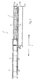
- Fig. 1 shows a section through a bus hatch covering device 1 according to the invention along a longitudinal direction L.
- the bus hatch covering device 1 comprises a frame 3, which is provided with a fully overflowable cover 5.
- the bus hatch covering device 1 comprises a sliding element 7, which is mounted movably in the frame 3 by means of a ball-bearing or slide-mounted conveying chain 9.
- the bush conveyor chain 9 is disposed between the sliding member 7 and the frame 3 and fixed to the sliding member 7.
- a Buchsen everydaykette 9 is provided on both sides of the sliding element 7 . Overall, thus two Buchens looseketten 9 are provided.
- the frame 3 does not necessarily consist of connected and interconnected parts. It is conceivable, for example, that the frame comprises only two mutually parallel support and guide profiles. It is crucial that the frame or the frame parts of the frame are provided with the cover 5 and the frame 3 and the cover 5 form a receptacle for the sliding element 7.
- the sliding element 7 is formed by a frame construction made of Spezialprofven, with the support beam profiles 11, preferably made of aluminum, are detachably connected.
- the sliding element 7 has an upper frame part 13a and a lower frame part 13b, which ensure the continuity of a side wall of a steel cassette mounting pit or a concrete pit in the closed state of the sliding element 7.
- the Fig. 1 makes it clear that the sliding element 7 by means of suitable bearings, in particular by means of the ball-bearing bush conveyor chains 9 on or in the frame is movable, so that the sliding element 7 is a first in Fig. 1 shown position in the cover-free area of the frame 3 can take. In this position, the sliding element 7 is in a closed state and the bus hatch is covered. Preferably, by manual operation, the sliding element 7 can be pushed along the frame 3 under the cover 5, so that the sliding element 7 is arranged in its second position. In this position, the sliding element 7 is in an open state. The bus hatch is freely accessible in this state, ie open at the top and can be used as a work space.
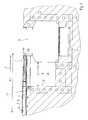
- Fig. 2 shows a cross section through a factory-prefabricated mounting pit 15 with a bus hatch cover device according to the invention 1.
- Such mounting and repair pits are known from the prior art. They consist of a usable in a bottom recess single or multi-part cassette made of steel or the like rigid and corrosion resistant material, with two longitudinal side walls 17a and 17b, arranged end, not visible here end walls and a bottom 19, wherein the walls and / or the bottom at least each partially single or double-walled with a cavity arranged therebetween for receiving hardenable filling material, such as lightweight concrete or the like, are formed.
- the side walls preferably have large-volume perforated baffles.
- Such assembly and repair pits are used by workshops or manufacturing plants for the assembly or repair of motor vehicles, rail vehicles, machinery or machine parts.
- the staff can work in a comfortable upright position under the appropriate vehicles and machines.
- Conventional assembly and repair pits are usually made on site, For this purpose, first outer and inner casing walls are placed, which are then filled with filling material, preferably with concrete.
- the setting up of these formwork or the production of conventional assembly and repair pits thus requires a possibly long employment of a variety of partially different craftsmen on site, so that high production costs incurred and long construction times occur.
- These disadvantages can be avoided by a manufacturer-prefabricated cassette made of steel or the like, which is used in a bottom recess on site.
- the bus hatch 21 extends laterally of the mounting pit and is in communication with this.
- the bus hatch 21 is preferably about 1 m wide and about 2 m long, wherein the width of the bus hatch refers to the transverse direction Q of the mounting pit 15, which corresponds to the longitudinal direction L of the bus hatch cover 1.
- the longitudinal direction of the mounting pit extends perpendicularly into the plane of the drawing.
- the mounting pit 15 is in the Fig. 2 used in a Bodenausströmung and firmly connected to the surrounding soil by means of concrete or the like material.
- the bus hatch cover 1 is arranged, which in Fig. 2 is shown in a closed state, in which the bus hatch 21 is thus covered by the sliding element 7. If the bus hatch 21 is to be used as a working space, the sliding element 7 can simply be pushed into the cavity 23 of the "drawer receptacle", which is surrounded by the frame 3 and the cover 5. When the sliding element 7 has been completely removed from the bus hatch area, that is to say is completely taken up by the rear part of the frame 3, the lower frame part 13b of the sliding element 7 preferably bears against the side wall 25 of the bus hatch 21.
- the frame 3 has a length L1 which is substantially twice as long as the width B of the bus hatch 21 to be covered.
- the frame 3 is preferably made of support and guide profiles which rest on the one hand on the extending in the transverse direction Q walls of the bus hatch 21 and on the other hand extend beyond the Buslukenmony and are preferably arranged on rails that rest directly on the ground.
- the two lateral support and guide profiles are preferably connected to each other via a U-profile 27.
- Fig. 3 shows a plan view of a bus hatch cover according to the invention 1.
- the sliding element 7 is corresponding Fig. 1 and Fig. 2 shown in a closed state, in which the bus hatch 21 is covered by the sliding element 7.
- Well recognizable in Fig. 3 are the aluminum support beam profiles 11 which extend in the transverse direction Q of the mounting pit or in the longitudinal direction L of the bus hatch cover 1 and which form a fully traversable surface.
- the cover 5 of the frame 3, which is also fully traversable extends.
- FIG. 23 shows the transition regions 31 in which the frame parts 13a and 13b continuously merge into the pit profiles 29a and 29b.
- the piling profiles 29a and 29b usually serve as a running rail for aids such as pit lifts, oil trucks, etc, which can be moved back and forth in the longitudinal direction of the mounting pit 15.
- the pit profiles 29a and 29b each protrude inward into the mounting pit.
- the bus hatch 21 causes a gap in the pit profiles, the unhindered passage through such parts with special needs.
- This disadvantage is avoided in that the face of the sliding element 7 facing the mounting pit according to the invention has an upper and a lower frame profile which correspond to the pit profiles 29a and 29b.
- the frame parts 13a and 13b are preferably attached to the frame of the sliding element 7 or to the support beam profiles 11 such that it is readily possible to drive over the profiles 13a and 13b with a pit lift loaded by a heavy weight.
- Fig. 4 shows an end view of a bus hatch cover device according to the invention 1.
- the support profiles or support beams 11 have a trapezoidal cross-section and are each divided by two longitudinal webs into three separate longitudinal chambers. This results in a particularly stable, yet lightweight construction of the support profiles.
- the support profiles are preferably detachably connected to the frame part 13 a of the rail element 7.
- Fig. 5 shows a detailed view of the bus hatch cover device according to the invention 1.
- the bush conveyor chain 9 is exemplified here ball bearing.
- the Buchsen everydaykette 9 is fixed to the underside of a U-profile 35 of the sliding element 7 and is supported on a double-T-profile 37, which is part of the frame 3.
- the bush conveyor chain 9 is thus arranged between the sliding element 7 and the frame 3.
- a further double-T-profile 39 is arranged which serves primarily for guiding the sliding element 7.
- An L-profile 33 is attached to the U-profile 35 of the sliding element 7 and engages the bush conveyor chain 9 opposite side of the double-T-profile 37, so that a secure guidance of the sliding element 7 is ensured in the frame 3.
- Fig. 6 shows a plan view of an on-site concrete pit 41 having on both sides bus hatches 43 and 43 '. On the side walls of the bus hatches each sheet metal plates 45 are arranged as a separating layer, on which the not shown here Busluken cover device 1 can be arranged. In contrast to the manufacturer Completed installation pit 15, the concrete pit 41 is made only on site in a corresponding Bodenaus fundamentalung.
- Fig. 7 shows a cross section through an on-site concrete pit with a bus hatch cover 1 of the invention.
- the bus hatch cover 1 substantially corresponds to that in the Fig. 1 to 5 Covering device shown.
- the Fig. 7 makes it clear that both bus hatches 43 and 43 'are each provided with a bus hatch cover device 1 according to the invention.
- the frame 3 is preferably arranged on rails extending in the transverse direction of the concrete pit 41 on the sheets 45 beyond the side walls of the bus hatches.
- the cover 5 is preferably formed at ground level with the bottom surrounding the mounting pit. In order to avoid stumbling, the floor surrounding the bus hatch covering device 1 may be formed slightly rising in the direction of the bus hatch covering device 1.
- bus hatch cover 1 can be used both for manufacturer prefabricated assembly pits and for on-site concrete pits by the dimensions of the bus hatch (s) of the concrete pit and the dimensions of the bus hatch cover 1 are matched.
- the width of the bus hatch covering device 1 preferably corresponds substantially to the length of the bus hatch 21 or 43 and 43 '.
- a handle may be attached, with which an operator can simply push the sliding element 7 into the frame 3 under the cover 5.
- an automatic closure may be attached to the frontal frame parts, which has lateral start-up and boundary plates.
- This automatic closure for example, have a spring mechanism and prevent unintentional opening and closing, ie an unintentional displacement of the sliding element.
- a locking of the sliding element 7 is preferably possible both in the open and in the closed position.
- the closure is preferably actuated by a handle element.
- stop elements may be arranged in order to prevent complete removal of the sliding element 7 from the frame 3.
- the end positions of the sliding element 7 are provided with proximity switches which generate an optical and / or acoustic signal when the sliding element 7 is opened in order to indicate that the bus hatch is open, ie not covered.
- That the proximity switch is preferably located in the region of the frame parts 13a, 13b and / or the pit profiles 29a, 29b.
- the warning signal can be generated for example by a red all-round light or the like.
- the warning signal indicates that the bus hatch is open for one operation. As a result, the occupational safety is considerably increased.
- the warning signal is generated until the bus hatch is completely closed and locked again, ie the sliding element 7 is again in its end position, in which, in particular, the frame parts 13a and 13b are aligned with the pit profiles 29a and 29b.
- handle member which can simultaneously serve to displace the sliding element
- it is a kind of door handle, which, when it is depressed, a spring element actuated such that the positional locking of the sliding element is released.
- the locking mechanism by the force of the spring in corresponding recesses, in particular in the side walls of the bus hatch, engage. In this way, a secure locking of the sliding element 7 is possible and precluded its unintentional displacement.
Landscapes
- Engineering & Computer Science (AREA)
- Architecture (AREA)
- Civil Engineering (AREA)
- Structural Engineering (AREA)
- Power-Operated Mechanisms For Wings (AREA)
- Connector Housings Or Holding Contact Members (AREA)
- Wing Frames And Configurations (AREA)
- Forms Removed On Construction Sites Or Auxiliary Members Thereof (AREA)
Applications Claiming Priority (1)
| Application Number | Priority Date | Filing Date | Title |
|---|---|---|---|
| DE102010036714A DE102010036714A1 (de) | 2010-07-28 | 2010-07-28 | Busluken-Abdeckeinrichtung |
Publications (3)
| Publication Number | Publication Date |
|---|---|
| EP2412895A2 true EP2412895A2 (fr) | 2012-02-01 |
| EP2412895A3 EP2412895A3 (fr) | 2015-06-24 |
| EP2412895B1 EP2412895B1 (fr) | 2017-03-15 |
Family
ID=44802600
Family Applications (1)
| Application Number | Title | Priority Date | Filing Date |
|---|---|---|---|
| EP11173788.8A Active EP2412895B1 (fr) | 2010-07-28 | 2011-07-13 | Fosse d'inspection prefabriquée |
Country Status (5)
| Country | Link |
|---|---|
| EP (1) | EP2412895B1 (fr) |
| DE (1) | DE102010036714A1 (fr) |
| DK (1) | DK2412895T3 (fr) |
| PL (1) | PL2412895T3 (fr) |
| PT (1) | PT2412895T (fr) |
Citations (1)
| Publication number | Priority date | Publication date | Assignee | Title |
|---|---|---|---|---|
| DE202006008537U1 (de) | 2006-05-26 | 2006-07-27 | Hans Balzer Gmbh & Co. Kg Werkstatt- Und Fahrzeugtechnik | Montage- und Reparaturgrube |
Family Cites Families (6)
| Publication number | Priority date | Publication date | Assignee | Title |
|---|---|---|---|---|
| CH270179A (de) * | 1949-01-14 | 1950-08-31 | Steiner Fritz | Fahrzeugreinigungs-, Reparatur- oder Montagegrube. |
| US3938621A (en) * | 1973-06-06 | 1976-02-17 | Rudolph Hafner | Vehicle servicing system |
| DE3439039A1 (de) * | 1984-10-25 | 1986-04-30 | Wolfgang 4925 Kalletal Benstein | Fertig-montagegrube |
| US5189836A (en) * | 1990-11-07 | 1993-03-02 | Alder Matt L | Automated inspection pit cover system |
| DE9202835U1 (de) * | 1992-03-04 | 1992-04-23 | Eitel, Günther, 73257 Köngen | Prüf- und/oder Arbeitsgrube |
| DE29517991U1 (de) * | 1995-11-14 | 1996-06-20 | Jacobsen, Horst, Dipl.-Ing., 88287 Grünkraut | Schiebeabdeckung für Montagegruben und sonstige Bodenöffnungen |
-
2010
- 2010-07-28 DE DE102010036714A patent/DE102010036714A1/de not_active Withdrawn
-
2011
- 2011-07-13 PT PT111737888T patent/PT2412895T/pt unknown
- 2011-07-13 DK DK11173788.8T patent/DK2412895T3/en active
- 2011-07-13 PL PL11173788T patent/PL2412895T3/pl unknown
- 2011-07-13 EP EP11173788.8A patent/EP2412895B1/fr active Active
Patent Citations (1)
| Publication number | Priority date | Publication date | Assignee | Title |
|---|---|---|---|---|
| DE202006008537U1 (de) | 2006-05-26 | 2006-07-27 | Hans Balzer Gmbh & Co. Kg Werkstatt- Und Fahrzeugtechnik | Montage- und Reparaturgrube |
Also Published As
| Publication number | Publication date |
|---|---|
| DE102010036714A1 (de) | 2012-02-02 |
| PL2412895T3 (pl) | 2017-09-29 |
| EP2412895A3 (fr) | 2015-06-24 |
| PT2412895T (pt) | 2017-06-16 |
| DK2412895T3 (en) | 2017-06-26 |
| EP2412895B1 (fr) | 2017-03-15 |
Similar Documents
| Publication | Publication Date | Title |
|---|---|---|
| EP3124703B1 (fr) | Élement de glissiere de securite d'ouverture d'urgence | |
| DE4303163C2 (de) | Prüf- und/oder Arbeitsgrube | |
| EP2531437B1 (fr) | Procédé de fabrication d'un rail de roulement et rail de roulement pour un dispositif de levage à rail de roulement | |
| EP2098662B1 (fr) | Fosse de montage et de réparation et système d'évacuation d'eaux usées des fosses de montage | |
| EP1860258B1 (fr) | Fosse de montage et de réparation | |
| EP2246502B1 (fr) | Elévateur doté d'une douille de réception adaptable | |
| EP2412895B1 (fr) | Fosse d'inspection prefabriquée | |
| DE3020744C2 (de) | Abdeckung für Großbehälter und Becken | |
| DE202010008177U1 (de) | Busluken-Abdeckeinrichtung | |
| EP2565359A2 (fr) | Porte accessible à plat | |
| DE29517991U1 (de) | Schiebeabdeckung für Montagegruben und sonstige Bodenöffnungen | |
| DE20214438U1 (de) | Hebebühne für Fahrzeuge | |
| EP3029206B1 (fr) | Dispositif de fermeture de puits en plusieurs parties | |
| WO2016045916A1 (fr) | Béquille et structure d'appui pour machine de travail | |
| EP3094527A1 (fr) | Béquille de sécurité | |
| DE2708453C3 (de) | Kastenaufbau für Fahrzeuge mit mindestens einer verschiebbaren Tür | |
| DE2302145C3 (de) | Einrichtung für eine Mehrfachgarage | |
| DE102013103195B4 (de) | Transportfahrzeug | |
| DE202019003793U1 (de) | Rahmen für eine Gleiseindeckung für eine Feste Fahrbahn und Anordnung umfassend eine Feste Fahrbahn und eine Gleiseindeckung | |
| DE3000103C2 (de) | Vorrichtung zum Führen eines Zugmittels mit mehreren das jeweilige Zugmitteltrum- ziehendes Trum und/oder Leertrum -führenden Rollen | |
| EP3674250B1 (fr) | Dispositif de fermeture ou de ponction d'un évidement de sol | |
| EP2322716B1 (fr) | Finisseuse de route | |
| AT519408A1 (de) | Überfahrbares automatisch schließendes Vertikalschott | |
| EP3228791B1 (fr) | Portail coulissant | |
| EP4282804A1 (fr) | Système d'ascenseur avec une cabine pouvant être déplacée à l'extérieur du puits |
Legal Events
| Date | Code | Title | Description |
|---|---|---|---|
| AK | Designated contracting states |
Kind code of ref document: A2 Designated state(s): AL AT BE BG CH CY CZ DE DK EE ES FI FR GB GR HR HU IE IS IT LI LT LU LV MC MK MT NL NO PL PT RO RS SE SI SK SM TR |
|
| AX | Request for extension of the european patent |
Extension state: BA ME |
|
| PUAI | Public reference made under article 153(3) epc to a published international application that has entered the european phase |
Free format text: ORIGINAL CODE: 0009012 |
|
| RAP1 | Party data changed (applicant data changed or rights of an application transferred) |
Owner name: BALZER, HANS |
|
| RIN1 | Information on inventor provided before grant (corrected) |
Inventor name: BALZER, HANS |
|
| PUAL | Search report despatched |
Free format text: ORIGINAL CODE: 0009013 |
|
| AK | Designated contracting states |
Kind code of ref document: A3 Designated state(s): AL AT BE BG CH CY CZ DE DK EE ES FI FR GB GR HR HU IE IS IT LI LT LU LV MC MK MT NL NO PL PT RO RS SE SI SK SM TR |
|
| AX | Request for extension of the european patent |
Extension state: BA ME |
|
| RIC1 | Information provided on ipc code assigned before grant |
Ipc: E04H 5/06 20060101AFI20150518BHEP |
|
| 17P | Request for examination filed |
Effective date: 20151216 |
|
| RBV | Designated contracting states (corrected) |
Designated state(s): AL AT BE BG CH CY CZ DE DK EE ES FI FR GB GR HR HU IE IS IT LI LT LU LV MC MK MT NL NO PL PT RO RS SE SI SK SM TR |
|
| 17Q | First examination report despatched |
Effective date: 20160420 |
|
| GRAP | Despatch of communication of intention to grant a patent |
Free format text: ORIGINAL CODE: EPIDOSNIGR1 |
|
| INTG | Intention to grant announced |
Effective date: 20161109 |
|
| GRAS | Grant fee paid |
Free format text: ORIGINAL CODE: EPIDOSNIGR3 |
|
| GRAA | (expected) grant |
Free format text: ORIGINAL CODE: 0009210 |
|
| AK | Designated contracting states |
Kind code of ref document: B1 Designated state(s): AL AT BE BG CH CY CZ DE DK EE ES FI FR GB GR HR HU IE IS IT LI LT LU LV MC MK MT NL NO PL PT RO RS SE SI SK SM TR |
|
| REG | Reference to a national code |
Ref country code: CH Ref legal event code: EP Ref country code: GB Ref legal event code: FG4D Free format text: NOT ENGLISH |
|
| REG | Reference to a national code |
Ref country code: IE Ref legal event code: FG4D Free format text: LANGUAGE OF EP DOCUMENT: GERMAN |
|
| REG | Reference to a national code |
Ref country code: AT Ref legal event code: REF Ref document number: 875747 Country of ref document: AT Kind code of ref document: T Effective date: 20170415 |
|
| REG | Reference to a national code |
Ref country code: DE Ref legal event code: R096 Ref document number: 502011011830 Country of ref document: DE |
|
| REG | Reference to a national code |
Ref country code: CH Ref legal event code: NV Representative=s name: FIAMMENGHI-FIAMMENGHI, CH |
|
| REG | Reference to a national code |
Ref country code: NL Ref legal event code: FP |
|
| REG | Reference to a national code |
Ref country code: PT Ref legal event code: SC4A Ref document number: 2412895 Country of ref document: PT Date of ref document: 20170616 Kind code of ref document: T Free format text: AVAILABILITY OF NATIONAL TRANSLATION Effective date: 20170606 |
|
| REG | Reference to a national code |
Ref country code: DK Ref legal event code: T3 Effective date: 20170621 |
|
| REG | Reference to a national code |
Ref country code: SE Ref legal event code: TRGR |
|
| REG | Reference to a national code |
Ref country code: LT Ref legal event code: MG4D |
|
| REG | Reference to a national code |
Ref country code: FR Ref legal event code: PLFP Year of fee payment: 7 |
|
| PG25 | Lapsed in a contracting state [announced via postgrant information from national office to epo] |
Ref country code: HR Free format text: LAPSE BECAUSE OF FAILURE TO SUBMIT A TRANSLATION OF THE DESCRIPTION OR TO PAY THE FEE WITHIN THE PRESCRIBED TIME-LIMIT Effective date: 20170315 Ref country code: GR Free format text: LAPSE BECAUSE OF FAILURE TO SUBMIT A TRANSLATION OF THE DESCRIPTION OR TO PAY THE FEE WITHIN THE PRESCRIBED TIME-LIMIT Effective date: 20170616 Ref country code: LT Free format text: LAPSE BECAUSE OF FAILURE TO SUBMIT A TRANSLATION OF THE DESCRIPTION OR TO PAY THE FEE WITHIN THE PRESCRIBED TIME-LIMIT Effective date: 20170315 |
|
| PG25 | Lapsed in a contracting state [announced via postgrant information from national office to epo] |
Ref country code: RS Free format text: LAPSE BECAUSE OF FAILURE TO SUBMIT A TRANSLATION OF THE DESCRIPTION OR TO PAY THE FEE WITHIN THE PRESCRIBED TIME-LIMIT Effective date: 20170315 Ref country code: BG Free format text: LAPSE BECAUSE OF FAILURE TO SUBMIT A TRANSLATION OF THE DESCRIPTION OR TO PAY THE FEE WITHIN THE PRESCRIBED TIME-LIMIT Effective date: 20170615 Ref country code: LV Free format text: LAPSE BECAUSE OF FAILURE TO SUBMIT A TRANSLATION OF THE DESCRIPTION OR TO PAY THE FEE WITHIN THE PRESCRIBED TIME-LIMIT Effective date: 20170315 |
|
| PGFP | Annual fee paid to national office [announced via postgrant information from national office to epo] |
Ref country code: LU Payment date: 20170725 Year of fee payment: 7 |
|
| PGFP | Annual fee paid to national office [announced via postgrant information from national office to epo] |
Ref country code: NL Payment date: 20170725 Year of fee payment: 7 |
|
| PG25 | Lapsed in a contracting state [announced via postgrant information from national office to epo] |
Ref country code: RO Free format text: LAPSE BECAUSE OF FAILURE TO SUBMIT A TRANSLATION OF THE DESCRIPTION OR TO PAY THE FEE WITHIN THE PRESCRIBED TIME-LIMIT Effective date: 20170315 Ref country code: SK Free format text: LAPSE BECAUSE OF FAILURE TO SUBMIT A TRANSLATION OF THE DESCRIPTION OR TO PAY THE FEE WITHIN THE PRESCRIBED TIME-LIMIT Effective date: 20170315 Ref country code: EE Free format text: LAPSE BECAUSE OF FAILURE TO SUBMIT A TRANSLATION OF THE DESCRIPTION OR TO PAY THE FEE WITHIN THE PRESCRIBED TIME-LIMIT Effective date: 20170315 Ref country code: NO Free format text: LAPSE BECAUSE OF FAILURE TO SUBMIT A TRANSLATION OF THE DESCRIPTION OR TO PAY THE FEE WITHIN THE PRESCRIBED TIME-LIMIT Effective date: 20170614 Ref country code: ES Free format text: LAPSE BECAUSE OF FAILURE TO SUBMIT A TRANSLATION OF THE DESCRIPTION OR TO PAY THE FEE WITHIN THE PRESCRIBED TIME-LIMIT Effective date: 20170315 Ref country code: CZ Free format text: LAPSE BECAUSE OF FAILURE TO SUBMIT A TRANSLATION OF THE DESCRIPTION OR TO PAY THE FEE WITHIN THE PRESCRIBED TIME-LIMIT Effective date: 20170315 |
|
| PGFP | Annual fee paid to national office [announced via postgrant information from national office to epo] |
Ref country code: FR Payment date: 20170727 Year of fee payment: 7 Ref country code: IT Payment date: 20170720 Year of fee payment: 7 |
|
| PG25 | Lapsed in a contracting state [announced via postgrant information from national office to epo] |
Ref country code: IS Free format text: LAPSE BECAUSE OF FAILURE TO SUBMIT A TRANSLATION OF THE DESCRIPTION OR TO PAY THE FEE WITHIN THE PRESCRIBED TIME-LIMIT Effective date: 20170715 Ref country code: SM Free format text: LAPSE BECAUSE OF FAILURE TO SUBMIT A TRANSLATION OF THE DESCRIPTION OR TO PAY THE FEE WITHIN THE PRESCRIBED TIME-LIMIT Effective date: 20170315 |
|
| PGFP | Annual fee paid to national office [announced via postgrant information from national office to epo] |
Ref country code: SE Payment date: 20170727 Year of fee payment: 7 Ref country code: BE Payment date: 20170725 Year of fee payment: 7 Ref country code: DK Payment date: 20170725 Year of fee payment: 7 |
|
| REG | Reference to a national code |
Ref country code: DE Ref legal event code: R097 Ref document number: 502011011830 Country of ref document: DE |
|
| PLBE | No opposition filed within time limit |
Free format text: ORIGINAL CODE: 0009261 |
|
| STAA | Information on the status of an ep patent application or granted ep patent |
Free format text: STATUS: NO OPPOSITION FILED WITHIN TIME LIMIT |
|
| REG | Reference to a national code |
Ref country code: DE Ref legal event code: R082 Ref document number: 502011011830 Country of ref document: DE Representative=s name: MEISSNER BOLTE PATENTANWAELTE RECHTSANWAELTE P, DE Ref country code: DE Ref legal event code: R081 Ref document number: 502011011830 Country of ref document: DE Owner name: BALZER GMBH & CO. KG, DE Free format text: FORMER OWNER: BALZER, HANS, 87700 MEMMINGEN, DE |
|
| 26N | No opposition filed |
Effective date: 20171218 |
|
| PG25 | Lapsed in a contracting state [announced via postgrant information from national office to epo] |
Ref country code: SI Free format text: LAPSE BECAUSE OF FAILURE TO SUBMIT A TRANSLATION OF THE DESCRIPTION OR TO PAY THE FEE WITHIN THE PRESCRIBED TIME-LIMIT Effective date: 20170315 |
|
| GBPC | Gb: european patent ceased through non-payment of renewal fee |
Effective date: 20170713 |
|
| REG | Reference to a national code |
Ref country code: IE Ref legal event code: MM4A |
|
| PG25 | Lapsed in a contracting state [announced via postgrant information from national office to epo] |
Ref country code: IE Free format text: LAPSE BECAUSE OF NON-PAYMENT OF DUE FEES Effective date: 20170713 Ref country code: GB Free format text: LAPSE BECAUSE OF NON-PAYMENT OF DUE FEES Effective date: 20170713 Ref country code: FI Free format text: LAPSE BECAUSE OF NON-PAYMENT OF DUE FEES Effective date: 20170713 |
|
| PG25 | Lapsed in a contracting state [announced via postgrant information from national office to epo] |
Ref country code: PT Free format text: LAPSE BECAUSE OF NON-PAYMENT OF DUE FEES Effective date: 20180413 |
|
| PG25 | Lapsed in a contracting state [announced via postgrant information from national office to epo] |
Ref country code: MT Free format text: LAPSE BECAUSE OF FAILURE TO SUBMIT A TRANSLATION OF THE DESCRIPTION OR TO PAY THE FEE WITHIN THE PRESCRIBED TIME-LIMIT Effective date: 20170315 |
|
| PG25 | Lapsed in a contracting state [announced via postgrant information from national office to epo] |
Ref country code: PL Free format text: LAPSE BECAUSE OF NON-PAYMENT OF DUE FEES Effective date: 20170713 |
|
| REG | Reference to a national code |
Ref country code: DK Ref legal event code: EBP Effective date: 20180731 |
|
| REG | Reference to a national code |
Ref country code: NL Ref legal event code: MM Effective date: 20180801 |
|
| PG25 | Lapsed in a contracting state [announced via postgrant information from national office to epo] |
Ref country code: LU Free format text: LAPSE BECAUSE OF NON-PAYMENT OF DUE FEES Effective date: 20180713 |
|
| REG | Reference to a national code |
Ref country code: BE Ref legal event code: MM Effective date: 20180731 |
|
| PG25 | Lapsed in a contracting state [announced via postgrant information from national office to epo] |
Ref country code: FR Free format text: LAPSE BECAUSE OF NON-PAYMENT OF DUE FEES Effective date: 20180731 |
|
| PG25 | Lapsed in a contracting state [announced via postgrant information from national office to epo] |
Ref country code: NL Free format text: LAPSE BECAUSE OF NON-PAYMENT OF DUE FEES Effective date: 20180801 Ref country code: SE Free format text: LAPSE BECAUSE OF NON-PAYMENT OF DUE FEES Effective date: 20180714 Ref country code: BE Free format text: LAPSE BECAUSE OF NON-PAYMENT OF DUE FEES Effective date: 20180731 |
|
| PG25 | Lapsed in a contracting state [announced via postgrant information from national office to epo] |
Ref country code: HU Free format text: LAPSE BECAUSE OF FAILURE TO SUBMIT A TRANSLATION OF THE DESCRIPTION OR TO PAY THE FEE WITHIN THE PRESCRIBED TIME-LIMIT; INVALID AB INITIO Effective date: 20110713 Ref country code: MC Free format text: LAPSE BECAUSE OF FAILURE TO SUBMIT A TRANSLATION OF THE DESCRIPTION OR TO PAY THE FEE WITHIN THE PRESCRIBED TIME-LIMIT Effective date: 20170315 |
|
| PG25 | Lapsed in a contracting state [announced via postgrant information from national office to epo] |
Ref country code: DK Free format text: LAPSE BECAUSE OF NON-PAYMENT OF DUE FEES Effective date: 20180731 Ref country code: IT Free format text: LAPSE BECAUSE OF NON-PAYMENT OF DUE FEES Effective date: 20180713 |
|
| PG25 | Lapsed in a contracting state [announced via postgrant information from national office to epo] |
Ref country code: CY Free format text: LAPSE BECAUSE OF NON-PAYMENT OF DUE FEES Effective date: 20170315 |
|
| PG25 | Lapsed in a contracting state [announced via postgrant information from national office to epo] |
Ref country code: MK Free format text: LAPSE BECAUSE OF FAILURE TO SUBMIT A TRANSLATION OF THE DESCRIPTION OR TO PAY THE FEE WITHIN THE PRESCRIBED TIME-LIMIT Effective date: 20170315 |
|
| PG25 | Lapsed in a contracting state [announced via postgrant information from national office to epo] |
Ref country code: TR Free format text: LAPSE BECAUSE OF FAILURE TO SUBMIT A TRANSLATION OF THE DESCRIPTION OR TO PAY THE FEE WITHIN THE PRESCRIBED TIME-LIMIT Effective date: 20170315 |
|
| PG25 | Lapsed in a contracting state [announced via postgrant information from national office to epo] |
Ref country code: AL Free format text: LAPSE BECAUSE OF FAILURE TO SUBMIT A TRANSLATION OF THE DESCRIPTION OR TO PAY THE FEE WITHIN THE PRESCRIBED TIME-LIMIT Effective date: 20170315 |
|
| PGFP | Annual fee paid to national office [announced via postgrant information from national office to epo] |
Ref country code: DE Payment date: 20250731 Year of fee payment: 15 |
|
| PGFP | Annual fee paid to national office [announced via postgrant information from national office to epo] |
Ref country code: AT Payment date: 20250718 Year of fee payment: 15 |
|
| PGFP | Annual fee paid to national office [announced via postgrant information from national office to epo] |
Ref country code: CH Payment date: 20250801 Year of fee payment: 15 |