EP2412979A2 - Pompe volumétrique avec rainure d'aspiration - Google Patents
Pompe volumétrique avec rainure d'aspiration Download PDFInfo
- Publication number
- EP2412979A2 EP2412979A2 EP11173969A EP11173969A EP2412979A2 EP 2412979 A2 EP2412979 A2 EP 2412979A2 EP 11173969 A EP11173969 A EP 11173969A EP 11173969 A EP11173969 A EP 11173969A EP 2412979 A2 EP2412979 A2 EP 2412979A2
- Authority
- EP
- European Patent Office
- Prior art keywords
- piston
- chamber
- pressure
- fluid
- pump
- Prior art date
- Legal status (The legal status is an assumption and is not a legal conclusion. Google has not performed a legal analysis and makes no representation as to the accuracy of the status listed.)
- Granted
Links
Images


Classifications
-
- F—MECHANICAL ENGINEERING; LIGHTING; HEATING; WEAPONS; BLASTING
- F04—POSITIVE - DISPLACEMENT MACHINES FOR LIQUIDS; PUMPS FOR LIQUIDS OR ELASTIC FLUIDS
- F04C—ROTARY-PISTON, OR OSCILLATING-PISTON, POSITIVE-DISPLACEMENT MACHINES FOR LIQUIDS; ROTARY-PISTON, OR OSCILLATING-PISTON, POSITIVE-DISPLACEMENT PUMPS
- F04C14/00—Control of, monitoring of, or safety arrangements for, machines, pumps or pumping installations
- F04C14/18—Control of, monitoring of, or safety arrangements for, machines, pumps or pumping installations characterised by varying the volume of the working chamber
- F04C14/185—Control of, monitoring of, or safety arrangements for, machines, pumps or pumping installations characterised by varying the volume of the working chamber by varying the useful pumping length of the cooperating members in the axial direction
-
- F—MECHANICAL ENGINEERING; LIGHTING; HEATING; WEAPONS; BLASTING
- F04—POSITIVE - DISPLACEMENT MACHINES FOR LIQUIDS; PUMPS FOR LIQUIDS OR ELASTIC FLUIDS
- F04C—ROTARY-PISTON, OR OSCILLATING-PISTON, POSITIVE-DISPLACEMENT MACHINES FOR LIQUIDS; ROTARY-PISTON, OR OSCILLATING-PISTON, POSITIVE-DISPLACEMENT PUMPS
- F04C2/00—Rotary-piston machines or pumps
- F04C2/08—Rotary-piston machines or pumps of intermeshing-engagement type, i.e. with engagement of co-operating members similar to that of toothed gearing
- F04C2/12—Rotary-piston machines or pumps of intermeshing-engagement type, i.e. with engagement of co-operating members similar to that of toothed gearing of other than internal-axis type
- F04C2/14—Rotary-piston machines or pumps of intermeshing-engagement type, i.e. with engagement of co-operating members similar to that of toothed gearing of other than internal-axis type with toothed rotary pistons
- F04C2/18—Rotary-piston machines or pumps of intermeshing-engagement type, i.e. with engagement of co-operating members similar to that of toothed gearing of other than internal-axis type with toothed rotary pistons with similar tooth forms
-
- F—MECHANICAL ENGINEERING; LIGHTING; HEATING; WEAPONS; BLASTING
- F04—POSITIVE - DISPLACEMENT MACHINES FOR LIQUIDS; PUMPS FOR LIQUIDS OR ELASTIC FLUIDS
- F04C—ROTARY-PISTON, OR OSCILLATING-PISTON, POSITIVE-DISPLACEMENT MACHINES FOR LIQUIDS; ROTARY-PISTON, OR OSCILLATING-PISTON, POSITIVE-DISPLACEMENT PUMPS
- F04C14/00—Control of, monitoring of, or safety arrangements for, machines, pumps or pumping installations
- F04C14/24—Control of, monitoring of, or safety arrangements for, machines, pumps or pumping installations characterised by using valves controlling pressure or flow rate, e.g. discharge valves or unloading valves
- F04C14/26—Control of, monitoring of, or safety arrangements for, machines, pumps or pumping installations characterised by using valves controlling pressure or flow rate, e.g. discharge valves or unloading valves using bypass channels
Definitions
- the invention relates to a positive displacement pump with an adjustment for their specific delivery volume.
- the pump comprises at least two rotatably mounted conveying wheels, which are in a conveying engagement with each other to promote a working fluid under pressure increase from a low pressure side of the pump to a high pressure side of the pump in a rotary drive of at least one of the conveyor wheels.
- the invention further relates to a pump comprising the system for the supply of an aggregate with a working or lubricating fluid.
- the pump is used to supply an internal combustion engine with lubricating oil, i. H. it forms with this use the lubricating oil pump of the engine.
- the specific delivery volume is understood to mean the delivery volume of the pump [delivery volume / rotational speed] which is related to the rotational speed of one of the delivery wheels.
- Positive displacement pumps are known in which one of the conveying wheels arranged in a pump chamber is displaceable along its axis of rotation and relative to the other of the conveying wheels for adjusting the volume flow.
- a piston is arranged on an end face of the feed wheel, which is displaceable together with the feed wheel and forms a sealing gap with an enclosure for the piston circumference.
- a control chamber is arranged, in which a means for generating a sliding movement of the piston is arranged.
- the invention is based on a positive displacement pump, in particular a gear pump or external gear pump.
- the pump comprises a pump chamber and a control chamber, which are separated from each other by a displaceable piston.
- a first impeller and a second impeller are arranged, wherein the impellers are preferably gears and are engaged with each other.
- the gears mesh at a combing point, d. H. Teeth of the gears mesh there.
- the gears may have an involute or cycloidal or other tooth shape known to those skilled in the art.
- the piston is preferably axially, d. H. slidable along the axis of rotation of one of the conveyor wheels, in particular of the feed wheel, which is displaceable together with the piston.
- first delivery wheel and a second delivery wheel are arranged in the pump chamber, whereby in particular only a single combing point is formed.
- a third impeller is arranged, which is either with the first impeller or with the second impeller in engagement, whereby the third impeller with the first or the second impeller can form a further Kämmstelle.
- the pump chamber comprises a suction chamber on a suction side and on a pressure side a pressure chamber, which are separated from each other by means of the intermeshing conveyor wheels.
- a suction chamber opens a feed opening, can be supplied by the fluid to be delivered from outside the pump chamber into the pump chamber.
- In the pressure chamber opens a discharge opening, by means of the fluid to be pumped from the pump chamber z. B. on the lubrication points of an aggregate, in particular motor is eligible.
- the pressure in the suction chamber is lower than in the pressure chamber.
- first impeller and a second impeller they can interlock, with only a suction chamber and only one pressure chamber is formed.
- a first, second and third impeller they can interlock at two points, so that each engagement a suction chamber and a pressure chamber is formed.
- the first impeller may be engaged with the second impeller and the second impeller may be with the third impeller.
- the two pressure chambers can be fluidly separated or connected. The same can apply to the two suction chambers.
- the advantage of connected suction chambers or pressure chambers is that the flow rate for a fluid guidance system can be increased, in particular doubled.
- suction chambers and / or pressure chambers are separate suction chambers and / or pressure chambers.
- the peripheral portion of the feed wheel which is in engagement with the two other feed wheels, can open in the circumferential direction between the engagement points in a suction chamber and in a pressure chamber.
- This conveyor wheel may in particular have two of these sections.
- the suction chamber located on one side may be separated from the pressure chamber located on the same side, z. Example by means of a wall which wraps around the second conveyor wheel over part of the circumference and forms a sealing gap with this part of the circumference.
- fluid can be conveyed from the suction chamber with a first volume flow to the pressure chamber located on the other side and with a second volume flow to the pressure chamber located on the same side.
- the conveyor wheels are - relative to the respective axes of rotation - the combing point in the opposite direction of a particular cylindrical wall of the pump chamber wrapped over part of its circumference.
- the outer diameter of the gears form a sealing gap with the walls, which partially wrap around the gears.
- the conveyor wheels are rotatable at its combing point in the direction of the suction chamber.
- the flowing in the suction space in the tooth spaces of the conveyor wheels fluid is taken in the tooth gaps and along the wrap around the pressure side, in particular in the Promoted pressure chamber.
- the engagement of the conveyor wheels at the Kämmstelle prevents the backflow of the fluid.
- an overpressure in particular based on the ambient pressure.
- the driving impeller is axially fixed in the pump.
- the driven by the driving conveyor wheel conveyor wheel can be moved along its axis of rotation, in particular shifted back and forth.
- the entrained feed wheel can take another impeller, which is preferably arranged axially fixed in the pump.
- the feed wheel is preferably displaceable, with the other two conveyor wheels, such as. B. the first and third conveyor wheels in engagement.
- the pump can promote the maximum flow.
- the volumetric flow can be reduced by displacing one delivery wheel relative to the other or the other so that the axial coverage decreases.
- the pump can promote its minimum flow.
- the displaceable feed wheel is axially fixedly connected to the piston.
- a displacement of the piston causes a displacement of the feed wheel.
- the control chamber has a preferably cylindrical wall, in which the preferably also cylindrical piston is slidably received longitudinally.
- the outer circumference of the piston forms a sealing gap with the inner circumference of the control chamber. The sealing gap is dimensioned so that the piston is axially displaceable.
- sealing gap seals the pump chamber substantially from the control chamber, but due to the required longitudinal displacement of the piston a certain clearance between the piston and wall is required, which allows a certain leakage of the sealing gap. This leakage allows the fluid to flow from the pump chamber, in particular from the pressure range, in the direction of the control chamber.
- a means is arranged, which can cause a displacement force for the piston.
- this means may be a spring, a motor or generally an actuator.
- this agent is a fluid, such as.
- As oil which has a particular varying pressure, which is preferably less than the pressure of the fluid to be delivered, in particular oil on the pressure side and greater than the pressure of the fluid to be delivered on the suction side.
- the pump according to the invention therefore has a device with which the fluid flowing out of the pump chamber in the direction of the control chamber can be discharged, preferably towards the suction side.
- the fluid flowing in the direction of the control chamber is guided or discharged to or to the suction side of the pump.
- a pressure which is lower than the pressure of the fluid on the pressure side of the pump chamber and preferably also lower than the pressure of the fluid in the control chamber.
- the suction side meets the requirements for low pressure.
- the suction side of the pump is fluidic, d. H. Fluid Siliconbar or hydraulically connected to the device.
- the device comprises a channel which is arranged in the region in which the piston forms the sealing gap with the piston guide surrounding the piston, in particular the wall of the control chamber.
- the channel could basically be arranged in the wall of the control chamber.
- the channel is arranged in the piston between the pump and control chamber. It is generally preferred that the channel is open towards the sealing gap.
- the channel can be arranged between the end faces of the piston, in particular approximately in the middle.
- the sealing gap extends from the channel in the direction Pump chamber and control chamber.
- the channel can be formed by a groove or a groove in the piston or the wall surrounding the piston.
- the channel extends at least partially preferably completely, or annularly over the circumference of the sealing gap. If the channel is arranged only partially over the circumference, it may preferably be located at a circumferential position, which is in the region of the pressure side of the pump chamber.
- the channel may be connected to the suction side or another region, in particular fluidly, which has a lower pressure than the pressure side and / or the control chamber.
- a fluid guide section open, which leads to the suction side or the side with the lower pressure, in particular into the pump chamber and / or the suction side or the suction chamber with the channel, in particular fluidly connects.
- the fluid guide section preferably also opens into the suction side or the suction chamber.
- the fluid guide section may be open or closed towards the sealing gap.
- the fluid guide section may extend approximately parallel or at least in the direction of the axis of rotation of the axially displaceable gear.
- the pressure for the fluid in the control chamber is preferably removed on the high pressure side of or after the pump. Basically, this pressure could be removed at the pressure chamber of the pump chamber.
- the pressure is preferably taken off at a point on the pressure side at which the fluid pressure corresponds as closely as possible to the fluid pressure of a consumer to be supplied by the pump with the fluid.
- the fluid pressure is preferably the pressure of the so-called main gallery, ie. H. the channel from which branch the channels for the individual lubrication points for the crankshaft and / or the camshaft.
- the piston forms a displaceable wall for the control chamber, wherein the control chamber can be acted upon with the gallery pressure.
- a valve in particular a 3/2-way valve is arranged in the fluid guide section between the gallery and the control chamber, with which the control chamber optionally fluid leading to the gallery or a reservoir is connectable.
- a valve with the same functions as a 3/2-way valve may be used, but with an additional switching position in which the valve is in a blocking position, ie an inflow of the fluid into the control chamber and an outflow of the fluid from the control chamber is locked.
- Example is a 4/3-way valve.
- the displacement of the piston may be at least supported by a spring element.
- the spring can z. B. be arranged so that they in case of failure of the scheme, such. B. the control valve, the pump by moving the piston and the displaceable feed wheel in a position for maximum flow.
- the pump may further comprise a further piston which is arranged on the side opposite the piston for the control chamber side of the feed wheel.
- the piston for the control chamber is referred to as a control piston and the opposite piston as a pressure piston.
- the pressure piston, control piston and delivery wheel can be displaced as a unit.
- the pressure piston can sealingly abut against a wall surrounding it, in particular pressure chamber wall and form a sealing gap.
- the pressure piston can have a device with which fluid flowing out of the pump chamber in the direction of the pressure chamber can be discharged.
- the explanations for the design of the fluid-removing device for the control piston also apply accordingly to the pressure piston.
- a groove may be provided on the circumference of the pressure piston, which is provided as an alternative or in addition to the fluid discharge device.
- the groove is positioned so that it connects the pressure chamber with the suction chamber with minimal overlap of the conveyor wheels or with a minimum volume flow of the pump.
- the groove which can also be referred to as a short-circuit groove, act in the manner of a bypass, which further regulates the pump with minimal flow to be pumped by passing fluid from the pressure chamber via the groove back into the suction chamber.
- the groove can open in the position for the minimum flow to the non-displaceable, ie, for example, to the first impeller out. At positions of the plunger out of position for minimal flow, the groove can be sealed by the wall surrounding the pressure piston, in particular with respect to the pressure chamber and the suction chamber.
- the pressure piston preferably has a cross section which is not rotationally symmetrical.
- the pressure piston has a circular cross-section with a circular recess which does not extend from the edge of the circular cross-section towards the center, however, to the center.
- the cross-sectional area in particular the area of the end face of the pressure piston, is smaller than the cross-sectional area of the control piston.
- the pressure piston may be motor or spring-loaded.
- the pressure piston is pressurized with a fluid, in particular with an oil, which is removed in particularly preferred embodiments on the pressure side of or after the pump. Again, it is preferable to remove the pressure from the gallery or main gallery of the engine.
- a fluid guide section may be provided for the decrease in pressure, which opens into the pressure and / or control chamber.
- the recess of the pressure piston may preferably have a distance from the center of the cross section, which corresponds to the difference between the distance of the axes of the first and second delivery wheel and the outer diameter of the first delivery wheel.
- the fluid of the control chamber and in particular also the pressure chamber from the same fluid delivery system as the fluid of the pump chamber or pump chamber and control chamber optionally also the pressure chamber are fluidly connected to each other.
- the invention further relates to a system for supplying an aggregate, preferably a piston internal combustion engine, with a working fluid or lubricating fluid, the system comprising the positive displacement pump and the unit.
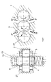
- the Figures 1 and 2 show an external gear pump with a first gear 7 and a second gear 6.
- the first gear 7 is driven by a drive such. B. the crankshaft of a motor driven (not shown). Since the first gear 7 is in a meshing engagement with the second gear 6, the second gear 6 is taken away from the rotational movement of the first gear 7.
- First and second gear 6, 7 rotate in opposite directions of rotation, so that at their Kämmstelle roll their Wälz réelle penmesser each other.
- the first gear 7 is axially bordered on both end sides by a wall of the housing 15, which form a sealing gap with the housing 15.
- the first gear 7 is looped over part of the circumference of a wall of the housing 15.
- the outer diameter of the first gear 7 and the outer surfaces of the tooth tips form a sealing gap with the housing 15.
- the second gear 6 is also looped over part of its circumference by the housing 15, whereby the outer diameter of the second gear 6, in particular the outer surfaces of its tooth tips form a sealing gap with the housing 15.
- the second gear 6 is rotatably mounted on a shaft which connects a control piston 3 and a pressure piston 13 with a defined distance from each other, which is approximately the width of the second gear 6 plus the thicknesses of the sealing gaps, which the end faces of the second gear 6 with the Control piston 3 and the pressure piston 13 form corresponds.
- the housing 15 and the pistons 3, 13 form a pump chamber 1. Below the combing point of the two gears 6, 7, a suction chamber is formed in the pump chamber and above the combing a pressure chamber.
- the pump has connections for a supply of lubricating oil to the suction chamber and for a discharge of the lubricating oil from the pressure chamber in the direction of the engine.
- the control piston 3 has a circular cross-section and is slidably received in a control chamber 2.
- the outer circumference of the cylindrical control piston 3 forms a sealing gap 8 with the correspondingly cylindrical inner circumference of the control chamber 2.
- the diameter of the control piston 3 corresponds approximately to the outer diameter of the second gear 6.
- a pressure piston 13 On the opposite side of the control piston 3 of the second gear 6 is a pressure piston 13 which is arranged along the axis of rotation of the second gear 6 slidably in a pressure chamber 9.
- the outer circumference of the pressure piston 13 forms with the wall of the pressure chamber 9 a sealing gap 17.
- the pressure piston 13 is cylindrical over most of its circumference and has an outer diameter which corresponds approximately to the outer diameter of the second gear 6.
- the pressure piston 13 has a part-cylindrical recess 14 with a radius which corresponds approximately to the radius of the outer diameter of the first gear 7, wherein the recess 14 extends from the peripheral side to the central axis of the piston 13.
- the distance of the recess 14 from the central axis of the pressure piston 13 or the axis of rotation of the second gear 6 is approximately the distance between the axes of rotation of the first and second gear 6, 7 minus the radius of the outer diameter of the first gear 7.
- the recess 14 allows in the FIGS. 3 and 4 separately shown unit of pressure piston 13, second gear 6 and control piston 3 from the in FIG. 1 shown maximum conveying position, in which the first and second gear 6, 7 are in complete axial overlap, in an in FIG. 2 to move shown minimum conveying position, in which the first and second gear 6, 7 only partially overlap axially.
- the recess 14 forms with the in FIG. 2 shown position a sealing gap with the outer diameter or the outer surfaces of the tooth tips of the first gear. 7
- the pressure piston 13 has, in particular at its cylindrical outer diameter, a groove 18, which can also be referred to as a short-circuit groove or bypass channel.
- the groove 18 extends in the circumferential direction of the cylindrical portion of the pressure piston 13.
- the groove 18 is, as in the Figures 1 and 2 can be seen, circumferentially from the wall, which forms the sealing gap 17 with the pressure piston 13, sealed.
- the cylindrical outer diameter of the pressure piston 13 forms a sealing gap 17 with the wall.
- the wall is formed by the housing 15.
- the groove 18 opens to the recess 14 through openings 19d, 19s.
- the openings 19d, 19s are arranged so that one of these openings 19d can be displaced into the pressure space and the other of the openings 19s into the suction space.
- the openings 19 d, 19 s are sealed in most of the conveying positions, in particular in the maximum conveying position of the second gear 6 of the piston 13 of the leading wall of the housing 15 ( FIG. 1 ).
- the position of the second gear 6 for a minimum volume flow of the pressure piston 13 is shifted so far that the groove 18, in particular their openings 19 d, 19 s from the seal with the housing 15, whereby the openings 19 d, 19 s to the first gear open out.
- One of the openings 19d opens into the pressure chamber, the other of the openings 19s opens into the suction chamber.
- the pressure piston 13 and the control piston 3 have discharge pockets 16 at their end faces facing the second gear wheel 6, which provide better pressure distribution in the oil during the delivery operation.
- the pressure chamber 9 is preferably permanently subjected to a pressure corresponding to the pressure from the main gallery of the engine.
- the main gallery of the engine is fluid-conducting connected to a feeder 10 and the pressure chamber 9.
- the fluid or oil contained in the pressure chamber 9 exerts a force on the pressure piston 13 which depends on the end face of the pressure piston 13 facing the pressure chamber 9.
- the pressure chamber 9 is permanently acted upon by the pressure from the main gallery of the engine.
- the control chamber 2 is also acted upon by a pressure, preferably the pressure from the main gallery of the engine. Through the supply 11, the amount of fluid contained in the control chamber or the pressure can be varied. Through the supply 11 of the control chamber 2 fluid supplied or fluid can be removed.
- the fluid supply and discharge can be controlled by a valve 12, which has 3 connections and 2 switching positions in the example shown, which is why it can be referred to as a 3/2-way valve.
- the control chamber 2 is fluid leading to the main gallery ( Fig. 1 ) or connectable to a storage container ( Fig. 2 ).
- a channel 8 open towards the sealing gap is introduced into the control piston 3.
- the channel 4 is arranged so that there is a respective sealing gap between it and the end faces of the control piston 3.
- the channel 4 may be arranged approximately centrally between the two end faces.
- the channel 4 extends annularly over the particular entire circumference of the cylindrical control piston third
- the channel 4 is connected by means of a fluid guide section 5 with the pump chamber 1, in particular with the suction chamber or the suction side.
- the leakage oil flowing over the sealing gap 8 is intercepted and via the fluid guide section 5 guided into the pump chamber 1.
- the in FIG. 3 shown fluid guide portion 5 extends approximately parallel to the axis of rotation of the second gear 6 and is open to the sealing gap 8. How out FIG. 3 In the discharge pocket 16, which is arranged in particular in the suction region, a relatively constant pressure prevails, ie that pressure fluctuations exerted on the fluid by the toothing of the rotating delivery wheel 6 are less pronounced or reduced.
- FIG. 5 a further embodiment of the invention is shown.
- the pump includes, in addition to the first gear 7 and the second gear 6, a third gear 27.
- the second gear 6 is engaged with both the first gear 7 and the third gear 27 in meshing engagement.
- a suction chamber and a pressure chamber is formed, which are separated by means of the Kämmstelle of each other, ie lying opposite.
- a pressure chamber is arranged next to the suction chamber, which are separated from each other without a comb, such. B. by means of a wall which forms a sealing gap with the circumference of the gear 6.
- fluid from the meshing gears 6, 27; 6, 7 are conveyed both to the opposite pressure chamber and to the adjoining pressure chamber.
- fluid from the suction chamber which opens to the meshing point of the second and third gear 6, 27, with a partial flow via the third gear 27 to the opposite pressure chamber, which opens to the meshing point of the gears 6, 27, and with another Partial flow via the second gear 6 to the adjacent pressure chamber, which opens to the meshing point of the first and second gear 6, 7 promoted.
- the first gear 7 and the third gear 27 may be substantially axially fixedly received in the housing, while the second gear 6 is axially displaceable relative to the first and third gear 7, 27, as in the plan view FIG. 5 indicated by the arrow direction.
- the pressure piston 13 is opposite to in the FIGS. 1 to 4 changed execution shown.
- the pressure piston 13 has two mutually opposite recesses, which like the recess 14 from the FIGS. 3 and 4 are designed.
- the pressure piston 13 has a recess 14 for the first gear 7 and on the circumference opposite a further second recess for the third gear 27.
- the grooves 18 open with their openings 19 in the position for the minimum flow in the juxtaposed Saugund pressure chambers.
- fluid can be removed from the pressure chamber opening onto the combing point 6, 7 via the groove 18 to the suction space opening onto the combing point 6, 27.
- Fluid from the pressure chamber opening into the combing point 6, 27 can be removed via a further groove 18 into the suction space opening onto the combing point 6, 7.
- FIG. 6 shows a circuit diagram with a 3/2-way valve 12 and one of the pumps described herein.
- the unit of pressure piston 13, second gear 6 and control piston 3 is shown as a sliding wall, which is acted upon by a spring which is arranged in the control chamber 2 and acts as a compression spring, with a force.
- the spring pushes the unit 13, 6, 3 in the absence of an external force in the position for a maximum flow ( FIG. 1 ).
- FIG. 6 shown switching position, in addition to the spring force, the unit 13, 6, 3 pressed into the position for the maximum flow, on the one hand because of the spring force and on the other hand because of the opposite the pressure piston 13 enlarged cross-sectional area of the control piston 3.
- the pressure chamber 9 is via the feeder 10 with subjected to the same pressure as the control chamber 2.
- z. B. electrical and / or magnetic actuation of the valve 12 this is brought against the pressure of a return spring in its second switching position, whereby the fluid of the control chamber 2 in the reservoir, such. B. an oil pan is returned. Since the force of the spring in the control chamber 2 is less than that through the pressure permanently applied to the pressure chamber 9 pressure, the unit 13, 6, 3 in the in FIG. 2 moved position shown for minimum flow.
- FIG. 7 shows a circuit diagram with a 4/3-way valve 22 and one of the pumps described herein.
- the unit 13, 6, 3 is moved to a position for a maximum flow, due to the force of the arranged in the control chamber 2 spring and the fluid pressure in the control chamber 2.
- the pressure chamber 9 is depressurized.
- the fluid of the pressure chamber 9 is guided into the reservoir.
- the terminals of the valve 22 are blocked, so that the unit 13, 6, 3 z. B. can be blocked in an intermediate position between the positions for a maximum and minimum flow.
- the unit 13, 6, 3 in the in FIG. 2 shown pressed position since the force of the spring is less than the force exerted by the pressure in the chamber 9 to the unit 13, 6, 3 compressive force.
- the fluid from the control chamber 2 is guided into the reservoir.
Landscapes
- Engineering & Computer Science (AREA)
- Mechanical Engineering (AREA)
- General Engineering & Computer Science (AREA)
- Rotary Pumps (AREA)
- Details And Applications Of Rotary Liquid Pumps (AREA)
- Details Of Reciprocating Pumps (AREA)
Priority Applications (1)
| Application Number | Priority Date | Filing Date | Title |
|---|---|---|---|
| PL11173969T PL2412979T3 (pl) | 2010-07-26 | 2011-07-14 | Pompa wyporowa z rowkiem wyciągowym |
Applications Claiming Priority (1)
| Application Number | Priority Date | Filing Date | Title |
|---|---|---|---|
| DE102010038430A DE102010038430B4 (de) | 2010-07-26 | 2010-07-26 | Verdrängerpumpe mit Absaugnut |
Publications (3)
| Publication Number | Publication Date |
|---|---|
| EP2412979A2 true EP2412979A2 (fr) | 2012-02-01 |
| EP2412979A3 EP2412979A3 (fr) | 2013-05-29 |
| EP2412979B1 EP2412979B1 (fr) | 2017-08-30 |
Family
ID=44584010
Family Applications (1)
| Application Number | Title | Priority Date | Filing Date |
|---|---|---|---|
| EP11173969.4A Not-in-force EP2412979B1 (fr) | 2010-07-26 | 2011-07-14 | Pompe volumétrique avec rainure d'aspiration |
Country Status (6)
| Country | Link |
|---|---|
| US (1) | US8899951B2 (fr) |
| EP (1) | EP2412979B1 (fr) |
| CN (1) | CN102345600B (fr) |
| DE (1) | DE102010038430B4 (fr) |
| HU (1) | HUE036123T2 (fr) |
| PL (1) | PL2412979T3 (fr) |
Cited By (1)
| Publication number | Priority date | Publication date | Assignee | Title |
|---|---|---|---|---|
| EP2479434A3 (fr) * | 2011-01-22 | 2013-05-29 | Volkswagen Aktiengesellschaft | Règlement pour une pompe à engrenages externes |
Families Citing this family (2)
| Publication number | Priority date | Publication date | Assignee | Title |
|---|---|---|---|---|
| US10989190B2 (en) * | 2015-12-04 | 2021-04-27 | Audi Ag | External gear pump |
| US10113546B2 (en) | 2016-08-16 | 2018-10-30 | Caterpillar Inc. | Pump for an engine |
Family Cites Families (12)
| Publication number | Priority date | Publication date | Assignee | Title |
|---|---|---|---|---|
| US2526830A (en) * | 1945-06-22 | 1950-10-24 | Hpm Dev Corp | Variable delivery gear pump |
| DE2506744A1 (de) * | 1975-02-18 | 1976-08-26 | Carl Dipl Kfm Kanis | Regelbare zahnradpumpen |
| DE3528651A1 (de) | 1985-08-09 | 1987-02-19 | Rohs Hans Guenther Prof Dr Ing | Zahnradpumpe |
| CN1055795A (zh) * | 1990-04-15 | 1991-10-30 | 河北机电学院 | 变量齿轮式液压系统能量转换机构 |
| CN2221117Y (zh) * | 1995-04-25 | 1996-02-28 | 丁万荣 | 变量齿轮式液压系统能量转换机构 |
| DE10222131C5 (de) * | 2002-05-17 | 2011-08-11 | Schwäbische Hüttenwerke Automotive GmbH & Co. KG, 73433 | Verdrängerpumpe mit Fördervolumenverstellung |
| AT413140B (de) | 2003-03-28 | 2005-11-15 | Tcg Unitech Ag | Zahnradpumpe |
| DE102005029086B4 (de) | 2005-06-23 | 2016-06-16 | Dr. Ing. H.C. F. Porsche Aktiengesellschaft | Ölpumpe für eine Brennkraftmaschine |
| DE102006018124A1 (de) * | 2006-04-19 | 2007-10-25 | Schwäbische Hüttenwerke Automotive GmbH & Co. KG | Verstellbare Rotationspumpe mit Verschleißminderung |
| DE102007033146B4 (de) * | 2007-07-13 | 2012-02-02 | Schwäbische Hüttenwerke Automotive GmbH & Co. KG | Verstellventil für die Verstellung des Fördervolumens einer Verdrängerpumpe |
| DE102008025346B4 (de) * | 2008-05-27 | 2019-01-17 | Audi Ag | Nutunterbrechung Regelkolben |
| CN101571122B (zh) * | 2009-05-21 | 2010-11-17 | 叶立平 | 液压圆台齿轮泵 |
-
2010
- 2010-07-26 DE DE102010038430A patent/DE102010038430B4/de active Active
-
2011
- 2011-07-14 EP EP11173969.4A patent/EP2412979B1/fr not_active Not-in-force
- 2011-07-14 HU HUE11173969A patent/HUE036123T2/hu unknown
- 2011-07-14 PL PL11173969T patent/PL2412979T3/pl unknown
- 2011-07-22 CN CN201110205851.6A patent/CN102345600B/zh active Active
- 2011-07-26 US US13/190,518 patent/US8899951B2/en not_active Expired - Fee Related
Non-Patent Citations (1)
| Title |
|---|
| None |
Cited By (1)
| Publication number | Priority date | Publication date | Assignee | Title |
|---|---|---|---|---|
| EP2479434A3 (fr) * | 2011-01-22 | 2013-05-29 | Volkswagen Aktiengesellschaft | Règlement pour une pompe à engrenages externes |
Also Published As
| Publication number | Publication date |
|---|---|
| DE102010038430B4 (de) | 2012-12-06 |
| US20120020825A1 (en) | 2012-01-26 |
| EP2412979B1 (fr) | 2017-08-30 |
| US8899951B2 (en) | 2014-12-02 |
| HUE036123T2 (hu) | 2018-06-28 |
| EP2412979A3 (fr) | 2013-05-29 |
| CN102345600B (zh) | 2016-08-03 |
| DE102010038430A8 (de) | 2012-03-29 |
| PL2412979T3 (pl) | 2018-01-31 |
| DE102010038430A1 (de) | 2012-01-26 |
| CN102345600A (zh) | 2012-02-08 |
Similar Documents
| Publication | Publication Date | Title |
|---|---|---|
| EP2732165B1 (fr) | Compresseur à vis | |
| DE102012214503B4 (de) | Rotationspumpe mit verstellbarem Fördervolumen, insbesondere zum Verstellen einer Kühlmittelpumpe | |
| DE4310518C1 (de) | Zahnradpumpe zum Fördern eines fließfähigen Mediums | |
| DE2637263A1 (de) | Rotorverdraengermaschine mit einer schnecke | |
| DE2134994A1 (de) | Zweistufige außenachsige Drehkolbenma schine fur elastische Arbeitsmedien | |
| DE4308506A1 (de) | Ölpumpensystem | |
| EP2743506A2 (fr) | Pompe à gaz dotée d'une rainure à huile d'étanchéification | |
| EP2412979B1 (fr) | Pompe volumétrique avec rainure d'aspiration | |
| DE69223919T2 (de) | Stufenlos regelbares Getriebe mit Drehkolbenpumpe | |
| EP3532728A1 (fr) | Pompe à piston rotatif munie d'une garniture d'étanchéité à chambre de barrage | |
| EP0561304B1 (fr) | Pompe à engrenages avec contrôle de l'aspiration | |
| DE4421255C1 (de) | Füllstücklose Innenzahnradpumpe | |
| DE102013202917A1 (de) | Zahnradmaschine mit erhöhter Partikelrobustheit | |
| DE1503309A1 (de) | Zahnradmotor | |
| EP0846861A1 (fr) | Pompe annulaire à engrenages continuellement variable | |
| DE102010040300B4 (de) | Geometrie eines Bypasskanals einer Verdrängerpumpe | |
| DE102019127388A1 (de) | Fluidversorgung von Unterflügelkammern einer Flügelzellenpumpe | |
| DE102010040302B4 (de) | Öffnungszeitpunkt eines Bypasskanals einer Verdrängerpumpe | |
| AT500629B1 (de) | Zahnradpumpe | |
| DE102010005072A1 (de) | Innenzahnradpumpe mit druckentlastetem Wellendichtring | |
| EP4043727B1 (fr) | Soupape de commande optimisée au niveau de la section transversale | |
| DE102014207070B4 (de) | Pumpe | |
| EP1509698A1 (fr) | Pompe a engrenages interieurs a debit volumetrique variable | |
| DE102010005984B4 (de) | Regelölpumpe | |
| DE102010049439A1 (de) | Außenzahnradpumpe |
Legal Events
| Date | Code | Title | Description |
|---|---|---|---|
| AK | Designated contracting states |
Kind code of ref document: A2 Designated state(s): AL AT BE BG CH CY CZ DE DK EE ES FI FR GB GR HR HU IE IS IT LI LT LU LV MC MK MT NL NO PL PT RO RS SE SI SK SM TR |
|
| AX | Request for extension of the european patent |
Extension state: BA ME |
|
| PUAI | Public reference made under article 153(3) epc to a published international application that has entered the european phase |
Free format text: ORIGINAL CODE: 0009012 |
|
| PUAL | Search report despatched |
Free format text: ORIGINAL CODE: 0009013 |
|
| AK | Designated contracting states |
Kind code of ref document: A3 Designated state(s): AL AT BE BG CH CY CZ DE DK EE ES FI FR GB GR HR HU IE IS IT LI LT LU LV MC MK MT NL NO PL PT RO RS SE SI SK SM TR |
|
| AX | Request for extension of the european patent |
Extension state: BA ME |
|
| RIC1 | Information provided on ipc code assigned before grant |
Ipc: F04C 18/18 20060101AFI20130419BHEP Ipc: F04C 14/26 20060101ALI20130419BHEP Ipc: F04C 14/18 20060101ALI20130419BHEP Ipc: F04C 2/18 20060101ALI20130419BHEP Ipc: F04C 28/18 20060101ALI20130419BHEP |
|
| 17P | Request for examination filed |
Effective date: 20131031 |
|
| RBV | Designated contracting states (corrected) |
Designated state(s): AL AT BE BG CH CY CZ DE DK EE ES FI FR GB GR HR HU IE IS IT LI LT LU LV MC MK MT NL NO PL PT RO RS SE SI SK SM TR |
|
| 17Q | First examination report despatched |
Effective date: 20160129 |
|
| GRAP | Despatch of communication of intention to grant a patent |
Free format text: ORIGINAL CODE: EPIDOSNIGR1 |
|
| INTG | Intention to grant announced |
Effective date: 20170320 |
|
| GRAS | Grant fee paid |
Free format text: ORIGINAL CODE: EPIDOSNIGR3 |
|
| GRAA | (expected) grant |
Free format text: ORIGINAL CODE: 0009210 |
|
| AK | Designated contracting states |
Kind code of ref document: B1 Designated state(s): AL AT BE BG CH CY CZ DE DK EE ES FI FR GB GR HR HU IE IS IT LI LT LU LV MC MK MT NL NO PL PT RO RS SE SI SK SM TR |
|
| REG | Reference to a national code |
Ref country code: GB Ref legal event code: FG4D Free format text: NOT ENGLISH |
|
| REG | Reference to a national code |
Ref country code: CH Ref legal event code: EP |
|
| REG | Reference to a national code |
Ref country code: AT Ref legal event code: REF Ref document number: 923832 Country of ref document: AT Kind code of ref document: T Effective date: 20170915 |
|
| REG | Reference to a national code |
Ref country code: IE Ref legal event code: FG4D Free format text: LANGUAGE OF EP DOCUMENT: GERMAN |
|
| REG | Reference to a national code |
Ref country code: DE Ref legal event code: R096 Ref document number: 502011012889 Country of ref document: DE |
|
| REG | Reference to a national code |
Ref country code: NL Ref legal event code: MP Effective date: 20170830 |
|
| REG | Reference to a national code |
Ref country code: LT Ref legal event code: MG4D |
|
| PG25 | Lapsed in a contracting state [announced via postgrant information from national office to epo] |
Ref country code: FI Free format text: LAPSE BECAUSE OF FAILURE TO SUBMIT A TRANSLATION OF THE DESCRIPTION OR TO PAY THE FEE WITHIN THE PRESCRIBED TIME-LIMIT Effective date: 20170830 Ref country code: SE Free format text: LAPSE BECAUSE OF FAILURE TO SUBMIT A TRANSLATION OF THE DESCRIPTION OR TO PAY THE FEE WITHIN THE PRESCRIBED TIME-LIMIT Effective date: 20170830 Ref country code: HR Free format text: LAPSE BECAUSE OF FAILURE TO SUBMIT A TRANSLATION OF THE DESCRIPTION OR TO PAY THE FEE WITHIN THE PRESCRIBED TIME-LIMIT Effective date: 20170830 Ref country code: NO Free format text: LAPSE BECAUSE OF FAILURE TO SUBMIT A TRANSLATION OF THE DESCRIPTION OR TO PAY THE FEE WITHIN THE PRESCRIBED TIME-LIMIT Effective date: 20171130 Ref country code: LT Free format text: LAPSE BECAUSE OF FAILURE TO SUBMIT A TRANSLATION OF THE DESCRIPTION OR TO PAY THE FEE WITHIN THE PRESCRIBED TIME-LIMIT Effective date: 20170830 |
|
| PG25 | Lapsed in a contracting state [announced via postgrant information from national office to epo] |
Ref country code: ES Free format text: LAPSE BECAUSE OF FAILURE TO SUBMIT A TRANSLATION OF THE DESCRIPTION OR TO PAY THE FEE WITHIN THE PRESCRIBED TIME-LIMIT Effective date: 20170830 Ref country code: RS Free format text: LAPSE BECAUSE OF FAILURE TO SUBMIT A TRANSLATION OF THE DESCRIPTION OR TO PAY THE FEE WITHIN THE PRESCRIBED TIME-LIMIT Effective date: 20170830 Ref country code: LV Free format text: LAPSE BECAUSE OF FAILURE TO SUBMIT A TRANSLATION OF THE DESCRIPTION OR TO PAY THE FEE WITHIN THE PRESCRIBED TIME-LIMIT Effective date: 20170830 Ref country code: IS Free format text: LAPSE BECAUSE OF FAILURE TO SUBMIT A TRANSLATION OF THE DESCRIPTION OR TO PAY THE FEE WITHIN THE PRESCRIBED TIME-LIMIT Effective date: 20171230 Ref country code: GR Free format text: LAPSE BECAUSE OF FAILURE TO SUBMIT A TRANSLATION OF THE DESCRIPTION OR TO PAY THE FEE WITHIN THE PRESCRIBED TIME-LIMIT Effective date: 20171201 Ref country code: BG Free format text: LAPSE BECAUSE OF FAILURE TO SUBMIT A TRANSLATION OF THE DESCRIPTION OR TO PAY THE FEE WITHIN THE PRESCRIBED TIME-LIMIT Effective date: 20171130 |
|
| PG25 | Lapsed in a contracting state [announced via postgrant information from national office to epo] |
Ref country code: NL Free format text: LAPSE BECAUSE OF FAILURE TO SUBMIT A TRANSLATION OF THE DESCRIPTION OR TO PAY THE FEE WITHIN THE PRESCRIBED TIME-LIMIT Effective date: 20170830 |
|
| PG25 | Lapsed in a contracting state [announced via postgrant information from national office to epo] |
Ref country code: DK Free format text: LAPSE BECAUSE OF FAILURE TO SUBMIT A TRANSLATION OF THE DESCRIPTION OR TO PAY THE FEE WITHIN THE PRESCRIBED TIME-LIMIT Effective date: 20170830 Ref country code: CZ Free format text: LAPSE BECAUSE OF FAILURE TO SUBMIT A TRANSLATION OF THE DESCRIPTION OR TO PAY THE FEE WITHIN THE PRESCRIBED TIME-LIMIT Effective date: 20170830 Ref country code: RO Free format text: LAPSE BECAUSE OF FAILURE TO SUBMIT A TRANSLATION OF THE DESCRIPTION OR TO PAY THE FEE WITHIN THE PRESCRIBED TIME-LIMIT Effective date: 20170830 |
|
| PG25 | Lapsed in a contracting state [announced via postgrant information from national office to epo] |
Ref country code: SK Free format text: LAPSE BECAUSE OF FAILURE TO SUBMIT A TRANSLATION OF THE DESCRIPTION OR TO PAY THE FEE WITHIN THE PRESCRIBED TIME-LIMIT Effective date: 20170830 Ref country code: SM Free format text: LAPSE BECAUSE OF FAILURE TO SUBMIT A TRANSLATION OF THE DESCRIPTION OR TO PAY THE FEE WITHIN THE PRESCRIBED TIME-LIMIT Effective date: 20170830 Ref country code: EE Free format text: LAPSE BECAUSE OF FAILURE TO SUBMIT A TRANSLATION OF THE DESCRIPTION OR TO PAY THE FEE WITHIN THE PRESCRIBED TIME-LIMIT Effective date: 20170830 Ref country code: IT Free format text: LAPSE BECAUSE OF FAILURE TO SUBMIT A TRANSLATION OF THE DESCRIPTION OR TO PAY THE FEE WITHIN THE PRESCRIBED TIME-LIMIT Effective date: 20170830 |
|
| REG | Reference to a national code |
Ref country code: DE Ref legal event code: R097 Ref document number: 502011012889 Country of ref document: DE |
|
| REG | Reference to a national code |
Ref country code: HU Ref legal event code: AG4A Ref document number: E036123 Country of ref document: HU |
|
| PLBE | No opposition filed within time limit |
Free format text: ORIGINAL CODE: 0009261 |
|
| STAA | Information on the status of an ep patent application or granted ep patent |
Free format text: STATUS: NO OPPOSITION FILED WITHIN TIME LIMIT |
|
| REG | Reference to a national code |
Ref country code: FR Ref legal event code: PLFP Year of fee payment: 8 |
|
| 26N | No opposition filed |
Effective date: 20180531 |
|
| PG25 | Lapsed in a contracting state [announced via postgrant information from national office to epo] |
Ref country code: SI Free format text: LAPSE BECAUSE OF FAILURE TO SUBMIT A TRANSLATION OF THE DESCRIPTION OR TO PAY THE FEE WITHIN THE PRESCRIBED TIME-LIMIT Effective date: 20170830 |
|
| PG25 | Lapsed in a contracting state [announced via postgrant information from national office to epo] |
Ref country code: MT Free format text: LAPSE BECAUSE OF FAILURE TO SUBMIT A TRANSLATION OF THE DESCRIPTION OR TO PAY THE FEE WITHIN THE PRESCRIBED TIME-LIMIT Effective date: 20170830 |
|
| REG | Reference to a national code |
Ref country code: CH Ref legal event code: PL |
|
| PG25 | Lapsed in a contracting state [announced via postgrant information from national office to epo] |
Ref country code: MC Free format text: LAPSE BECAUSE OF FAILURE TO SUBMIT A TRANSLATION OF THE DESCRIPTION OR TO PAY THE FEE WITHIN THE PRESCRIBED TIME-LIMIT Effective date: 20170830 Ref country code: LU Free format text: LAPSE BECAUSE OF NON-PAYMENT OF DUE FEES Effective date: 20180714 |
|
| REG | Reference to a national code |
Ref country code: BE Ref legal event code: MM Effective date: 20180731 |
|
| REG | Reference to a national code |
Ref country code: IE Ref legal event code: MM4A |
|
| PG25 | Lapsed in a contracting state [announced via postgrant information from national office to epo] |
Ref country code: CH Free format text: LAPSE BECAUSE OF NON-PAYMENT OF DUE FEES Effective date: 20180731 Ref country code: LI Free format text: LAPSE BECAUSE OF NON-PAYMENT OF DUE FEES Effective date: 20180731 Ref country code: IE Free format text: LAPSE BECAUSE OF NON-PAYMENT OF DUE FEES Effective date: 20180714 |
|
| PG25 | Lapsed in a contracting state [announced via postgrant information from national office to epo] |
Ref country code: BE Free format text: LAPSE BECAUSE OF NON-PAYMENT OF DUE FEES Effective date: 20180731 |
|
| REG | Reference to a national code |
Ref country code: AT Ref legal event code: MM01 Ref document number: 923832 Country of ref document: AT Kind code of ref document: T Effective date: 20180714 |
|
| PG25 | Lapsed in a contracting state [announced via postgrant information from national office to epo] |
Ref country code: AT Free format text: LAPSE BECAUSE OF NON-PAYMENT OF DUE FEES Effective date: 20180714 |
|
| PG25 | Lapsed in a contracting state [announced via postgrant information from national office to epo] |
Ref country code: TR Free format text: LAPSE BECAUSE OF FAILURE TO SUBMIT A TRANSLATION OF THE DESCRIPTION OR TO PAY THE FEE WITHIN THE PRESCRIBED TIME-LIMIT Effective date: 20170830 |
|
| PG25 | Lapsed in a contracting state [announced via postgrant information from national office to epo] |
Ref country code: PT Free format text: LAPSE BECAUSE OF FAILURE TO SUBMIT A TRANSLATION OF THE DESCRIPTION OR TO PAY THE FEE WITHIN THE PRESCRIBED TIME-LIMIT Effective date: 20170830 |
|
| PG25 | Lapsed in a contracting state [announced via postgrant information from national office to epo] |
Ref country code: MK Free format text: LAPSE BECAUSE OF NON-PAYMENT OF DUE FEES Effective date: 20170830 Ref country code: CY Free format text: LAPSE BECAUSE OF FAILURE TO SUBMIT A TRANSLATION OF THE DESCRIPTION OR TO PAY THE FEE WITHIN THE PRESCRIBED TIME-LIMIT Effective date: 20170830 |
|
| PG25 | Lapsed in a contracting state [announced via postgrant information from national office to epo] |
Ref country code: AL Free format text: LAPSE BECAUSE OF FAILURE TO SUBMIT A TRANSLATION OF THE DESCRIPTION OR TO PAY THE FEE WITHIN THE PRESCRIBED TIME-LIMIT Effective date: 20170830 |
|
| PGFP | Annual fee paid to national office [announced via postgrant information from national office to epo] |
Ref country code: PL Payment date: 20200622 Year of fee payment: 10 |
|
| PGFP | Annual fee paid to national office [announced via postgrant information from national office to epo] |
Ref country code: GB Payment date: 20200727 Year of fee payment: 10 Ref country code: FR Payment date: 20200723 Year of fee payment: 10 |
|
| PGFP | Annual fee paid to national office [announced via postgrant information from national office to epo] |
Ref country code: HU Payment date: 20210718 Year of fee payment: 11 Ref country code: DE Payment date: 20210721 Year of fee payment: 11 |
|
| GBPC | Gb: european patent ceased through non-payment of renewal fee |
Effective date: 20210714 |
|
| PG25 | Lapsed in a contracting state [announced via postgrant information from national office to epo] |
Ref country code: GB Free format text: LAPSE BECAUSE OF NON-PAYMENT OF DUE FEES Effective date: 20210714 |
|
| PG25 | Lapsed in a contracting state [announced via postgrant information from national office to epo] |
Ref country code: FR Free format text: LAPSE BECAUSE OF NON-PAYMENT OF DUE FEES Effective date: 20210731 |
|
| REG | Reference to a national code |
Ref country code: DE Ref legal event code: R119 Ref document number: 502011012889 Country of ref document: DE |
|
| PG25 | Lapsed in a contracting state [announced via postgrant information from national office to epo] |
Ref country code: PL Free format text: LAPSE BECAUSE OF NON-PAYMENT OF DUE FEES Effective date: 20210714 Ref country code: HU Free format text: LAPSE BECAUSE OF NON-PAYMENT OF DUE FEES Effective date: 20220715 Ref country code: DE Free format text: LAPSE BECAUSE OF NON-PAYMENT OF DUE FEES Effective date: 20230201 |