EP2413155B1 - Antenne à réseau phasé modulaire pour IRM - Google Patents
Antenne à réseau phasé modulaire pour IRM Download PDFInfo
- Publication number
- EP2413155B1 EP2413155B1 EP11175518A EP11175518A EP2413155B1 EP 2413155 B1 EP2413155 B1 EP 2413155B1 EP 11175518 A EP11175518 A EP 11175518A EP 11175518 A EP11175518 A EP 11175518A EP 2413155 B1 EP2413155 B1 EP 2413155B1
- Authority
- EP
- European Patent Office
- Prior art keywords
- antenna
- decoupling
- support body
- individual
- individual antennas
- Prior art date
- Legal status (The legal status is an assumption and is not a legal conclusion. Google has not performed a legal analysis and makes no representation as to the accuracy of the status listed.)
- Active
Links
Images






Classifications
-
- G—PHYSICS
- G01—MEASURING; TESTING
- G01R—MEASURING ELECTRIC VARIABLES; MEASURING MAGNETIC VARIABLES
- G01R33/00—Arrangements or instruments for measuring magnetic variables
- G01R33/20—Arrangements or instruments for measuring magnetic variables involving magnetic resonance
- G01R33/28—Details of apparatus provided for in groups G01R33/44 - G01R33/64
- G01R33/32—Excitation or detection systems, e.g. using radio frequency signals
- G01R33/34—Constructional details, e.g. resonators, specially adapted to MR
- G01R33/341—Constructional details, e.g. resonators, specially adapted to MR comprising surface coils
- G01R33/3415—Constructional details, e.g. resonators, specially adapted to MR comprising surface coils comprising arrays of sub-coils, i.e. phased-array coils with flexible receiver channels
-
- G—PHYSICS
- G01—MEASURING; TESTING
- G01R—MEASURING ELECTRIC VARIABLES; MEASURING MAGNETIC VARIABLES
- G01R33/00—Arrangements or instruments for measuring magnetic variables
- G01R33/20—Arrangements or instruments for measuring magnetic variables involving magnetic resonance
- G01R33/28—Details of apparatus provided for in groups G01R33/44 - G01R33/64
- G01R33/32—Excitation or detection systems, e.g. using radio frequency signals
- G01R33/34—Constructional details, e.g. resonators, specially adapted to MR
- G01R33/34007—Manufacture of RF coils, e.g. using printed circuit board technology; additional hardware for providing mechanical support to the RF coil assembly or to part thereof, e.g. a support for moving the coil assembly relative to the remainder of the MR system
-
- G—PHYSICS
- G01—MEASURING; TESTING
- G01R—MEASURING ELECTRIC VARIABLES; MEASURING MAGNETIC VARIABLES
- G01R33/00—Arrangements or instruments for measuring magnetic variables
- G01R33/20—Arrangements or instruments for measuring magnetic variables involving magnetic resonance
- G01R33/28—Details of apparatus provided for in groups G01R33/44 - G01R33/64
- G01R33/32—Excitation or detection systems, e.g. using radio frequency signals
- G01R33/36—Electrical details, e.g. matching or coupling of the coil to the receiver
- G01R33/3642—Mutual coupling or decoupling of multiple coils, e.g. decoupling of a receive coil from a transmission coil, or intentional coupling of RF coils, e.g. for RF magnetic field amplification
- G01R33/365—Decoupling of multiple RF coils wherein the multiple RF coils have the same function in MR, e.g. decoupling of a receive coil from another receive coil in a receive coil array, decoupling of a transmission coil from another transmission coil in a transmission coil array
Definitions
- the invention relates to an antenna arrangement for use in a magnetic resonance apparatus, which is constructed as a phased array and comprises a carrier body of a stable material and at least two individual antennas, each having at least one conductor loop, a tuning network and a matching network, wherein the tuning Network contains at least one tuning capacity and the matching network at least one matching capacity, and the individual antennas are each combined in separate modules that can be positioned on the support body, attached and non-destructively removed therefrom.
- the invention relates to an imaging device for the use of nuclear magnetic resonance (NMR or MR) using antennas (coils) which serve to transmit and / or receive frequency signals (Larmor frequency) and which are combined in arrays (fields), wherein the single antenna consists of a track defining an area.
- NMR or MR nuclear magnetic resonance
- nuclear magnetic resonance has been widely used as an important imaging technique.
- the effect is exploited that nuclear spins in a homogeneous magnetic field (B0) when supplied with energy by means of electromagnetic waves of certain frequencies, due to absorption excitation.
- the frequency is determined by the strength of the constant magnetic field (B0) and the special characteristics of the core.
- the excited spins return to their ground state, ie a lower energy state and emit an electromagnetic high-frequency signal that can be detected via receiving antennas and used to construct an image.
- the same antenna elements can be used for excitation (transmission) of a signal as well as for reception. It is possible to combine multiple antennas in so-called arrays.
- the present invention relates to an antenna array consisting of several individual antennas.
- a higher signal-to-noise ratio (SNR) in the MR image is achieved with a receiving antenna which is designed as a surface antenna (local antenna or local coil) which is adapted to the surface of the object and the area to be examined.
- a receiving antenna which is designed as a surface antenna (local antenna or local coil) which is adapted to the surface of the object and the area to be examined.
- a smaller surface antenna will have a higher SNR than a larger surface antenna, but will also have a correspondingly smaller field-of-view (FOV, mapped area). For this reason, if a larger FOV is to be investigated, a large number of smaller antennas or an array of smaller antennas are frequently used instead of a single large antenna. Every single receiving antenna needs its own receiving path consisting of preamplifier, cable and receiver. Devices of this type are referred to as phased array antennas or antenna arrays.
- the individual antennas are generally arranged on a surface that is adapted to the geometry of the study area.
- a problem with antenna arrays is the fact that with a plurality of juxtaposed individual antennas, a high-frequency current in one of the individual antennas can induce a voltage in adjacent individual antennas. This is referred to as coupling (coupling) of antennas with each other. Couplings occur both in arrangements of circularly polarized antennas and in arrangements of linearly polarized individual antennas. Couplings degrade the signal-to-noise ratio (SNR) and produce artifacts in the MR image. In addition, the effort for the testing of coupled individual antennas is greater than for the testing of uncoupled individual antennas. One goal in the design of phased array antennas is therefore to avoid coupling the individual antennas as much as possible.
- the antenna array comprises a plurality of juxtaposed individual antennas. For decoupling, adjacent individual antennas partially overlap. The overlap reduces the mutual inductance of the adjacent individual antennas. On the other hand, the overlap required crossover routing of the antenna conductors with corresponding crossing points. The antenna conductors must be guided isolated from each other at the crossing points. In addition, capacitive couplings occur at higher frequencies due to the capacitances formed at the crossing points.
- US 4,825,162 [1] is another measure indicated to reduce couplings. It consists of selecting the impedance of a preamplifier connected to the individual antenna in such a way that an impedance which is effective for the individual antenna at its terminals and which is also determined by the input resistance of the preamplifier is as large as possible. In order to The induced current in the individual antennas disappears almost, whereby the voltage induced in adjacent individual antennas is low and negligible. However, this can only be achieved with great effort sufficient decoupling. This type of decoupling is therefore used in practice along with other decoupling techniques. This type of decoupling is referred to below as preamplifier decoupling.
- the antenna array comprises two mutually perpendicular antenna systems. With exact alignment, the two antenna systems are decoupled from each other solely by their arrangement. However, asymmetries cause coupling of the two antenna systems, which is compensated by a capacitor connecting the two antenna systems.
- decoupling element consisting of a galvanic contact-free decoupling antenna.
- This decoupling antenna is designed and / or arranged such that it inductively couples with the adjacent individual antennas in such a way that the inductive coupling between the two relevant individual antennas is minimal.
- the use of decoupling elements is often completely dispensed with and the individual antennas are only decoupled from one another via the preamplifier decoupling described above.
- a phased array antenna arrangement consisting of several rigid antenna elements, which are connected to each other via a hinge and can be adapted to the patient geometry.
- phased array antenna Another possibility of adapting a phased array antenna to the geometry of the object to be imaged is to construct the phased array antenna in a modular manner so that the individual antennas of the phased array antenna can be arranged according to the desired geometry.
- An antenna system of this kind is in US 6,084,411 [9].
- the aim of the device according to the invention is to define individual antenna modules which can be arranged in a simple manner around the measuring volume and at the same time are electromagnetically decoupled from one another, and which can preferably be positioned close to the measuring volume so that the received MRI image has the highest possible signal intensity. has to-noise ratio.
- the objects listed above are achieved by serving an antenna assembly belonging to a magnetic resonance apparatus constructed as a phased array as defined in claim 1.
- a magnetic resonance apparatus constructed as a phased array as defined in claim 1.
- Fig. 1 Figure 4 is a simplified block diagram of the essential components of a Magnetic Resonance Imaging (MRI) system which would be suitable for use with an antenna array described in this invention.
- MRI Magnetic Resonance Imaging
- the system consists of a computer connected to a memory unit and an interface unit.
- the power supply of the gradients supplies the gradient coils which generate the magnetic fields Gx, Gy and Gz with a gradient in X, Y and Z direction over the object to be imaged.
- the RF transmitter is triggered by the computer via pulses and thus generates the RF pulses of appropriate modulation in order to excite an MR signal in the object.
- the RF pulses are amplified in an RF power amplifier to powers between a few hundred watts to several kilowatts, depending on the imaging method, and applied to the transmitting antenna. Higher powers are needed for larger sample volumes, such as full-body MR imaging and where short pulses are needed to excite large NMR frequency bandwidths.
- the MR signal is received by a receive antenna, amplified in a low noise preamplifier, and passed to the receiver where the signal is further processed (e.g., amplified, filtered, mixed, averaged, etc.).
- each of the receiving antennas is connected via a connecting cable with its own low-noise preamplifier, which in turn is connected to a separate receiver.
- the signal is then digitized and forwarded via the interface unit to the computer, where the signal is further processed.
- Preamplifiers and receivers are protected by active cut-off or passive filters from the high RF transmit pulses.
- the same antenna is used to transmit and receive the RF signals.
- a separate antenna may be used to transmit and receive the RF signal.
- the magnetic field B1 generated by the antennas is orthogonal to the static magnetic field B0.
- MRI systems are used to generate images of different body regions of individuals of different sizes. For this reason, a wide variety of receiving antennas are needed, which accordingly also have to be changed frequently. Switching the receive antennas is time consuming and the purchase of separate receive antennas for each application is very expensive.
- the antenna arrangement according to the invention which belongs to a magnetic resonance apparatus and is constructed as a phased array, will now be described below.
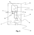
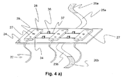
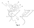
- the antenna arrangement comprises at least two individual antennas, wherein the individual antennas are interconnected by decoupling elements, wherein only the Decoupling elements are fixedly fixed to a carrier body, and the individual antennas are each combined in separate modules, which can be positioned on the carrier body, fixed, and non-destructively removed therefrom.
- the geometry suitable for the object to be imaged can be assembled in a modular manner.
- the carrier body defines the geometry of the antenna array.
- the carrier body is made of MR-compatible, stable material (eg glass fiber reinforced epoxy resin).
- the carrier has a planar geometry.
- the geometry of the carrier body is not limited to this, but may instead have any geometry adapted to the geometry of the object to be imaged.
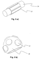
- FIG. 5 a) & b) Further possible geometries for support bodies are shown.
- FIG. 5 a) FIG. 12 illustrates a cylindrical support body as would be used, for example, for an antenna configuration such as would be used to generate whole-body MRI images or MRI images of extremities.
- Fig. 5b represents an approximately spherical support body a cutout as it would be used to generate head MRI images.
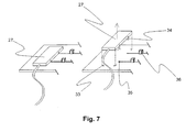
- decoupling elements on the carrier body, which serve to minimize the coupling between the individual antenna modules.
- said decoupling elements consist of contact sleeves, short traces and capacitances.
- Fig. 7 shown in more detail.
- the individual antenna module there are electrical contact pins, which are introduced into the corresponding contact sleeves on the carrier body when the individual antenna module is fastened to the carrier body. This creates an electrical connection between the individual antenna module and the conductor tracks on the carrier body.
- the individual antenna modules are electrically connected to each other in an advantageous manner. 'Advantageously' means that the coupling of the adjacent individual antenna modules is minimized in this way.
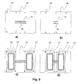
- Fig. 8 is the use of different carrier body and the idea of belonging to the carrier body decoupling again shown somewhat more schematically.
- FIG. 8 a) and Fig. 8 b) put two different Suspringper there.
- the carrier body shown in FIG Fig. 8b) In this case, the distance between the individual antenna modules is smaller than that of the carrier body shown in FIG Fig. 8 a) , The coupling of two antennae lying closer together is greater, which is why the decoupling capacitances which are on the carrier body in Fig. 8b) have a higher capacitance value than the decoupling capacitances on carrier bodies in FIG Fig. 8 a) .
- Fig. 8 c) and d) now put out the respective carrier body Fig. 8 a) and b) with mounted individual antenna modules.
- Fig. 9 a) and b) represent a further possible embodiment of the invention.
- Fig. 9 a) and Fig. 9 b) put two different Collinsköper there.
- the carrier body shown in FIG Fig. 9b) In this case, the distance between the individual antenna modules is smaller than that of the carrier body shown in FIG Fig. 9 a) ,
- the decoupling elements on the carrier bodies now only consist of a closed strip conductor in the form of a butterfly and do not have to be electrically contacted with the individual antenna modules.
- the advantage of this embodiment of the decoupling elements is the fact that no galvanic contact between individual antenna module and decoupling element is necessary.
- the idea of using a conductor loop in the form of a butterfly as a decoupling element is not new, and will be described in detail in detail DE102 44 172 A1 described. Again, the coupling of two antennas closer together is larger. To compensate for the coupling of the two individual antennas, for this reason, the butterfly antenna in Fig. 9d) overlap the single antenna module slightly more than the butterfly antenna in Fig. 9c) ,
- Fig. 10 a) and b) represent a further possible embodiment of the invention.
- the decoupling element is designed as a transformer.
- Fig. 10 a) represents the carrier body with the transformer mounted thereon.
- Fig. 10b) two attached to the carrier body antenna modules are shown, which are contacted with the terminals of the transformer and decoupled therewith.
- a coding element is additionally present on the carrier body for each individual antenna module.
- this coding element consists of a resistor.
- the size of the resistor is different depending on the position on the carrier body and depending on the carrier body geometry. That is to say the resistance value encodes carrier body geometry and individual antenna position on the carrier body.
- one or more capacitive elements of the individual antenna modules are realized as capacitance diodes.
- the voltage values entered in the list have been determined previously and once so that changes in the adaptation of the individual resonant circuits resulting from the different arrangement of the individual antenna modules are corrected.
- the task was the MRI examination of abdomen of mice.
- the cylinder can now be selected, in which the mouse to be examined just barely fits. On this carrier body then the 6 antenna modules are attached. This gives you the desired 6x phased array antenna in the optimal size for the desired examination.
Landscapes
- Physics & Mathematics (AREA)
- Condensed Matter Physics & Semiconductors (AREA)
- General Physics & Mathematics (AREA)
- Magnetic Resonance Imaging Apparatus (AREA)
Claims (9)
- Agencement d'antenne destiné à être utilisé dans un appareil à résonance magnétique, qui est réalisé sous la forme d'un réseau à commande de phase et comprend un corps porteur (24) dans un matériau stable et au moins deux antennes individuelles (8, 11 ; 11a, 11b, 11c), lesquelles présentent chaque fois au moins une boucle conductrice (14), un réseau d'accord (15) et un réseau d'adaptation (16), le réseau d'accord (15) contenant au moins une capacité d'accord (18) et le réseau d'adaptation (16) au moins une capacité d'adaptation (19), et les antennes individuelles (8, 11 ; 11a, 11b, 11c) étant réunies chaque fois dans des modules (27) séparés qui sont positionnés et fixés sur le corps porteur (24) et peuvent être démontés de celui-ci de manière non destructive,
caractérisé en ce
que les antennes individuelles (8, 11 ; 11a, 11b, 11c) sont reliées entre elles par des éléments de découplage (13a, 13b, 13c) pour découpler électromagnétiquement les antennes individuelles (8, 11 ; 11a, 11b, 11c) les unes des autres,
et que les éléments de découplage (13a, 13b, 13c) sont fixés sur le corps porteur (24) et ne peuvent pas être démontés de celui-ci de manière non destructive. - Agencement d'antenne selon la revendication 1, caractérisé en ce que les éléments de découplage (13a, 13b, 13c) prévus sur le corps porteur (24) sont réalisés sous la forme de pistes conductrices (41) présentant une géométrie de type papillon.
- Agencement d'antenne selon la revendication 1, caractérisé en ce que les éléments de découplage (13a, 13b, 13c) prévus sur le corps porteur (24) sont réalisés sous la forme de capacités (36).
- Agencement d'antenne selon la revendication 1, caractérisé en ce que les éléments de découplage (13a, 13b, 13c) prévus sur le corps porteur (24) sont réalisés sous la forme de bobines de découplage inductif.
- Agencement d'antenne selon la revendication 1, caractérisé en ce que les éléments de découplage (13a, 13b, 13c) prévus sur le corps porteur (24) sont réalisés sous la forme de transformateurs (42).
- Agencement d'antenne selon une des revendications précédentes, caractérisé en ce que l'agencement présente un réseau de désaccord (17) qui contient au moins une diode (20).
- Agencement d'antenne selon une des revendications précédentes, caractérisé en ce que le corps porteur (24) est également équipé d'un élément de codage (38, 39) qui code la géométrie du corps porteur (24) et la position des antennes individuelles sur le corps porteur (24), et à l'aide duquel l'alimentation en tension de diodes de capacité dans les antennes individuelles (8, 11 ; 11a, 11b, 11c) peut être réglée.
- Ensemble de corps porteurs (24) de géométrie différente pour l'agencement modulaire de modules d'antenne identiques en vue de construire un agencement d'antenne selon une des revendications précédentes, caractérisé en ce que différents corps porteurs (24) équipés d'éléments de découplage (13a, 13b, 13c) fixes sont prévus, les antennes individuelles pouvant être fixées d'une manière modulaire sur les différents corps porteurs (24) et les éléments de découplage (13a, 13b, 13c) fixés sur les corps porteurs (24) étant choisis de façon que le découplage des antennes individuelles (8, 11 ; 11a, 11b, 11c) entre elles soit maximum.
- Ensemble selon la revendication 8, caractérisé en ce que les corps porteurs (24) sont réalisés sous la forme de cylindres de tailles différentes.
Applications Claiming Priority (1)
| Application Number | Priority Date | Filing Date | Title |
|---|---|---|---|
| DE102010038722A DE102010038722B4 (de) | 2010-07-30 | 2010-07-30 | Modulare MRI Phased Array Antenne |
Publications (2)
| Publication Number | Publication Date |
|---|---|
| EP2413155A1 EP2413155A1 (fr) | 2012-02-01 |
| EP2413155B1 true EP2413155B1 (fr) | 2013-03-13 |
Family
ID=44785189
Family Applications (1)
| Application Number | Title | Priority Date | Filing Date |
|---|---|---|---|
| EP11175518A Active EP2413155B1 (fr) | 2010-07-30 | 2011-07-27 | Antenne à réseau phasé modulaire pour IRM |
Country Status (4)
| Country | Link |
|---|---|
| US (1) | US8692553B2 (fr) |
| EP (1) | EP2413155B1 (fr) |
| JP (1) | JP5611902B2 (fr) |
| DE (1) | DE102010038722B4 (fr) |
Families Citing this family (6)
| Publication number | Priority date | Publication date | Assignee | Title |
|---|---|---|---|---|
| DE112010001412B4 (de) * | 2009-03-31 | 2021-03-25 | The University Of Queensland | Spulenanordnung und Verfahren zur Bestimmung einer Spulenanordnung zur Verwendung in einem bildgebenden Magnetresonanzsystem |
| US8970217B1 (en) | 2010-04-14 | 2015-03-03 | Hypres, Inc. | System and method for noise reduction in magnetic resonance imaging |
| DE102012213995B3 (de) * | 2012-08-07 | 2014-06-12 | Siemens Aktiengesellschaft | System zur elektromagnetischen Anregung bei einer Magnetresonanz-Tomographie sowie Magnetresonanz-Tomograph |
| DE102017213026A1 (de) * | 2017-07-28 | 2019-01-31 | Siemens Healthcare Gmbh | Gradientenspule zur Erzeugung eines Magnetfeldgradienten und eines Magnetfeldes höherer Ordnung |
| CN109856683B (zh) * | 2019-01-07 | 2020-06-16 | 吉林大学 | 拖曳式相控阵电磁探测装置及方法 |
| EP4435456A1 (fr) * | 2023-03-24 | 2024-09-25 | Koninklijke Philips N.V. | Système de bobine radiofréquence pour un appareil d'imagerie par résonance magnétique |
Family Cites Families (31)
| Publication number | Priority date | Publication date | Assignee | Title |
|---|---|---|---|---|
| JPH01126532A (ja) | 1987-11-10 | 1989-05-18 | Takeda Chem Ind Ltd | 局所測定用多核nmrプローブ |
| US4825162A (en) | 1987-12-07 | 1989-04-25 | General Electric Company | Nuclear magnetic resonance (NMR) imaging with multiple surface coils |
| DE3820168A1 (de) | 1988-06-14 | 1989-12-21 | Philips Patentverwaltung | Kernspinuntersuchungsgeraet mit einer schaltung zum entkoppeln der beiden spulensysteme einer quadraturspulenanordnung |
| DE4035844A1 (de) | 1990-11-10 | 1992-05-14 | Philips Patentverwaltung | Quadraturspulenanordnung |
| JP2641808B2 (ja) | 1991-01-31 | 1997-08-20 | 株式会社島津製作所 | Mri用アンテナコイル |
| DE4113120A1 (de) | 1991-04-22 | 1992-11-05 | Siemens Ag | Kernspintomograph |
| JP3167038B2 (ja) | 1991-07-18 | 2001-05-14 | 株式会社日立メディコ | 磁気共鳴イメージング装置 |
| US5329233A (en) * | 1992-12-10 | 1994-07-12 | General Electric Company | Cylindrical local coil for nuclear magnetic resonance imaging |
| US5594337A (en) * | 1993-05-07 | 1997-01-14 | Medical Advances, Inc. | Local coil for magnetic resonance angiography |
| US5351688A (en) * | 1993-08-16 | 1994-10-04 | Univ. Of Ne Board Of Regents | NMR quadrature detection solenoidal coils |
| US5578925A (en) * | 1995-08-18 | 1996-11-26 | Picker International, Inc. | Vertical field quadrature phased array coil system |
| US5905378A (en) | 1997-02-13 | 1999-05-18 | General Electric Company | Flexible lightweight attached phased-array (FLAP) receive coils |
| JP4552291B2 (ja) * | 2000-08-23 | 2010-09-29 | ソニー株式会社 | 情報処理装置および方法、並びに記録媒体 |
| US6591128B1 (en) * | 2000-11-09 | 2003-07-08 | Koninklijke Philips Electronics, N.V. | MRI RF coil systems having detachable, relocatable, and or interchangeable sections and MRI imaging systems and methods employing the same |
| US6650926B1 (en) | 2001-03-30 | 2003-11-18 | Usa Instruments, Inc. | Flexible multi-section MRI radio frequency array coil |
| DE60239412D1 (de) * | 2001-09-14 | 2011-04-21 | Koninkl Philips Electronics Nv | Spulenmodul für magnetische resonanzuntersuchungen |
| US6992486B2 (en) * | 2002-05-16 | 2006-01-31 | Advanced Imaging Research, Inc. | Radio frequency coil for resonance imaging analysis of pediatric patients |
| WO2003098234A2 (fr) * | 2002-05-17 | 2003-11-27 | Mr Instruments, Inc. | Cavite resonnante pour systemes de resonance magnetique |
| DE10226511A1 (de) | 2002-06-14 | 2003-12-24 | Philips Intellectual Property | MR-Anordnung mit Hochfrequenzspulenarrays |
| JP2004033380A (ja) | 2002-07-02 | 2004-02-05 | Ge Medical Systems Global Technology Co Llc | Rfコイルおよび磁気共鳴撮像装置 |
| DE10244172A1 (de) | 2002-09-23 | 2004-03-11 | Siemens Ag | Antennenanordnung für ein Magnetresonanzgerät |
| US20050073309A1 (en) * | 2003-10-01 | 2005-04-07 | Williams Neil R. | Magnetic resonance coil modules |
| WO2005078468A2 (fr) * | 2004-01-20 | 2005-08-25 | The University Of Houston System | Boucle supraconductrice, bobines d'irm en selle de cheval et en cage a oiseaux |
| DE102004046188B4 (de) | 2004-09-23 | 2008-01-10 | Siemens Ag | Antennenanordnung zum Empfang eines Magnetresonanzsignals |
| WO2007046014A2 (fr) | 2005-10-19 | 2007-04-26 | Koninklijke Philips Electronics, N.V. | Reseaux de bobines radiofrequence compacts et flexibles |
| US7659719B2 (en) * | 2005-11-25 | 2010-02-09 | Mr Instruments, Inc. | Cavity resonator for magnetic resonance systems |
| US7498813B2 (en) * | 2006-05-04 | 2009-03-03 | General Electric Company | Multi-channel low loss MRI coil |
| EP2033006A2 (fr) * | 2006-06-09 | 2009-03-11 | Koninklijke Philips Electronics N.V. | Système intégré de bobines mri rf plus des montages en espacement avec des utilisations en confinement biologique |
| JP4866760B2 (ja) | 2007-03-06 | 2012-02-01 | 株式会社日立メディコ | 磁気共鳴イメージング装置 |
| US7728592B2 (en) * | 2008-09-17 | 2010-06-01 | Time Medical Holdings Company Limited | Integrated superconductor MRI imaging system |
| US7772842B2 (en) * | 2008-09-17 | 2010-08-10 | Time Medical Holdings Company Limited | Dedicated superconductor MRI imaging system |
-
2010
- 2010-07-30 DE DE102010038722A patent/DE102010038722B4/de not_active Expired - Fee Related
-
2011
- 2011-07-27 EP EP11175518A patent/EP2413155B1/fr active Active
- 2011-07-27 US US13/137,184 patent/US8692553B2/en active Active
- 2011-07-29 JP JP2011166641A patent/JP5611902B2/ja active Active
Also Published As
| Publication number | Publication date |
|---|---|
| DE102010038722A1 (de) | 2012-02-02 |
| JP2012030076A (ja) | 2012-02-16 |
| EP2413155A1 (fr) | 2012-02-01 |
| DE102010038722B4 (de) | 2012-10-31 |
| JP5611902B2 (ja) | 2014-10-22 |
| US20120025832A1 (en) | 2012-02-02 |
| US8692553B2 (en) | 2014-04-08 |
Similar Documents
| Publication | Publication Date | Title |
|---|---|---|
| EP0352824B1 (fr) | Système localisé de bobines pour examen par RMN | |
| DE102012207722B3 (de) | MR- Antenne mit Kompensation für variablen Abstand zum Schirm | |
| DE4232884C2 (de) | Antennenanordnung für ein Kernspinresonanzgerät | |
| EP2413155B1 (fr) | Antenne à réseau phasé modulaire pour IRM | |
| Hong et al. | New design concept of monopole antenna array for UHF 7T MRI | |
| DE102007047020A1 (de) | Anordnung zur Übertragung von Magnetresonanzsignalen | |
| DE102013213377B3 (de) | Erweiterte Verstimmung bei Lokalspulen | |
| DE102012200600A1 (de) | MRT- Lokalspulenpositions-Erkennung in einem MRT-System | |
| DE69313914T2 (de) | Dynamische Verstimmung einer Feldspule der magnetischen Kernresonanz | |
| DE102010027295B4 (de) | Trommel-Mantelwellensperre | |
| DE102010041202A1 (de) | Magnetresonanzgerät, Reflektor-Array und Hochfrequenzschirmsystem für ein Magnetresonanzgerät | |
| DE4038107C2 (de) | Resonator für einen Kernspintomographen | |
| DE102013214307A1 (de) | Lokale Sendespulen / Sendespulenarray in der Wirbelsäulenbildgebung in einem MRI | |
| DE112016004343T5 (de) | Radiofrequenz-Antennenanordnung für Magnetresonanzbild-Geführte Therapie | |
| DE102021214562B3 (de) | Magnetresonanz-Lokalspule für perkutane MRT-gestützte Nadelintervention | |
| WO2007101741A1 (fr) | Circulateur et appareil à résonnance magnétique | |
| DE102014202716B4 (de) | Verbesserung des lokalen SAR-Verhaltens von MRT-Sendespulen durch Verwendung orthogonaler Schleifenantennen | |
| DE102011086285B4 (de) | Lokalspule | |
| EP3134745B1 (fr) | Dispositif et procédé de raccordement électrique de modules électroniques au moyen de ligne symétrique blindé | |
| DE102012213995B3 (de) | System zur elektromagnetischen Anregung bei einer Magnetresonanz-Tomographie sowie Magnetresonanz-Tomograph | |
| Zhang et al. | Design of a four‐coil surface array for in vivo magnetic resonance microscopy at 600 MHz | |
| DE102011075452B4 (de) | MRT-Lokal-Spulenanordnung | |
| DE102022205796B4 (de) | Mehrkanal-Hochfrequenzarray zum Verfolgen eines medizinischen Instruments | |
| Kumar et al. | Whole-brain imaging with receive-only multichannel top-hat dipole antenna RF coil at 7 T MRI | |
| DE4111508A1 (de) | Vorrichtung zum anregen und/oder messen magnetischer resonanz |
Legal Events
| Date | Code | Title | Description |
|---|---|---|---|
| AK | Designated contracting states |
Kind code of ref document: A1 Designated state(s): AL AT BE BG CH CY CZ DE DK EE ES FI FR GB GR HR HU IE IS IT LI LT LU LV MC MK MT NL NO PL PT RO RS SE SI SK SM TR |
|
| AX | Request for extension of the european patent |
Extension state: BA ME |
|
| PUAI | Public reference made under article 153(3) epc to a published international application that has entered the european phase |
Free format text: ORIGINAL CODE: 0009012 |
|
| 17P | Request for examination filed |
Effective date: 20120720 |
|
| GRAP | Despatch of communication of intention to grant a patent |
Free format text: ORIGINAL CODE: EPIDOSNIGR1 |
|
| RIC1 | Information provided on ipc code assigned before grant |
Ipc: G01R 33/34 20060101ALI20120917BHEP Ipc: G01R 33/3415 20060101AFI20120917BHEP Ipc: G01R 33/36 20060101ALI20120917BHEP |
|
| GRAS | Grant fee paid |
Free format text: ORIGINAL CODE: EPIDOSNIGR3 |
|
| GRAA | (expected) grant |
Free format text: ORIGINAL CODE: 0009210 |
|
| AK | Designated contracting states |
Kind code of ref document: B1 Designated state(s): AL AT BE BG CH CY CZ DE DK EE ES FI FR GB GR HR HU IE IS IT LI LT LU LV MC MK MT NL NO PL PT RO RS SE SI SK SM TR |
|
| REG | Reference to a national code |
Ref country code: GB Ref legal event code: FG4D Free format text: NOT ENGLISH |
|
| REG | Reference to a national code |
Ref country code: AT Ref legal event code: REF Ref document number: 601111 Country of ref document: AT Kind code of ref document: T Effective date: 20130315 Ref country code: CH Ref legal event code: EP |
|
| REG | Reference to a national code |
Ref country code: IE Ref legal event code: FG4D Free format text: LANGUAGE OF EP DOCUMENT: GERMAN |
|
| REG | Reference to a national code |
Ref country code: DE Ref legal event code: R096 Ref document number: 502011000471 Country of ref document: DE Effective date: 20130508 |
|
| PG25 | Lapsed in a contracting state [announced via postgrant information from national office to epo] |
Ref country code: LT Free format text: LAPSE BECAUSE OF FAILURE TO SUBMIT A TRANSLATION OF THE DESCRIPTION OR TO PAY THE FEE WITHIN THE PRESCRIBED TIME-LIMIT Effective date: 20130313 Ref country code: SE Free format text: LAPSE BECAUSE OF FAILURE TO SUBMIT A TRANSLATION OF THE DESCRIPTION OR TO PAY THE FEE WITHIN THE PRESCRIBED TIME-LIMIT Effective date: 20130313 Ref country code: BG Free format text: LAPSE BECAUSE OF FAILURE TO SUBMIT A TRANSLATION OF THE DESCRIPTION OR TO PAY THE FEE WITHIN THE PRESCRIBED TIME-LIMIT Effective date: 20130613 Ref country code: NO Free format text: LAPSE BECAUSE OF FAILURE TO SUBMIT A TRANSLATION OF THE DESCRIPTION OR TO PAY THE FEE WITHIN THE PRESCRIBED TIME-LIMIT Effective date: 20130613 Ref country code: ES Free format text: LAPSE BECAUSE OF FAILURE TO SUBMIT A TRANSLATION OF THE DESCRIPTION OR TO PAY THE FEE WITHIN THE PRESCRIBED TIME-LIMIT Effective date: 20130624 |
|
| REG | Reference to a national code |
Ref country code: NL Ref legal event code: VDEP Effective date: 20130313 |
|
| REG | Reference to a national code |
Ref country code: LT Ref legal event code: MG4D |
|
| PG25 | Lapsed in a contracting state [announced via postgrant information from national office to epo] |
Ref country code: LV Free format text: LAPSE BECAUSE OF FAILURE TO SUBMIT A TRANSLATION OF THE DESCRIPTION OR TO PAY THE FEE WITHIN THE PRESCRIBED TIME-LIMIT Effective date: 20130313 Ref country code: FI Free format text: LAPSE BECAUSE OF FAILURE TO SUBMIT A TRANSLATION OF THE DESCRIPTION OR TO PAY THE FEE WITHIN THE PRESCRIBED TIME-LIMIT Effective date: 20130313 Ref country code: SI Free format text: LAPSE BECAUSE OF FAILURE TO SUBMIT A TRANSLATION OF THE DESCRIPTION OR TO PAY THE FEE WITHIN THE PRESCRIBED TIME-LIMIT Effective date: 20130313 Ref country code: GR Free format text: LAPSE BECAUSE OF FAILURE TO SUBMIT A TRANSLATION OF THE DESCRIPTION OR TO PAY THE FEE WITHIN THE PRESCRIBED TIME-LIMIT Effective date: 20130614 |
|
| PG25 | Lapsed in a contracting state [announced via postgrant information from national office to epo] |
Ref country code: RS Free format text: LAPSE BECAUSE OF FAILURE TO SUBMIT A TRANSLATION OF THE DESCRIPTION OR TO PAY THE FEE WITHIN THE PRESCRIBED TIME-LIMIT Effective date: 20130313 Ref country code: HR Free format text: LAPSE BECAUSE OF FAILURE TO SUBMIT A TRANSLATION OF THE DESCRIPTION OR TO PAY THE FEE WITHIN THE PRESCRIBED TIME-LIMIT Effective date: 20130313 |
|
| PG25 | Lapsed in a contracting state [announced via postgrant information from national office to epo] |
Ref country code: NL Free format text: LAPSE BECAUSE OF FAILURE TO SUBMIT A TRANSLATION OF THE DESCRIPTION OR TO PAY THE FEE WITHIN THE PRESCRIBED TIME-LIMIT Effective date: 20130313 Ref country code: IS Free format text: LAPSE BECAUSE OF FAILURE TO SUBMIT A TRANSLATION OF THE DESCRIPTION OR TO PAY THE FEE WITHIN THE PRESCRIBED TIME-LIMIT Effective date: 20130713 Ref country code: EE Free format text: LAPSE BECAUSE OF FAILURE TO SUBMIT A TRANSLATION OF THE DESCRIPTION OR TO PAY THE FEE WITHIN THE PRESCRIBED TIME-LIMIT Effective date: 20130313 Ref country code: RO Free format text: LAPSE BECAUSE OF FAILURE TO SUBMIT A TRANSLATION OF THE DESCRIPTION OR TO PAY THE FEE WITHIN THE PRESCRIBED TIME-LIMIT Effective date: 20130313 Ref country code: PT Free format text: LAPSE BECAUSE OF FAILURE TO SUBMIT A TRANSLATION OF THE DESCRIPTION OR TO PAY THE FEE WITHIN THE PRESCRIBED TIME-LIMIT Effective date: 20130715 Ref country code: SK Free format text: LAPSE BECAUSE OF FAILURE TO SUBMIT A TRANSLATION OF THE DESCRIPTION OR TO PAY THE FEE WITHIN THE PRESCRIBED TIME-LIMIT Effective date: 20130313 Ref country code: CZ Free format text: LAPSE BECAUSE OF FAILURE TO SUBMIT A TRANSLATION OF THE DESCRIPTION OR TO PAY THE FEE WITHIN THE PRESCRIBED TIME-LIMIT Effective date: 20130313 |
|
| PG25 | Lapsed in a contracting state [announced via postgrant information from national office to epo] |
Ref country code: PL Free format text: LAPSE BECAUSE OF FAILURE TO SUBMIT A TRANSLATION OF THE DESCRIPTION OR TO PAY THE FEE WITHIN THE PRESCRIBED TIME-LIMIT Effective date: 20130313 |
|
| PLBE | No opposition filed within time limit |
Free format text: ORIGINAL CODE: 0009261 |
|
| STAA | Information on the status of an ep patent application or granted ep patent |
Free format text: STATUS: NO OPPOSITION FILED WITHIN TIME LIMIT |
|
| BERE | Be: lapsed |
Owner name: BRUKER BIOSPIN A.G. Effective date: 20130731 |
|
| PG25 | Lapsed in a contracting state [announced via postgrant information from national office to epo] |
Ref country code: DK Free format text: LAPSE BECAUSE OF FAILURE TO SUBMIT A TRANSLATION OF THE DESCRIPTION OR TO PAY THE FEE WITHIN THE PRESCRIBED TIME-LIMIT Effective date: 20130313 |
|
| 26N | No opposition filed |
Effective date: 20131216 |
|
| PG25 | Lapsed in a contracting state [announced via postgrant information from national office to epo] |
Ref country code: MC Free format text: LAPSE BECAUSE OF FAILURE TO SUBMIT A TRANSLATION OF THE DESCRIPTION OR TO PAY THE FEE WITHIN THE PRESCRIBED TIME-LIMIT Effective date: 20130313 Ref country code: IT Free format text: LAPSE BECAUSE OF FAILURE TO SUBMIT A TRANSLATION OF THE DESCRIPTION OR TO PAY THE FEE WITHIN THE PRESCRIBED TIME-LIMIT Effective date: 20130313 |
|
| REG | Reference to a national code |
Ref country code: DE Ref legal event code: R097 Ref document number: 502011000471 Country of ref document: DE Effective date: 20131216 |
|
| REG | Reference to a national code |
Ref country code: IE Ref legal event code: MM4A |
|
| PG25 | Lapsed in a contracting state [announced via postgrant information from national office to epo] |
Ref country code: BE Free format text: LAPSE BECAUSE OF NON-PAYMENT OF DUE FEES Effective date: 20130731 |
|
| PG25 | Lapsed in a contracting state [announced via postgrant information from national office to epo] |
Ref country code: IE Free format text: LAPSE BECAUSE OF NON-PAYMENT OF DUE FEES Effective date: 20130727 |
|
| PG25 | Lapsed in a contracting state [announced via postgrant information from national office to epo] |
Ref country code: SM Free format text: LAPSE BECAUSE OF FAILURE TO SUBMIT A TRANSLATION OF THE DESCRIPTION OR TO PAY THE FEE WITHIN THE PRESCRIBED TIME-LIMIT Effective date: 20130313 |
|
| PG25 | Lapsed in a contracting state [announced via postgrant information from national office to epo] |
Ref country code: MT Free format text: LAPSE BECAUSE OF FAILURE TO SUBMIT A TRANSLATION OF THE DESCRIPTION OR TO PAY THE FEE WITHIN THE PRESCRIBED TIME-LIMIT Effective date: 20130313 Ref country code: TR Free format text: LAPSE BECAUSE OF FAILURE TO SUBMIT A TRANSLATION OF THE DESCRIPTION OR TO PAY THE FEE WITHIN THE PRESCRIBED TIME-LIMIT Effective date: 20130313 Ref country code: CY Free format text: LAPSE BECAUSE OF FAILURE TO SUBMIT A TRANSLATION OF THE DESCRIPTION OR TO PAY THE FEE WITHIN THE PRESCRIBED TIME-LIMIT Effective date: 20130313 |
|
| PG25 | Lapsed in a contracting state [announced via postgrant information from national office to epo] |
Ref country code: MK Free format text: LAPSE BECAUSE OF FAILURE TO SUBMIT A TRANSLATION OF THE DESCRIPTION OR TO PAY THE FEE WITHIN THE PRESCRIBED TIME-LIMIT Effective date: 20130313 Ref country code: HU Free format text: LAPSE BECAUSE OF FAILURE TO SUBMIT A TRANSLATION OF THE DESCRIPTION OR TO PAY THE FEE WITHIN THE PRESCRIBED TIME-LIMIT; INVALID AB INITIO Effective date: 20110727 Ref country code: LU Free format text: LAPSE BECAUSE OF NON-PAYMENT OF DUE FEES Effective date: 20130727 |
|
| REG | Reference to a national code |
Ref country code: FR Ref legal event code: PLFP Year of fee payment: 6 |
|
| REG | Reference to a national code |
Ref country code: FR Ref legal event code: PLFP Year of fee payment: 7 |
|
| REG | Reference to a national code |
Ref country code: AT Ref legal event code: MM01 Ref document number: 601111 Country of ref document: AT Kind code of ref document: T Effective date: 20160727 |
|
| PG25 | Lapsed in a contracting state [announced via postgrant information from national office to epo] |
Ref country code: AT Free format text: LAPSE BECAUSE OF NON-PAYMENT OF DUE FEES Effective date: 20160727 |
|
| REG | Reference to a national code |
Ref country code: FR Ref legal event code: PLFP Year of fee payment: 8 |
|
| PG25 | Lapsed in a contracting state [announced via postgrant information from national office to epo] |
Ref country code: AL Free format text: LAPSE BECAUSE OF FAILURE TO SUBMIT A TRANSLATION OF THE DESCRIPTION OR TO PAY THE FEE WITHIN THE PRESCRIBED TIME-LIMIT Effective date: 20130313 |
|
| REG | Reference to a national code |
Ref country code: DE Ref legal event code: R082 Ref document number: 502011000471 Country of ref document: DE Representative=s name: KOHLER SCHMID MOEBUS PATENTANWAELTE PARTNERSCH, DE Ref country code: DE Ref legal event code: R081 Ref document number: 502011000471 Country of ref document: DE Owner name: BRUKER SWITZERLAND AG, CH Free format text: FORMER OWNER: BRUKER BIOSPIN AG, FAELLANDEN, CH |
|
| REG | Reference to a national code |
Ref country code: CH Ref legal event code: PFA Owner name: BRUKER SWITZERLAND AG, CH Free format text: FORMER OWNER: BRUKER BIOSPIN AG, CH |
|
| P01 | Opt-out of the competence of the unified patent court (upc) registered |
Effective date: 20231221 |
|
| PGFP | Annual fee paid to national office [announced via postgrant information from national office to epo] |
Ref country code: DE Payment date: 20250722 Year of fee payment: 15 |
|
| PGFP | Annual fee paid to national office [announced via postgrant information from national office to epo] |
Ref country code: GB Payment date: 20250724 Year of fee payment: 15 |
|
| PGFP | Annual fee paid to national office [announced via postgrant information from national office to epo] |
Ref country code: FR Payment date: 20250723 Year of fee payment: 15 |
|
| PGFP | Annual fee paid to national office [announced via postgrant information from national office to epo] |
Ref country code: CH Payment date: 20250801 Year of fee payment: 15 |