EP2413784B1 - Dispositif de spectroscopie optique pour détection non invasive du glucose dans le sang et procédé d'utilisation associé - Google Patents
Dispositif de spectroscopie optique pour détection non invasive du glucose dans le sang et procédé d'utilisation associé Download PDFInfo
- Publication number
- EP2413784B1 EP2413784B1 EP10759220.6A EP10759220A EP2413784B1 EP 2413784 B1 EP2413784 B1 EP 2413784B1 EP 10759220 A EP10759220 A EP 10759220A EP 2413784 B1 EP2413784 B1 EP 2413784B1
- Authority
- EP
- European Patent Office
- Prior art keywords
- light
- biological sample
- opening
- interior portion
- optical detection
- Prior art date
- Legal status (The legal status is an assumption and is not a legal conclusion. Google has not performed a legal analysis and makes no representation as to the accuracy of the status listed.)
- Active
Links
Images



Classifications
-
- A—HUMAN NECESSITIES
- A61—MEDICAL OR VETERINARY SCIENCE; HYGIENE
- A61B—DIAGNOSIS; SURGERY; IDENTIFICATION
- A61B5/00—Measuring for diagnostic purposes; Identification of persons
- A61B5/145—Measuring characteristics of blood in vivo, e.g. gas concentration or pH-value ; Measuring characteristics of body fluids or tissues, e.g. interstitial fluid or cerebral tissue
- A61B5/1455—Measuring characteristics of blood in vivo, e.g. gas concentration or pH-value ; Measuring characteristics of body fluids or tissues, e.g. interstitial fluid or cerebral tissue using optical sensors, e.g. spectral photometrical oximeters
-
- A—HUMAN NECESSITIES
- A61—MEDICAL OR VETERINARY SCIENCE; HYGIENE
- A61B—DIAGNOSIS; SURGERY; IDENTIFICATION
- A61B5/00—Measuring for diagnostic purposes; Identification of persons
- A61B5/145—Measuring characteristics of blood in vivo, e.g. gas concentration or pH-value ; Measuring characteristics of body fluids or tissues, e.g. interstitial fluid or cerebral tissue
- A61B5/14532—Measuring characteristics of blood in vivo, e.g. gas concentration or pH-value ; Measuring characteristics of body fluids or tissues, e.g. interstitial fluid or cerebral tissue for measuring glucose, e.g. by tissue impedance measurement
-
- G—PHYSICS
- G01—MEASURING; TESTING
- G01J—MEASUREMENT OF INTENSITY, VELOCITY, SPECTRAL CONTENT, POLARISATION, PHASE OR PULSE CHARACTERISTICS OF INFRARED, VISIBLE OR ULTRAVIOLET LIGHT; COLORIMETRY; RADIATION PYROMETRY
- G01J3/00—Spectrometry; Spectrophotometry; Monochromators; Measuring colours
- G01J3/02—Details
-
- G—PHYSICS
- G01—MEASURING; TESTING
- G01J—MEASUREMENT OF INTENSITY, VELOCITY, SPECTRAL CONTENT, POLARISATION, PHASE OR PULSE CHARACTERISTICS OF INFRARED, VISIBLE OR ULTRAVIOLET LIGHT; COLORIMETRY; RADIATION PYROMETRY
- G01J3/00—Spectrometry; Spectrophotometry; Monochromators; Measuring colours
- G01J3/02—Details
- G01J3/0205—Optical elements not provided otherwise, e.g. optical manifolds, diffusers, windows
- G01J3/0216—Optical elements not provided otherwise, e.g. optical manifolds, diffusers, windows using light concentrators or collectors or condensers
-
- G—PHYSICS
- G01—MEASURING; TESTING
- G01J—MEASUREMENT OF INTENSITY, VELOCITY, SPECTRAL CONTENT, POLARISATION, PHASE OR PULSE CHARACTERISTICS OF INFRARED, VISIBLE OR ULTRAVIOLET LIGHT; COLORIMETRY; RADIATION PYROMETRY
- G01J3/00—Spectrometry; Spectrophotometry; Monochromators; Measuring colours
- G01J3/02—Details
- G01J3/10—Arrangements of light sources specially adapted for spectrometry or colorimetry
-
- G—PHYSICS
- G01—MEASURING; TESTING
- G01J—MEASUREMENT OF INTENSITY, VELOCITY, SPECTRAL CONTENT, POLARISATION, PHASE OR PULSE CHARACTERISTICS OF INFRARED, VISIBLE OR ULTRAVIOLET LIGHT; COLORIMETRY; RADIATION PYROMETRY
- G01J3/00—Spectrometry; Spectrophotometry; Monochromators; Measuring colours
- G01J3/12—Generating the spectrum; Monochromators
- G01J3/18—Generating the spectrum; Monochromators using diffraction elements, e.g. grating
-
- G—PHYSICS
- G01—MEASURING; TESTING
- G01J—MEASUREMENT OF INTENSITY, VELOCITY, SPECTRAL CONTENT, POLARISATION, PHASE OR PULSE CHARACTERISTICS OF INFRARED, VISIBLE OR ULTRAVIOLET LIGHT; COLORIMETRY; RADIATION PYROMETRY
- G01J3/00—Spectrometry; Spectrophotometry; Monochromators; Measuring colours
- G01J3/28—Investigating the spectrum
- G01J3/42—Absorption spectrometry; Double beam spectrometry; Flicker spectrometry; Reflection spectrometry
-
- G—PHYSICS
- G01—MEASURING; TESTING
- G01N—INVESTIGATING OR ANALYSING MATERIALS BY DETERMINING THEIR CHEMICAL OR PHYSICAL PROPERTIES
- G01N21/00—Investigating or analysing materials by the use of optical means, i.e. using sub-millimetre waves, infrared, visible or ultraviolet light
- G01N21/17—Systems in which incident light is modified in accordance with the properties of the material investigated
- G01N21/25—Colour; Spectral properties, i.e. comparison of effect of material on the light at two or more different wavelengths or wavelength bands
- G01N21/31—Investigating relative effect of material at wavelengths characteristic of specific elements or molecules, e.g. atomic absorption spectrometry
- G01N21/35—Investigating relative effect of material at wavelengths characteristic of specific elements or molecules, e.g. atomic absorption spectrometry using infrared light
- G01N21/359—Investigating relative effect of material at wavelengths characteristic of specific elements or molecules, e.g. atomic absorption spectrometry using infrared light using near infrared light
-
- G—PHYSICS
- G01—MEASURING; TESTING
- G01J—MEASUREMENT OF INTENSITY, VELOCITY, SPECTRAL CONTENT, POLARISATION, PHASE OR PULSE CHARACTERISTICS OF INFRARED, VISIBLE OR ULTRAVIOLET LIGHT; COLORIMETRY; RADIATION PYROMETRY
- G01J3/00—Spectrometry; Spectrophotometry; Monochromators; Measuring colours
- G01J3/12—Generating the spectrum; Monochromators
- G01J2003/1226—Interference filters
- G01J2003/1239—Interference filters and separate detectors
Definitions
- Diabetes is a chronic disease that, when not controlled, over time leads to serious damage to many of the body's systems, including the nerves, blood vessels, eyes, kidneys and heart.
- NIDDK National Institute of Diabetes and Digestive and Kidney Diseases
- WHO World Health Organization
- a vital element of diabetes management is the self-monitoring of blood glucose (SMBG) concentration by diabetics in the home environment.
- SMBG blood glucose
- DCCT Diabetes Control and Complications Trial
- Non-invasive blood chemicals detection involves collecting and analyzing light spectra data.
- Extracting information about blood characteristics such as glucose concentration from spectral or other data obtained from spectroscopy is a complex problem due to the presence of components (e.g., skin, fat, muscle, bone, interstitial fluid) other than blood in the area that is being sensed. Such other components can influence these signals in such a way as to alter the reading.
- the resulting signal may be much larger in magnitude than the portion of the signal that corresponds to blood, and therefore limits the ability to accurately extract blood characteristics information.
- EP1300712-A2 describes an optical system includes conical reflectors axially aligned back to back with a xenon tube located in the throat formed by their truncated apices, for emitting light in two opposite directions. Each reflector is enclosed by a transparent cover that includes a central lens for evening out axial light-distribution.
- a xenon tube may be located between the apices of two mutually-inverted conical reflectors at right angles to their common axis for emitting light from their external reflective surfaces throughout 360 degrees.
- a single conical or pyramidal reflector may be used with a LED as light source, and the systems may be used for reception of light.
- WO2009/035669-A1 describes embodiments of the invention relate to a light illumination funnel.
- the funnel includes a first opening positioned to receive an incoming light source, a second opening positioned opposite the first opening and with a diameter smaller than the first opening and inner reflective walls, in contact with the first opening and second opening.
- the funnel has a half angle of less than 25 degrees.
- Embodiments also relate to a light collection funnel and an apparatus utilizing both a light illumination funnel and light collection funnel.
- WO2009/045492-A1 describes embodiments of the invention relate to an apparatus including a light source to generate a plurality of light beams with each of the plurality of light beams having a different wavelength range.
- the apparatus also includes a light funnel to direct the plurality of light beams to the target area, an aperture to direct the plurality of light beams emitting from the target area to a lens, the lens configured to collect the light beams emitting from the target area.
- the apparatus includes a detector including a plurality of light-sensing devices each configured to detect a light beam and configured to generate an output signal indicative of an intensity of light detected and a processor for determining the blood characteristic as a function of each generated output signal.
- US 6865408-B1 describes an apparatus and method for non-invasive measurement of glucose in human tissue by quantitative infrared spectroscopy to clinically relevant levels of precision and accuracy.
- the system includes six subsystems optimized to contend with the complexities of the tissue spectrum, high signal-to-noise ratio and photometric accuracy requirements, tissue sampling errors, calibration maintenance problems, and calibration transfer problems.
- the six subsystems include an illumination subsystem, a tissue sampling subsystem, a calibration maintenance subsystem, an FTIR spectrometer subsystem, a data acquisition subsystem, and a computing subsystem.
- EP0781527-A1 describes a pulsoximeter sensor for measuring the degree of oxygen saturation in a patient's blood non-invasively.
- a sensor comdprises: radiation sources, which emit measuring radiation with at least two wavelengths to a portion of the body of a patient; a detector for receiving the measuring radiation having passed through said body portion of a patient and for converting the same to electric form; as well as at least one radiation transfer section, which is located between either the radiation sources or respectively the detectors and the external surface of said body portion of a patient.
- the radiation transfer section includes measuring-radiation transmitting ends, whereof an outer end facing the external body surface has a surface area which is generally larger than the surface area of an inner end facing any given radiation sources or respectively detectors, as well as a measuring-radiation diffusively reflecting surface between these ends.
- Embodiments of the present invention relate to optical components, such as light funnels for illumination and measurement of optical properties of a sample. Although spectroscopic sampling of human or animal body regions are exemplified, the embodiments relate to all types of optical instrumentation, including optical detectors, microscopes, spectrometers, etc.
- Optical spectroscopy can be used to determine the amount of light absorbed by a biological sample such as human finger. By measuring the amount of light absorbed by the finger, it is possible to determine glucose, cholesterol, and hemoglobin levels of a person non-invasively. Fingertip measurements are usually preferred because of the large concentration of capillaries in the fingertip and because of the conversion of arterial blood into venous blood that occurs in the fingertip. However, the techniques of the present invention are not limited to use with a human finger. For example, the use of other samples, such as a human earlobe, may be desirable.
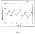
- FIG. 1 depicts a plot 102 of a cyclic detector photocurrent, I D (t) , that corresponds to the light absorption of arterial blood in the capillary due to the heartbeat of the user.
- I D (t) a cyclic detector photocurrent
- the photocurrent will have a maximum or peak 104 reading and minimum or valley 106 reading.
- the peak 104 reading of the plot corresponds to when there is a minimum amount of blood in the capillaries
- the valley 106 reading corresponds to when there is a maximum amount of blood in the capillaries.
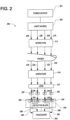
- FIG. 2 is a simplified block diagram that illustrates components of a current optical measurement system, which is generally indicated by numeral 200, which uses the "pulsatile" concept for determining an amount of light absorbed and scattered solely by the blood in a sample (e.g. human finger).
- a power source 201 such as a battery, provides power to a light source 202 that generates a plurality of light beams 204, 206, 208, 210 that are directed toward the top of the finger of a user.
- each of the light beams 204, 206, 208, 210 have the same wavelength range, typically from about 700 nm to about 1600 nm.
- the optical measurement system 200 is described herein as generating four (4) light beams, it is contemplated that the light source 202 can be altered to generate fewer light beams or additional light beams in other embodiments.
- a first aperture 212 ensures that the light beams 204, 206, 208, 210 strike a target area of the sample (e.g. human finger).
- a second aperture 214 ensures that the portion of the light beams that are transmitted through the sample strike a lens 216.
- Light beams 204, 206, 208, 210 are attenuated by the sample and components of the optical measurement system 200, and, thus, attenuated light beams 218, 220, 222, 224 are emitted from the sample.
- the attenuated light beams 218, 220, 222, 224 strike the lens 216, and the lens 216 collects the attenuated light beams 218, 220, 222, 224 so that they impinge more efficiently on a detector block 226.
- the detector block 226 is positioned directly under the lens 216 and comprises a plurality of light-sensing devices (LSD) 228, 230, 232, 234 such as an array of photodiodes.
- LSD light-sensing devices
- each of the light-sensing devices 228, 230, 232, 234 is tuned to detect a specific spectrum (or spectrums) of light.
- each light-sensing device may be associated with a corresponding interference filter (IF), such as filters 236, 238, 240, 242.
- IF interference filter
- An interference filter transmits one or more spectral bands or lines of light, and substantially blocks others.
- Each of the light-sensing devices 228, 230, 232, 234 generates a corresponding photocurrent signal 244, 246, 248, 250 that is proportional to the power of the light received by the particular light sensing device.
- the photocurrent signal generated by the photodiode can be converted to another form of signal, such as an analog voltage signal or a digital signal.
- Processor 243 is coupled to the detector block 226 and is configured to calculate the change of photocurrent signals 244, 246, 248, 250.
- processor 243 executes an algorithm such as shown in the Equation indicated by numeral (5) above, to calculate the change in the light absorption ( ⁇ A) solely caused by the blood in the finger. Thereafter, this quantitative calculation of light absorption of the blood can be used to determine a characteristic of the blood. For example, by comparing the calculated light absorption value to predetermined values corresponding to different glucose levels stored in a memory (not shown), a glucose level of the user can be determined.
- a difficulty associated with the finger based pulsatile detection methodology is low signal-to-noise ("S/N") ratio, because the amplitude of cyclic pattern (i.e., the difference between peak and valley) is typically 1%-2% of the total photocurrent generated by the light power transmitted through the sample (e.g. a person's finger).
- S/N ratio 100:1 in the determination of ⁇ A
- the baseline noise of the device being used to measure the light absorption by the sample should not be larger than 3.0 ⁇ 10 -5 in absorbance (peak to peak), within a 10 Hz bandwidth.
- FIG. 3 depicts the configuration of a conventional, prior art apparatus for measuring the amount of light absorbed by a sample (e.g. human finger).
- a lamp 302 generates near infrared ("NIR") radiation or light beams from 700 nm to 1600 nm.
- the generated NIR light beams enter an entrance aperture 304 and pass through the sample.
- the NIR light beams transmitted through the sample pass through an exit aperture 306 onto a lens 308.
- the lens 308 collimates light beams and projects them onto filter array 310 and then detector array 312.
- the apparatus also includes a wall housing 314 to prevent stray light from reaching the light detectors.
- the optical system shown in FIG. 3 has very low optical power efficiency.
- entrance aperture 304 typically has a diameter of approximately 0.25 (1/4) inches or less.
- Light transmitted through the sample is collected through an exit aperture 306.
- Exit aperture 306 typically has a diameter of approximately 0.25 (1/4) inches or less.
- Most light power emitted from the lamp 302 cannot reach the target area due to a small illumination solid angle.
- the optical configuration shown in FIG. 3 also has a small solid angle for light collection. Light is emitted from the exit aperture 306 into the entire 2 ⁇ solid angle beneath the sample.
- the total light power collected using optical system shown in FIG. 3 is typically about 10% of the light power emitted through the aperture 306.
- the entire light power distribution from 700 nm to 1600 nm is transmitted to every detector in the detector array 312, and each detector typically detects only a relatively narrow wavelength bandwidth, ⁇ 10 nm. As such, up to 98% of light power (or more) is wasted.
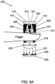
- FIG. 4A depicts an optical measurement system 400 for performing optical detection of a biological sample according to an exemplary, first alternative embodiment.
- the system includes light illumination funnel 412, which may be constructed according to the techniques described below with reference to FIG. 5 .
- a small light source 402 e.g., lamp, is disposed within the interior portion of light illumination funnel 412, and generates a plurality of light beams 404, 406, 408, 410.
- Each of the light beams 404, 406, 408, 410 have the same wavelength range from about 700 nm to about 1600 nm, for example.
- the optical measurement system 400 is described herein as generating four (4) light beams, it is contemplated that the light source can be altered to generate fewer light beams or additional light beams in other embodiments.
- the diameter of the exit opening 416 of the light illumination funnel 412 is larger than or equal to the funnel diameter 414 near the anterior end. Electrodes 413 and 415 of the light source 402 are connected to the lamp control board 401.
- the funnel diameter 414 is approximately 0.125 (1/8) inch and the diameter of the exit opening 416 is approximately 0.25 (1/4) inch.
- the light illumination funnel 412 focuses the light beams 404, 406, 408, 410 into the same general direction toward the top of the sample.
- the light illumination funnel may significantly increase the total light power received by the target area in comparison to the configuration of FIG. 3 , and therefore substantially increase the S/N ratio.
- FIG. 5 depicts a cross sectional view of an exemplary light funnel 512.
- Light funnel 512 could be used as a light illumination funnel e.g., 412 in FIGS. 4A , 4B , or 4C , or light collection funnel, e.g. 434 in FIG. 4C .
- Exemplary light funnel 512 has a substantially cylindrical outer wall 502 with diameter D1, and an interior portion defined by an inner wall 506 that has a substantially frusto-conical shape.
- the interior portion of the funnel has a diameter D2 at the anterior end 504.
- the funnel has an exit opening 508 at the posterior end. Opening 508 (light exit) has a diameter D3 that is larger than D2.
- the separation distance between the two ends is L
- the Half Angle of the frusto-conical shape of the inner surface is ⁇ .
- the Half Angles are less than about 45 degrees. In an exemplary embodiment, the value of Half Angle ⁇ is about 5 to about 25 degrees.
- the light funnel 512 may be formed from plastic, metal, or other suitable material or compound/layers of material, with any desired refractive index(es). According to one aspect, the light funnel 512 is formed from metal and the surface of inner wall 506 is made highly reflective. With the light illumination funnel, the total light illumination power received by the target area may be increased by a factor of 3 to 4 over the light illumination configuration shown in FIG. 3 .
- FIG. 6 depicts an exemplary optical apparatus, which is generally indicated by numeral 600, which includes a light source 606, e.g., lamp, and a light illumination funnel 612.
- a printed circuit board ('PCB") 602 for lamp power control may be positioned near or in contact with the anterior end of the light illumination funnel.
- Light source 606, e.g., lamp is connected to the board 602 via wires that pass through the anterior end of the funnel.
- Light source 606, e.g., lamp may be mounted to the PCB 602.
- the PCB 602 receives electric power through power lines 604 that is connected to a power source, e.g., power source 201, e.g., battery, shown in FIG. 2 .
- the light source 606, e.g., lamp When the electric power is supplied through the power lines 604, the light source 606, e.g., lamp, generates a plurality of light beams e.g., light beams 404, 406, 408, and 410, shown in FIGS. 4A , 4B , and 4C .
- the position of the light source 606, e.g., lamp, inside the funnel can be adjusted as to maximize the illumination power received by the large opening 608 (the light exit).
- light illumination funnel 612 is mounted to PCB 602 via screws, posts or other connecting means.
- the frusto-conical shape of the inner surface of the light illumination funnel 612 serves to concentrate and focus the light beams 404, 406, 408, 410, shown in FIGS. 4A , 4B , and 4C , from the lamp into a generally conical beam toward the finger.
- light beams 404, 406, 408, 410 are attenuated by the sample and components of the optical measurement system 400.
- the attenuated light beams then pass an exit aperture 418, collected by a condenser lens 420, e.g., aspheric lens.
- the beams 421 exiting the condenser lens 420, e.g., aspheric lens, may then pass through filters 426 to detectors 428.
- An advantage of using a condenser lens 420, e.g., aspheric lens, for light collection is its large solid angle for light collection.
- the total light power received by each detector may be increased by a factor 3 to 4 when a condenser lens 420, e.g., aspheric lens, is used for collecting light emitted from the target area in comparison to the light collection configuration shown in FIG. 3 .
- the combination of utilizing a light illumination funnel 412 and an condenser lens 420, e.g., aspheric lens, as light collector may increase the total light power received by each detector by about nine times to about sixteen times in comparison to the optical configuration shown in FIG. 3 .
- the detector block 428 is positioned beneath the condenser lens 420, e.g., aspheric lens, and may include a plurality of light-sensing devices, such as an array of photodiodes. Each of the light-sensing devices detects a specific spectrum of light. In an exemplary embodiment, an interference filter 426 is placed on top of each light-sensing device.
- a processor e.g., processor 243 shown in FIG. 2
- the processor 243 executes an algorithm such as shown in equation (5) to calculate the change in the light absorption (AA) solely caused by the blood in a finger. Thereafter, this quantitative calculation of light absorption of the blood can be used to determine a characteristic of the blood.
- FIG. 4B illustrates a preferred embodiment of optical configuration for performing optical detection of a biological sample and is generally indicated by numeral 460.
- Light source 402 generates a plurality of light beams 404, 406, 408, 410.
- the light source 402 may be incandescent light sources or infrared emitting diodes, for example.
- each of the light beams 404, 406, 408, 410 have the same wavelength range from 700 nm to 1600 nm, for example.
- the optical measurement system 460 is described herein as generating four (4) light beams, it is contemplated that the light source can be altered to generate fewer light beams or additional light beams in other embodiments.
- the diameter of the exit opening 416 of the light illumination funnel 412 is larger than or equal to the diameter of the opening 414 on the top, through which the two electrodes 413 and 415 of the light source 402 is connected to the lamp control board 401.
- the diameter of the entrance opening 414 is approximately 0.125 (1/8) inch and the diameter of the exit opening 416 is approximately 0.25 (1/4) inch.
- the light illumination funnel 412 focuses the light beams 404, 406, 408, 410 in the same general direction toward the top of the finger of a user.
- the light illumination funnel may significantly increase the total light power received by the target area in comparison to the configuration of FIG. 3 , and therefore substantially increase the S/N ratio.
- light beams 404, 406, 408, 410 are attenuated by the sample and components of the optical measurement system.
- the attenuated light NIR beams then pass an exit aperture 418, are collected by a condenser lens 420, e.g., aspheric lens, and projected onto a transmission grating device 422.
- Transmission diffraction grating 422 angularly resolves the various wavelength components of the mixed NIR light beams into a spectrum with wavelength increasing monotonically in the direction depicted by arrow 430.
- the optical spectrum 424 exiting the transmission diffraction grating 422 may then be narrowed down by optional interference filter array 426.
- Light is detected by photodetector array 428 (e.g. photodiodes).
- the detectors in array 428 may be positioned so that detectors tuned to a particular spectrum of light receive light from the transmission diffraction grating 422 within that spectrum.
- the center wavelength of each interference filter in the filter array 426 may be arranged to increase monotonically to coincide with corresponding wavelength component of the spectrum from the transmission diffraction grating 422. It will be apparent that the use of filters, e.g., filter array 426, is optional, and not necessary.
- the approach utilizing transmission diffraction grating will limit the spectrum sent to each detector to wavelength components near the center wavelength of the detector (and/or corresponding filter).
- the amount of light wasted is dramatically reduced, and the light power received by the photodiodes may be increased by a factor of 10 times to 20 times in comparison to the light collection configuration described in reference to FIG. 4A .
- the combination of utilizing a light illumination funnel 412, a condenser lens 420, e.g., aspheric lens, as light collector, and a transmission grating 422 as wavelength separation device may increase the light power received by the photodiodes by about 100 to about 200 times in comparison to the optical configuration shown in FIG. 3 .
- FIG. 4C illustrates an exemplary, second alternative embodiment generally indicated by numeral 462.
- the optical measurement system 462 is described herein as generating four (4) light beams, it is contemplated that the light source can be altered to generate fewer light beams or additional light beams in other embodiments.
- the light beams 404, 406, 408, 410 from the light source 402 exit the light illumination funnel 412 through an exit opening 416.
- the diameter of the exit opening 416 of the light illumination funnel 412 is larger than or equal to the diameter of the opening 414 on the top, through which the two electrodes 413 and 415 of the light source 402 is connected to the lamp control board 401.
- the diameter of the entrance opening 414 is approximately 0.125 (1/8) inch and the diameter of the exit opening 416 is approximately 0.25 (1/4) inch.
- Light illumination funnel 412 illuminates a sample (e.g. a finger).
- Light beams 404, 406, 408, 410 are attenuated by the sample and components of the optical measurement system. Attenuated light beams 436, 438, 444, 446 are emitted from the sample. Attenuated light beams 436, 438, 444, 446 enter light collection funnel 434 through an entrance opening 442 (first opening) and exit the light collection funnel 434 through an exit opening 440 (second opening).
- the diameter of the entrance opening 442 of the light collection funnel 434 is less than or equal to the diameter of the exit opening 440.
- the diameter of the exit opening 440 is approximately 0.625 (5/8) inch and the diameter of the entrance opening 442 is approximately 0.25 (1/4) inch.
- Light collection funnel 434 may project the collected light onto filter array 426.
- Light collection funnel 434 may be constructed according to the techniques described below with reference to FIG. 5 .
- exemplary light collection funnel 434 has a substantially cylindrical outer wall 502 and a central opening defined by an inner wall 506 that is of a frusto-conical shape.
- the light funnel collector 434 may also be formed from plastic, metal, or other suitable material or compound/layers of material with any desired refractive index(es).
- Light collection funnel 434 may be formed from metal and the surface of the frusto-conical shape inner wall may be made highly reflective. It has been observed that the overall collection efficiency of light collection funnel 434 is over 80%, which is eight times that obtained using traditional optical collection structure shown in FIG. 3 .
- the combination of utilizing a light illumination funnel 412 and light collection funnel 434 may increase the light power received by the detectors by about 20 to about 30 times in comparison to the optical configuration in FIG. 3
- Filter array 426 and detector array 428 are positioned beneath the exit opening 440 of the light collection funnel 434 and comprises a plurality of light-sensing devices, e.g. light sensing devices 228, 230, 232, 234 shown in FIG. 2 , such as an array of photodiodes.
- each of the light-sensing devices detects a specific wavelength of light.
- Embodiments of the invention may also include methods of using the apparatus as describe above or a light collection system.
- a light source may contact a target through an illumination funnel, sufficient to generate transmitted, transflected or reflected light.
- the transmitted, transflected or reflected light may enter a light collection system and be directed to one or more detectors, for example.
Landscapes
- Physics & Mathematics (AREA)
- Spectroscopy & Molecular Physics (AREA)
- Health & Medical Sciences (AREA)
- Life Sciences & Earth Sciences (AREA)
- General Physics & Mathematics (AREA)
- General Health & Medical Sciences (AREA)
- Pathology (AREA)
- Molecular Biology (AREA)
- Heart & Thoracic Surgery (AREA)
- Veterinary Medicine (AREA)
- Public Health (AREA)
- Animal Behavior & Ethology (AREA)
- Optics & Photonics (AREA)
- Biophysics (AREA)
- Engineering & Computer Science (AREA)
- Biomedical Technology (AREA)
- Surgery (AREA)
- Medical Informatics (AREA)
- Chemical & Material Sciences (AREA)
- Biochemistry (AREA)
- Emergency Medicine (AREA)
- Analytical Chemistry (AREA)
- Immunology (AREA)
- Investigating Or Analysing Materials By Optical Means (AREA)
- Measurement Of The Respiration, Hearing Ability, Form, And Blood Characteristics Of Living Organisms (AREA)
- Optical Measuring Cells (AREA)
Claims (10)
- Appareil pour la détection optique d'un échantillon biologique, l'appareil comprenant :a) un cône d'éclairage (412) ayant :(i) une première paroi extérieure (502) ayant une extrémité antérieure, une extrémité postérieure, une surface intérieure (506) et une surface extérieure, la surface intérieure définissant une partie intérieure, la partie intérieure ayant une extrémité antérieure et une extrémité postérieure ; et(ii) une source de lumière (402) disposée dans la partie intérieure ;la première paroi extérieure ayant une ouverture (416) dans l'extrémité postérieure, l'ouverture ayant un diamètre d'ouverture ;la partie intérieure ayant une forme sensiblement tronconique ;la partie intérieure ayant un premier diamètre de section transversale au niveau de l'ouverture (416) égal au diamètre d'ouverture et un second diamètre de section transversale (414) près de l'extrémité antérieure qui est inférieur au diamètre d'ouverture (416) ; etla surface intérieure étant photoréfléchissante ;un échantillon biologique pouvant être positionné sous l'ouverture dans la première paroi extérieure de manière à recevoir la lumière provenant de la source de lumière ;le cône d'éclairage présentant un demi-angle de forme tronconique inférieur à 45 degrés, le demi-angle de forme tronconique étant un angle entre l'axe longitudinal de la forme tronconique et une ligne qui s'étend du second diamètre transversal au premier diamètre transversal ;b) un collecteur de lumière configuré pour être positionné sous l'échantillon biologique et recevoir la lumière provenant de l'échantillon biologique, lorsque l'échantillon biologique est présent ;c) une pluralité de filtres de lumière (426) situés sous le collecteur de lumière ; et,d) une pluralité de photo-détecteurs (428) situés sous la pluralité de filtres de lumière (426), chaque filtre de lumière de la pluralité de filtres de lumière (426) étant positionné pour recevoir la lumière provenant de l'échantillon biologique et émettre une lumière filtrée sur un photo-détecteur correspondant de la pluralité de photo-détecteurs (428) et chaque photo-détecteur de la pluralité de photo-détecteurs (428) étant réglé pour détecter la lumière dans le spectre émis par le filtre de lumière correspondant de la pluralité de filtres de lumière.
- Appareil pour la détection optique d'un échantillon biologique selon la revendication 1, la première paroi extérieure (502) comprenant du métal, et la surface intérieure (506) étant polie.
- Appareil pour la détection optique d'un échantillon biologique selon la revendication 1, le demi-angle de la forme tronconique étant supérieur à cinq degrés et inférieur à vingt-cinq degrés.
- Appareil pour la détection optique d'un échantillon biologique selon la revendication 1, le collecteur de lumière étant une lentille de condenseur (420), positionnée sous une ouverture située entre l'échantillon et la lentille de condenseur, pour recevoir la lumière provenant de l'échantillon biologique.
- Appareil pour la détection optique d'un échantillon biologique selon la revendication 4, la lentille de condenseur (420) étant une lentille asphérique.
- Appareil pour la détection optique d'un échantillon biologique selon la revendication 4, comprenant en outre un réseau de diffraction (422) positionné sous la lentille de condenseur (420).
- Procédé pour la détection optique d'un échantillon biologique à l'aide d'un appareil comprenant :a) un cône d'éclairage (412) ayant :(i) une première paroi extérieure (502) ayant une extrémité antérieure, une extrémité postérieure, une surface intérieure (506) et une surface extérieure, la surface intérieure définissant une partie intérieure, la partie intérieure ayant une extrémité antérieure et une extrémité postérieure ; et(ii) une source de lumière (402) disposée dans la partie intérieure ;la première paroi extérieure ayant une ouverture (416) dans l'extrémité postérieure, l'ouverture ayant un diamètre d'ouverture ;la partie intérieure ayant une forme sensiblement tronconique ;la partie intérieure ayant un premier diamètre de section transversale au niveau de l'ouverture (416) égal au diamètre d'ouverture et un second diamètre de section transversale (414) près de l'extrémité antérieure qui est inférieur au diamètre d'ouverture (416) ; etla surface intérieure étant photoréfléchissante ;un échantillon biologique pouvant être positionné sous l'ouverture dans la première paroi extérieure de manière à recevoir la lumière provenant de la source de lumière ;le cône d'éclairage présentant un demi-angle de la forme tronconique inférieur à 45 degrés, le demi-angle de la forme tronconique étant un angle entre l'axe longitudinal de la forme tronconique et une ligne qui s'étend du second diamètre transversal au premier diamètre transversal ;b) un collecteur de lumière configuré pour être positionné sous l'échantillon biologique et recevoir la lumière provenant de l'échantillon biologique, lorsque l'échantillon biologique est présent ;c) une pluralité de filtres de lumière (426) situés sous le collecteur de lumière ; et,d) une pluralité de photo-détecteurs (428) situés sous la pluralité de filtres de lumière (426),chaque filtre de lumière de la pluralité de filtres de lumière (426) étant positionné pour recevoir la lumière provenant de l'échantillon biologique et émettre la lumière filtrée sur un photo-détecteur correspondant de la pluralité de photo-détecteurs (428) et chaque photo-détecteur de la pluralité de photo-détecteurs (428) étant réglé pour détecter la lumière dans le spectre émis par le filtre de lumière correspondant de la pluralité de filtres de lumière, le procédé comprenant :l'utilisation de la source de lumière (402) ;le positionnement d'un échantillon biologique sous l'ouverture dans la première paroi extérieure et au-dessus du collecteur de lumière de sorte que l'échantillon biologique reçoive la lumière provenant de la source de lumière (402) et que le collecteur de lumière reçoive la lumière provenant de l'échantillon biologique ;l'utilisation du collecteur de lumière sous l'échantillon biologique pour collecter la lumière provenant de l'échantillon biologique ;l'utilisation de la pluralité de filtres de lumière (426) situés sous la lentille de condenseur ; etl'utilisation d'une pluralité de photo-détecteurs (428) situés sous la pluralité de filtres de lumière (426), chaque filtre de lumière de la pluralité de filtres de lumière (426) étant positionné pour recevoir la lumière provenant de l'échantillon biologique et émettre une lumière filtrée sur un photo-détecteur correspondant de la pluralité de photo-détecteurs (428) et chaque photo-détecteur de la pluralité de photo-détecteurs (428) étant réglé pour détecter la lumière dans le spectre émis par le filtre de lumière correspondant de la pluralité de filtres de lumière.
- Procédé pour la détection optique d'un échantillon biologique selon la revendication 7, le collecteur de lumière étant une lentille de condenseur (420).
- Procédé pour la détection optique d'un échantillon biologique selon la revendication 8, la lentille de condenseur étant positionnée sous une ouverture et recevant la lumière provenant de l'échantillon.
- Procédé pour la détection optique d'un échantillon biologique selon la revendication 9, la pluralité de photo-détecteurs (428) étant constituée par un réseau de photo-détecteurs (428).
Applications Claiming Priority (2)
| Application Number | Priority Date | Filing Date | Title |
|---|---|---|---|
| US16554709P | 2009-04-01 | 2009-04-01 | |
| PCT/US2010/028255 WO2010114736A1 (fr) | 2009-04-01 | 2010-03-23 | Dispositif de spectroscopie optique pour détection non invasive du glucose dans le sang et procédé d'utilisation associé |
Publications (4)
| Publication Number | Publication Date |
|---|---|
| EP2413784A1 EP2413784A1 (fr) | 2012-02-08 |
| EP2413784A4 EP2413784A4 (fr) | 2014-01-22 |
| EP2413784C0 EP2413784C0 (fr) | 2024-07-17 |
| EP2413784B1 true EP2413784B1 (fr) | 2024-07-17 |
Family
ID=42825408
Family Applications (1)
| Application Number | Title | Priority Date | Filing Date |
|---|---|---|---|
| EP10759220.6A Active EP2413784B1 (fr) | 2009-04-01 | 2010-03-23 | Dispositif de spectroscopie optique pour détection non invasive du glucose dans le sang et procédé d'utilisation associé |
Country Status (9)
| Country | Link |
|---|---|
| US (1) | US8552359B2 (fr) |
| EP (1) | EP2413784B1 (fr) |
| JP (1) | JP2012522579A (fr) |
| CN (1) | CN102438511B (fr) |
| AU (1) | AU2010232841B2 (fr) |
| BR (1) | BRPI1010304B1 (fr) |
| CA (1) | CA2789658C (fr) |
| RU (1) | RU2595488C2 (fr) |
| WO (1) | WO2010114736A1 (fr) |
Families Citing this family (28)
| Publication number | Priority date | Publication date | Assignee | Title |
|---|---|---|---|---|
| BRPI0909825B8 (pt) | 2008-03-25 | 2021-06-22 | Univ Missouri | método e sistemas para detecção não-invasiva de glicose sanguíneo utilizando dados espectrais de um ou mais componentes que não a glicose |
| EP2299900B1 (fr) | 2008-05-22 | 2017-06-07 | St. Louis Medical Devices, Inc. | Procédé et système de détection optique non invasif du glucose sanguin utilisant l'analyse de données spectrales |
| CA2789658C (fr) | 2009-04-01 | 2017-11-07 | The Curators Of The University Of Missouri | Dispositif de spectroscopie optique pour detection non invasive du glucose dans le sang et procede d'utilisation associe |
| WO2014065039A1 (fr) * | 2012-10-26 | 2014-05-01 | ソニー株式会社 | Unité de concentration de lumière, procédé de concentration de lumière et système de détection de lumière |
| CN103078160B (zh) * | 2013-01-15 | 2015-09-23 | 武汉大学 | 一种微波超分辨率聚焦装置 |
| WO2014137357A1 (fr) * | 2013-03-08 | 2014-09-12 | Alethus, Inc. | Détection optique sélective de substances présentes dans des tissus et des milieux troubles et utilisation à des fins d'analyse non invasive |
| JP5864639B2 (ja) * | 2014-02-20 | 2016-02-17 | シャープ株式会社 | 測定装置 |
| WO2016054079A1 (fr) | 2014-09-29 | 2016-04-07 | Zyomed Corp. | Systèmes et procédés pour la détection et la mesure du glucose sanguin du sang et d'autres analytes à l'aide du calcul de collision |
| WO2016050486A1 (fr) | 2014-10-02 | 2016-04-07 | Koninklijke Philips N.V. | Capteur optique de signes vitaux |
| US10267956B2 (en) | 2015-04-14 | 2019-04-23 | California Institute Of Technology | Multi-wavelength optical dielectric metasurfaces |
| US10881336B2 (en) * | 2015-08-21 | 2021-01-05 | California Institute Of Technology | Planar diffractive device with matching diffraction spectrum |
| US10670782B2 (en) | 2016-01-22 | 2020-06-02 | California Institute Of Technology | Dispersionless and dispersion-controlled optical dielectric metasurfaces |
| US9554738B1 (en) | 2016-03-30 | 2017-01-31 | Zyomed Corp. | Spectroscopic tomography systems and methods for noninvasive detection and measurement of analytes using collision computing |
| US10215703B2 (en) * | 2016-11-11 | 2019-02-26 | B&W Tek Llc | Apparatus and method for performing spectroscopic analysis of a subject using a frustum shaped reflective cavity |
| US10488651B2 (en) | 2017-04-10 | 2019-11-26 | California Institute Of Technology | Tunable elastic dielectric metasurface lenses |
| DE112019000207T5 (de) | 2018-01-22 | 2020-08-06 | Spectricity | Optische Erfassung von Reaktionen von Haut und Gewebe mittels Spektroskopie |
| JP2021522510A (ja) | 2018-04-30 | 2021-08-30 | ニューオン インコーポレイテッド | 血液分析のためのシステムおよび方法 |
| KR102680471B1 (ko) | 2018-10-23 | 2024-07-03 | 삼성전자주식회사 | 소형 분광 유닛 및 생체 신호 측정 장치 |
| KR102693439B1 (ko) * | 2018-11-20 | 2024-08-07 | 삼성전자주식회사 | 스펙트럼 측정 장치, 스펙트럼의 광원 온도 변화 보정 방법, 농도 추정 장치 및 방법 |
| CN111317442B (zh) | 2018-12-14 | 2022-12-06 | 天津先阳科技发展有限公司 | 一种组织成分无创检测装置、系统及可穿戴设备 |
| US20220331028A1 (en) | 2019-08-30 | 2022-10-20 | Metralabs Gmbh Neue Technologien Und Systeme | System for Capturing Movement Patterns and/or Vital Signs of a Person |
| KR102834795B1 (ko) * | 2019-09-11 | 2025-07-15 | 삼성전자주식회사 | 렌즈, 렌즈가 적용된 광원 장치 및 분석 물질의 농도 추정 장치 |
| JPWO2022070421A1 (fr) * | 2020-10-02 | 2022-04-07 | ||
| US20220142516A1 (en) * | 2020-11-06 | 2022-05-12 | Nueon Inc. | Method and systems for using surrogate markers to improve nutrition, fitness, and performance |
| CN113288137B (zh) * | 2021-07-06 | 2023-06-27 | 中科搏锐(北京)科技有限公司 | 一种全脑域血氧检测探头 |
| WO2023068954A1 (fr) * | 2021-10-19 | 2023-04-27 | Олег Олегович ТИХОНЕНКО | Procédé de détermination non invasive de la composition du sang |
| CN116518346A (zh) * | 2023-04-07 | 2023-08-01 | 浙江极氪智能科技有限公司 | 氛围灯装置及其调节方法、车辆 |
| CN116898431A (zh) * | 2023-06-25 | 2023-10-20 | 苏州优化医疗科技有限公司 | 一种多波段近红外发光拍摄装置及数据采集方法 |
Family Cites Families (140)
| Publication number | Priority date | Publication date | Assignee | Title |
|---|---|---|---|---|
| US2441343A (en) * | 1944-07-07 | 1948-05-11 | Borg Warner | Photoelectric ring gauge |
| US3621268A (en) * | 1967-12-19 | 1971-11-16 | Int Standard Electric Corp | Reflection type contactless touch switch having housing with light entrance and exit apertures opposite and facing |
| US3954560A (en) * | 1970-05-06 | 1976-05-04 | Commissariat A L'energie Atomique | Nuclear fuel assembly |
| US3910701A (en) * | 1973-07-30 | 1975-10-07 | George R Henderson | Method and apparatus for measuring light reflectance absorption and or transmission |
| FR2252584B3 (fr) * | 1973-11-23 | 1976-10-08 | Ulmic Sa | |
| US4014321A (en) * | 1974-11-25 | 1977-03-29 | March Wayne F | Non-invasive glucose sensor system |
| JPS56156138A (en) * | 1980-04-30 | 1981-12-02 | Matsushita Electric Works Ltd | Pulse detecting sensor |
| SU1193541A1 (ru) | 1981-01-14 | 1985-11-23 | Краснодарское Отделение Всесоюзного Ордена Трудового Красного Знамени Научно-Исследовательского Института Источников Тока | Фотометр |
| US4632559A (en) * | 1982-11-29 | 1986-12-30 | Miles Laboratories, Inc. | Optical readhead |
| US4655225A (en) * | 1985-04-18 | 1987-04-07 | Kurabo Industries Ltd. | Spectrophotometric method and apparatus for the non-invasive |
| DK282085D0 (da) * | 1985-06-21 | 1985-06-21 | Radiometer As | Fremgangsmaade og apparat til bestemmelse af blodkomponenter |
| US4781195A (en) * | 1987-12-02 | 1988-11-01 | The Boc Group, Inc. | Blood monitoring apparatus and methods with amplifier input dark current correction |
| DE3818229C1 (fr) * | 1988-05-28 | 1989-12-07 | Messerschmitt-Boelkow-Blohm Gmbh, 8012 Ottobrunn, De | |
| US5009230A (en) * | 1988-05-31 | 1991-04-23 | Eol, Inc. | Personal glucose monitor |
| US5361758A (en) * | 1988-06-09 | 1994-11-08 | Cme Telemetrix Inc. | Method and device for measuring concentration levels of blood constituents non-invasively |
| US5086229A (en) * | 1989-01-19 | 1992-02-04 | Futrex, Inc. | Non-invasive measurement of blood glucose |
| US5077476A (en) * | 1990-06-27 | 1991-12-31 | Futrex, Inc. | Instrument for non-invasive measurement of blood glucose |
| US5204532A (en) * | 1989-01-19 | 1993-04-20 | Futrex, Inc. | Method for providing general calibration for near infrared instruments for measurement of blood glucose |
| US5028787A (en) * | 1989-01-19 | 1991-07-02 | Futrex, Inc. | Non-invasive measurement of blood glucose |
| WO1990013092A1 (fr) | 1989-04-25 | 1990-11-01 | Bio-Monitor, Inc. | Procede et appareil d'analyse d'informations recueillies dans des zones symetriques d'un organisme vivant |
| US5183042A (en) | 1989-05-23 | 1993-02-02 | Vivascan Corporation | Electromagnetic method and apparatus to measure constituents of human or animal tissue |
| US5112124A (en) | 1990-04-19 | 1992-05-12 | Worcester Polytechnic Institute | Method and apparatus for measuring the concentration of absorbing substances |
| US5137023A (en) * | 1990-04-19 | 1992-08-11 | Worcester Polytechnic Institute | Method and apparatus for monitoring blood analytes noninvasively by pulsatile photoplethysmography |
| US5222496A (en) * | 1990-02-02 | 1993-06-29 | Angiomedics Ii, Inc. | Infrared glucose sensor |
| IE77034B1 (en) * | 1990-06-27 | 1997-11-19 | Futrex Inc | Non-invasive masurement of blood glucose |
| US5638818A (en) * | 1991-03-21 | 1997-06-17 | Masimo Corporation | Low noise optical probe |
| WO1993006774A1 (fr) | 1991-10-03 | 1993-04-15 | Medtronic, Inc. | Procede et dispositif de determination du niveau d'hematocrites dans le sang |
| US5255171A (en) * | 1991-11-27 | 1993-10-19 | Clark L Douglas | Colored light source providing intensification of initial source illumination |
| WO1993016629A1 (fr) * | 1992-02-28 | 1993-09-02 | Cadell Theodore E | Dispositif non invasif et methode pour determiner les concentrations de differents composants du sang ou des tissus |
| US5398681A (en) * | 1992-12-10 | 1995-03-21 | Sunshine Medical Instruments, Inc. | Pocket-type instrument for non-invasive measurement of blood glucose concentration |
| WO1994013199A1 (fr) | 1992-12-10 | 1994-06-23 | Sunshine Medical Instruments, Inc. | Mesure non invasive de la glycemie |
| DE4243142A1 (de) * | 1992-12-19 | 1994-06-23 | Boehringer Mannheim Gmbh | Vorrichtung zur in-vivo-Bestimmung einer optischen Eigenschaft des Kammerwassers des Auges |
| US5615672A (en) * | 1993-01-28 | 1997-04-01 | Optiscan, Inc. | Self-emission noninvasive infrared spectrophotometer with body temperature compensation |
| US5313941A (en) | 1993-01-28 | 1994-05-24 | Braig James R | Noninvasive pulsed infrared spectrophotometer |
| US5515847A (en) | 1993-01-28 | 1996-05-14 | Optiscan, Inc. | Self-emission noninvasive infrared spectrophotometer |
| JP3577335B2 (ja) * | 1993-06-02 | 2004-10-13 | 浜松ホトニクス株式会社 | 散乱吸収体計測方法及び装置 |
| JP3345481B2 (ja) * | 1993-09-22 | 2002-11-18 | 興和株式会社 | 脈波分光計 |
| US5423983A (en) * | 1994-02-07 | 1995-06-13 | Chiang; Jean | Oil filter with a magnetic unit |
| US5553613A (en) * | 1994-08-17 | 1996-09-10 | Pfizer Inc. | Non invasive blood analyte sensor |
| US5615673A (en) * | 1995-03-27 | 1997-04-01 | Massachusetts Institute Of Technology | Apparatus and methods of raman spectroscopy for analysis of blood gases and analytes |
| WO1996039927A1 (fr) | 1995-06-07 | 1996-12-19 | Blackbox, Inc. | Procede pour la mesure non invasive, intermittente et/ou continue de l'hemoglobine, de la teneur en oxygene arteriel, et de l'hematocrite |
| US5743262A (en) * | 1995-06-07 | 1998-04-28 | Masimo Corporation | Blood glucose monitoring system |
| US6517283B2 (en) * | 2001-01-16 | 2003-02-11 | Donald Edward Coffey | Cascading chute drainage system |
| US6025597A (en) * | 1995-10-17 | 2000-02-15 | Optiscan Biomedical Corporation | Non-invasive infrared absorption spectrometer for measuring glucose or other constituents in a human or other body |
| FI100164B (fi) | 1995-11-29 | 1997-10-15 | Instrumentarium Oy | Pulssioksimetrianturi |
| US5703364A (en) * | 1996-02-15 | 1997-12-30 | Futrex, Inc. | Method and apparatus for near-infrared quantitative analysis |
| US5666956A (en) * | 1996-05-20 | 1997-09-16 | Buchert; Janusz Michal | Instrument and method for non-invasive monitoring of human tissue analyte by measuring the body's infrared radiation |
| WO1998003847A2 (fr) | 1996-07-19 | 1998-01-29 | Mills Alexander K | Dispositif non invasif de calcul de parametres du sang |
| US5846486A (en) * | 1996-08-09 | 1998-12-08 | Lifescan, Inc. | Hollow frustum reagent test device |
| US6120460A (en) * | 1996-09-04 | 2000-09-19 | Abreu; Marcio Marc | Method and apparatus for signal acquisition, processing and transmission for evaluation of bodily functions |
| US5910109A (en) | 1997-02-20 | 1999-06-08 | Emerging Technology Systems, Llc | Non-invasive glucose measuring device and method for measuring blood glucose |
| GB9704737D0 (en) * | 1997-03-07 | 1997-04-23 | Optel Instr Limited | Biological measurement system |
| US7890158B2 (en) * | 2001-06-05 | 2011-02-15 | Lumidigm, Inc. | Apparatus and method of biometric determination using specialized optical spectroscopy systems |
| CN1276917A (zh) | 1997-09-25 | 2000-12-13 | 布里斯托尔大学 | 光学辐照装置 |
| US6043492A (en) * | 1997-10-27 | 2000-03-28 | Industrial Technology Research Institute | Non-invasive blood glucose meter |
| US6006119A (en) * | 1998-02-04 | 1999-12-21 | Polestar Technologies, Inc. | Non-invasive optical measurement of blood hematocrit |
| KR100472736B1 (ko) * | 1998-02-05 | 2005-03-08 | 인-라인다이아그노스틱스코포레이션 | 비침입식 혈액성분 측정 장치 |
| US6275692B1 (en) | 1998-02-11 | 2001-08-14 | Telefonaktiebolaget L M Ericsson (Publ) | Server request including code for customizing service to requesting cellular mobile station |
| US6721582B2 (en) * | 1999-04-06 | 2004-04-13 | Argose, Inc. | Non-invasive tissue glucose level monitoring |
| US6097975A (en) * | 1998-05-13 | 2000-08-01 | Biosensor, Inc. | Apparatus and method for noninvasive glucose measurement |
| EP1090301B1 (fr) * | 1998-06-24 | 2002-07-31 | Transderm Technologies LLC | Detection transdermique non effractive de matieres a analyser |
| WO2000001294A1 (fr) | 1998-07-04 | 2000-01-13 | Whitland Research Limited | Mesure non invasive d'analytes sanguins |
| JP2000083933A (ja) * | 1998-07-17 | 2000-03-28 | Nippon Koden Corp | 生体組織中吸光物質濃度測定装置 |
| US6208788B1 (en) * | 1998-07-29 | 2001-03-27 | Ultradent Products, Inc. | Apparatus and methods for concentrating light through fiber optic funnels coupled to dental light guides |
| US6064898A (en) | 1998-09-21 | 2000-05-16 | Essential Medical Devices | Non-invasive blood component analyzer |
| US6424851B1 (en) * | 1998-10-13 | 2002-07-23 | Medoptix, Inc. | Infrared ATR glucose measurement system (II) |
| US6134458A (en) * | 1998-12-15 | 2000-10-17 | Futrex Inc. | Light probe for a near-infrared body chemistry measurement instrument |
| US6067463A (en) * | 1999-01-05 | 2000-05-23 | Abbott Laboratories | Method and apparatus for non-invasively measuring the amount of glucose in blood |
| US6151517A (en) * | 1999-01-22 | 2000-11-21 | Futrex Inc. | Method and apparatus for noninvasive quantitative measurement of blood analytes |
| IL129790A0 (en) * | 1999-03-09 | 2000-02-29 | Orsense Ltd | A device for enhancement of blood-related signals |
| US6337564B2 (en) * | 1999-04-13 | 2002-01-08 | Alcoa Inc. | Detecting and classifying hard and soft inclusions in liquid metal |
| US20020010563A1 (en) * | 1999-06-15 | 2002-01-24 | S. Michael Ratteree | Method for achieving and verifying increased productivity in an industrial process |
| US6205354B1 (en) * | 1999-06-18 | 2001-03-20 | University Of Utah | Method and apparatus for noninvasive measurement of carotenoids and related chemical substances in biological tissue |
| WO2001013094A1 (fr) * | 1999-08-19 | 2001-02-22 | Washington State University Research Foundation | Procedes de determination de l'etat physiologique d'une plante |
| WO2001016578A1 (fr) | 1999-08-31 | 2001-03-08 | Cme Telemetrix Inc. | Procede de determination d'analytes au moyen d'un spectre visible adjacent, a infrarouge proche et reseau de longueurs d'onde plus longues a infrarouge proche |
| EP2308374B1 (fr) | 1999-12-22 | 2012-07-18 | Orsense Ltd. | Procédé de mesures optiques pour définir plusieurs paramètres dans le sang d'un patient |
| US6723048B2 (en) * | 1999-12-28 | 2004-04-20 | Pindi Products, Inc. | Method and apparatus for non-invasive analysis of blood glucose |
| US7806831B2 (en) * | 2000-03-02 | 2010-10-05 | Itamar Medical Ltd. | Method and apparatus for the non-invasive detection of particular sleep-state conditions by monitoring the peripheral vascular system |
| GB0013964D0 (en) | 2000-06-09 | 2000-08-02 | Whitland Res Ltd | Monitor |
| IL136673A0 (en) | 2000-06-11 | 2001-06-14 | Orsense Ltd | A method and device for measuring the concentration of glucose or other substance in blood |
| US6655810B2 (en) * | 2000-06-21 | 2003-12-02 | Fujitsu Display Technologies Corporation | Lighting unit |
| US6522903B1 (en) * | 2000-10-19 | 2003-02-18 | Medoptix, Inc. | Glucose measurement utilizing non-invasive assessment methods |
| US7403804B2 (en) * | 2001-04-11 | 2008-07-22 | Trutouch Technologies, Inc. | Noninvasive determination of alcohol in tissue |
| US6574490B2 (en) | 2001-04-11 | 2003-06-03 | Rio Grande Medical Technologies, Inc. | System for non-invasive measurement of glucose in humans |
| US6865408B1 (en) * | 2001-04-11 | 2005-03-08 | Inlight Solutions, Inc. | System for non-invasive measurement of glucose in humans |
| US20020161289A1 (en) * | 2001-04-30 | 2002-10-31 | Hopkins George W. | Detector array for optical spectrographs |
| DE10123633A1 (de) * | 2001-05-09 | 2003-02-06 | Ego Elektro Geraetebau Gmbh | Sensorelement |
| AU2002355272A1 (en) | 2001-07-25 | 2003-02-17 | Argose, Inc. | Adjunct quantitative system and method for non-invasive measurement of in vivo analytes |
| DE10138071A1 (de) | 2001-08-03 | 2003-02-27 | Georg Knott | Bestrahlungsvorrichtung |
| GB0123979D0 (en) | 2001-10-05 | 2001-11-28 | Nicotech Ltd | Opticle systems |
| RU2234242C2 (ru) | 2002-03-19 | 2004-08-20 | Федеральное государственное унитарное предприятие Научно-исследовательский институт "Полюс" | Способ определения состояния биологической ткани и диагностическая система для его реализации |
| JPWO2003079900A1 (ja) | 2002-03-25 | 2005-07-21 | 山越 憲一 | 非観血血液成分値測定装置及び方法 |
| US6684099B2 (en) * | 2002-04-04 | 2004-01-27 | Inlight Solutions, Inc. | Apparatus and method for reducing spectral complexity in optical sampling |
| CN1474175B (zh) * | 2002-04-15 | 2010-05-26 | 黄鹰 | 超精细光谱成像仪或系统 |
| US6928569B2 (en) * | 2002-07-19 | 2005-08-09 | Texas Instruments Incorporated | Automatic output delay timing adjustment for programmable glitch filter |
| US7133711B2 (en) | 2002-08-07 | 2006-11-07 | Orsense, Ltd. | Method and system for decomposition of multiple channel signals |
| US7233817B2 (en) * | 2002-11-01 | 2007-06-19 | Brian Yen | Apparatus and method for pattern delivery of radiation and biological characteristic analysis |
| US20040106163A1 (en) * | 2002-11-12 | 2004-06-03 | Workman Jerome James | Non-invasive measurement of analytes |
| JP2004267613A (ja) | 2003-03-11 | 2004-09-30 | Olympus Corp | グルコース濃度測定装置 |
| US6968221B2 (en) * | 2003-03-14 | 2005-11-22 | Futrex, Inc. | Low-cost method and apparatus for non-invasively measuring blood glucose levels |
| KR100464324B1 (ko) | 2003-03-17 | 2005-01-03 | 삼성전자주식회사 | 목적물의 성분농도 측정방법 및 장치 |
| JP2004290544A (ja) | 2003-03-28 | 2004-10-21 | Citizen Watch Co Ltd | 血液分析装置 |
| US6968222B2 (en) * | 2003-05-02 | 2005-11-22 | Oculir, Inc. | Methods and device for non-invasive analyte measurement |
| US6958039B2 (en) * | 2003-05-02 | 2005-10-25 | Oculir, Inc. | Method and instruments for non-invasive analyte measurement |
| US7266400B2 (en) * | 2003-05-06 | 2007-09-04 | Orsense Ltd. | Glucose level control method and system |
| US20040225206A1 (en) * | 2003-05-09 | 2004-11-11 | Kouchnir Mikhail A. | Non-invasive analyte measurement device having increased signal to noise ratios |
| US6993372B2 (en) | 2003-06-03 | 2006-01-31 | Orsense Ltd. | Method and system for use in non-invasive optical measurements of blood parameters |
| US20040258563A1 (en) | 2003-06-23 | 2004-12-23 | Applera Corporation | Caps for sample wells and microcards for biological materials |
| US20060224057A1 (en) * | 2003-10-21 | 2006-10-05 | Oculir, Inc. | Methods for non-invasive analyte measurement |
| US7020506B2 (en) | 2003-11-06 | 2006-03-28 | Orsense Ltd. | Method and system for non-invasive determination of blood-related parameters |
| JP4488873B2 (ja) * | 2004-03-02 | 2010-06-23 | シーシーエス株式会社 | 光照射装置 |
| CN2694097Y (zh) | 2004-03-12 | 2005-04-20 | 刘金星 | Led光源照明灯泡 |
| US20060258918A1 (en) | 2004-04-14 | 2006-11-16 | Oculir, Inc. | Combination Analyte Measurement Device and Method of Use |
| US7313425B2 (en) | 2004-07-08 | 2007-12-25 | Orsense Ltd. | Device and method for non-invasive optical measurements |
| KR20070058523A (ko) | 2004-08-24 | 2007-06-08 | 더 제너럴 하스피탈 코포레이션 | 혈관절편 영상화 방법 및 장치 |
| US20070293766A1 (en) * | 2004-08-27 | 2007-12-20 | Koninklijke Philips Electronics N.V. | Transmission Based Imaging for Spectroscopic Analysis |
| US7262844B2 (en) | 2005-01-13 | 2007-08-28 | The Curators Of The University Of Missouri | Ultrasensitive spectrophotometer |
| CN101151513A (zh) | 2005-02-09 | 2008-03-26 | 音莱特解决方案有限公司 | 分析物无创检测的方法和装置 |
| US7616368B2 (en) | 2005-02-23 | 2009-11-10 | Pixtronix, Inc. | Light concentrating reflective display methods and apparatus |
| EP2286721B1 (fr) | 2005-03-01 | 2018-10-24 | Masimo Laboratories, Inc. | Mesure de confidence de paramètre physiologique |
| EP1874178A4 (fr) | 2005-04-13 | 2009-12-09 | Glucolight Corp | Methode de diminution et d'etalonnage de donnees d'une reference croisee d'un glucometre sanguin base sur une tomographie de coherence optique et applications associees |
| US7409239B2 (en) | 2005-05-05 | 2008-08-05 | The Hong Kong Polytechnic University | Method for predicting the blood glucose level of a person |
| JPWO2006132219A1 (ja) * | 2005-06-07 | 2009-01-08 | オムロンヘルスケア株式会社 | 生体情報計測センサ |
| US7254432B2 (en) | 2005-08-17 | 2007-08-07 | Orsense Ltd. | Method and device for non-invasive measurements of blood parameters |
| JP4830693B2 (ja) * | 2005-08-24 | 2011-12-07 | 日本光電工業株式会社 | 酸素飽和度測定装置及び測定方法 |
| CN100403331C (zh) | 2005-09-16 | 2008-07-16 | 中国科学技术大学 | 基于虹膜和人脸的多模态生物特征身份识别系统 |
| JP2007185348A (ja) * | 2006-01-13 | 2007-07-26 | Olympus Corp | 生体情報検出装置 |
| CN101553160A (zh) | 2006-04-21 | 2009-10-07 | 皇家飞利浦电子股份有限公司 | 非侵入性葡萄糖传感器 |
| JP4245014B2 (ja) * | 2006-08-09 | 2009-03-25 | ソニー株式会社 | バックライト装置、光源装置、レンズ、電子機器及び導光板 |
| US20080049445A1 (en) * | 2006-08-25 | 2008-02-28 | Philips Lumileds Lighting Company, Llc | Backlight Using High-Powered Corner LED |
| WO2008039195A1 (fr) | 2006-09-27 | 2008-04-03 | Woolsthorpe Technologies, Llc | Procédé et appareil pour indexer une amplitude de pouls |
| WO2008076353A2 (fr) | 2006-12-15 | 2008-06-26 | Futrex Inc. | Spectrophotomètre optique |
| US8029164B2 (en) | 2007-05-21 | 2011-10-04 | Goldeneye, Inc. | LED light recycling cavity with integrated optics |
| BRPI0816925B8 (pt) | 2007-09-13 | 2021-06-22 | Univ Missouri | funil de luz de iluminação, funil de captação de luz e aparelho |
| BRPI0818177B1 (pt) * | 2007-10-04 | 2022-09-27 | The Curators Of The University Of Missouri | Aparelho |
| US7961305B2 (en) | 2007-10-23 | 2011-06-14 | The Curators Of The University Of Missouri | Optical device components |
| BRPI0909825B8 (pt) | 2008-03-25 | 2021-06-22 | Univ Missouri | método e sistemas para detecção não-invasiva de glicose sanguíneo utilizando dados espectrais de um ou mais componentes que não a glicose |
| EP2299900B1 (fr) * | 2008-05-22 | 2017-06-07 | St. Louis Medical Devices, Inc. | Procédé et système de détection optique non invasif du glucose sanguin utilisant l'analyse de données spectrales |
| US8630691B2 (en) | 2008-08-04 | 2014-01-14 | Cercacor Laboratories, Inc. | Multi-stream sensor front ends for noninvasive measurement of blood constituents |
| CA2789658C (fr) | 2009-04-01 | 2017-11-07 | The Curators Of The University Of Missouri | Dispositif de spectroscopie optique pour detection non invasive du glucose dans le sang et procede d'utilisation associe |
-
2010
- 2010-03-23 CA CA2789658A patent/CA2789658C/fr active Active
- 2010-03-23 CN CN201080022242.0A patent/CN102438511B/zh active Active
- 2010-03-23 EP EP10759220.6A patent/EP2413784B1/fr active Active
- 2010-03-23 WO PCT/US2010/028255 patent/WO2010114736A1/fr not_active Ceased
- 2010-03-23 BR BRPI1010304-0A patent/BRPI1010304B1/pt not_active IP Right Cessation
- 2010-03-23 RU RU2011144084/14A patent/RU2595488C2/ru not_active IP Right Cessation
- 2010-03-23 AU AU2010232841A patent/AU2010232841B2/en not_active Ceased
- 2010-03-23 JP JP2012503498A patent/JP2012522579A/ja active Pending
- 2010-03-23 US US12/729,886 patent/US8552359B2/en active Active
Also Published As
| Publication number | Publication date |
|---|---|
| CN102438511A (zh) | 2012-05-02 |
| US20100252721A1 (en) | 2010-10-07 |
| JP2012522579A (ja) | 2012-09-27 |
| AU2010232841A1 (en) | 2011-11-10 |
| EP2413784C0 (fr) | 2024-07-17 |
| WO2010114736A1 (fr) | 2010-10-07 |
| CN102438511B (zh) | 2014-11-26 |
| HK1169934A1 (en) | 2013-02-15 |
| AU2010232841B2 (en) | 2014-04-24 |
| BRPI1010304B1 (pt) | 2021-10-19 |
| RU2011144084A (ru) | 2013-05-10 |
| RU2595488C2 (ru) | 2016-08-27 |
| US8552359B2 (en) | 2013-10-08 |
| BRPI1010304A2 (pt) | 2016-03-15 |
| CA2789658C (fr) | 2017-11-07 |
| EP2413784A1 (fr) | 2012-02-08 |
| EP2413784A4 (fr) | 2014-01-22 |
| CA2789658A1 (fr) | 2010-10-07 |
Similar Documents
| Publication | Publication Date | Title |
|---|---|---|
| US8552359B2 (en) | Optical spectroscopy device for non-invasive blood glucose detection and associated method of use | |
| US7809418B2 (en) | Optical device components | |
| US7961305B2 (en) | Optical device components | |
| US11147482B2 (en) | Method and system for non-invasive blood glucose measurement using signal change of the non-glucose components induced by the presence of glucose | |
| US20240358283A1 (en) | Method and system for non-invasive optical blood glucose detection utilizing spectral data analysis | |
| US7961304B2 (en) | Optical device components | |
| HK1169934B (en) | Optical spectroscopy device for non-invasive blood glucose detection and associated method of use | |
| HK1151351B (en) | Optical device components | |
| HK1149182A (en) | Optical device components |
Legal Events
| Date | Code | Title | Description |
|---|---|---|---|
| PUAI | Public reference made under article 153(3) epc to a published international application that has entered the european phase |
Free format text: ORIGINAL CODE: 0009012 |
|
| 17P | Request for examination filed |
Effective date: 20111021 |
|
| AK | Designated contracting states |
Kind code of ref document: A1 Designated state(s): AT BE BG CH CY CZ DE DK EE ES FI FR GB GR HR HU IE IS IT LI LT LU LV MC MK MT NL NO PL PT RO SE SI SK SM TR |
|
| DAX | Request for extension of the european patent (deleted) | ||
| A4 | Supplementary search report drawn up and despatched |
Effective date: 20140103 |
|
| RIC1 | Information provided on ipc code assigned before grant |
Ipc: A61B 5/00 20060101AFI20131218BHEP |
|
| RAP1 | Party data changed (applicant data changed or rights of an application transferred) |
Owner name: ST. LOUIS MEDICAL DEVICES, INC. |
|
| STAA | Information on the status of an ep patent application or granted ep patent |
Free format text: STATUS: EXAMINATION IS IN PROGRESS |
|
| 17Q | First examination report despatched |
Effective date: 20180604 |
|
| APBK | Appeal reference recorded |
Free format text: ORIGINAL CODE: EPIDOSNREFNE |
|
| APBN | Date of receipt of notice of appeal recorded |
Free format text: ORIGINAL CODE: EPIDOSNNOA2E |
|
| APBR | Date of receipt of statement of grounds of appeal recorded |
Free format text: ORIGINAL CODE: EPIDOSNNOA3E |
|
| APAF | Appeal reference modified |
Free format text: ORIGINAL CODE: EPIDOSCREFNE |
|
| RAP1 | Party data changed (applicant data changed or rights of an application transferred) |
Owner name: ST. LOUIS MEDICAL DEVICES, INC. |
|
| APBT | Appeal procedure closed |
Free format text: ORIGINAL CODE: EPIDOSNNOA9E |
|
| GRAP | Despatch of communication of intention to grant a patent |
Free format text: ORIGINAL CODE: EPIDOSNIGR1 |
|
| STAA | Information on the status of an ep patent application or granted ep patent |
Free format text: STATUS: GRANT OF PATENT IS INTENDED |
|
| INTG | Intention to grant announced |
Effective date: 20240207 |
|
| GRAS | Grant fee paid |
Free format text: ORIGINAL CODE: EPIDOSNIGR3 |
|
| GRAA | (expected) grant |
Free format text: ORIGINAL CODE: 0009210 |
|
| STAA | Information on the status of an ep patent application or granted ep patent |
Free format text: STATUS: THE PATENT HAS BEEN GRANTED |
|
| AK | Designated contracting states |
Kind code of ref document: B1 Designated state(s): AT BE BG CH CY CZ DE DK EE ES FI FR GB GR HR HU IE IS IT LI LT LU LV MC MK MT NL NO PL PT RO SE SI SK SM TR |
|
| REG | Reference to a national code |
Ref country code: GB Ref legal event code: FG4D |
|
| REG | Reference to a national code |
Ref country code: CH Ref legal event code: EP |
|
| REG | Reference to a national code |
Ref country code: DE Ref legal event code: R096 Ref document number: 602010069454 Country of ref document: DE |
|
| REG | Reference to a national code |
Ref country code: IE Ref legal event code: FG4D |
|
| U01 | Request for unitary effect filed |
Effective date: 20240717 |
|
| U07 | Unitary effect registered |
Designated state(s): AT BE BG DE DK EE FI FR IT LT LU LV MT NL PT RO SE SI Effective date: 20240902 |
|
| PG25 | Lapsed in a contracting state [announced via postgrant information from national office to epo] |
Ref country code: NO Free format text: LAPSE BECAUSE OF FAILURE TO SUBMIT A TRANSLATION OF THE DESCRIPTION OR TO PAY THE FEE WITHIN THE PRESCRIBED TIME-LIMIT Effective date: 20241017 |
|
| PG25 | Lapsed in a contracting state [announced via postgrant information from national office to epo] |
Ref country code: GR Free format text: LAPSE BECAUSE OF FAILURE TO SUBMIT A TRANSLATION OF THE DESCRIPTION OR TO PAY THE FEE WITHIN THE PRESCRIBED TIME-LIMIT Effective date: 20241018 Ref country code: PL Free format text: LAPSE BECAUSE OF FAILURE TO SUBMIT A TRANSLATION OF THE DESCRIPTION OR TO PAY THE FEE WITHIN THE PRESCRIBED TIME-LIMIT Effective date: 20240717 |
|
| PG25 | Lapsed in a contracting state [announced via postgrant information from national office to epo] |
Ref country code: IS Free format text: LAPSE BECAUSE OF FAILURE TO SUBMIT A TRANSLATION OF THE DESCRIPTION OR TO PAY THE FEE WITHIN THE PRESCRIBED TIME-LIMIT Effective date: 20241117 |
|
| PG25 | Lapsed in a contracting state [announced via postgrant information from national office to epo] |
Ref country code: HR Free format text: LAPSE BECAUSE OF FAILURE TO SUBMIT A TRANSLATION OF THE DESCRIPTION OR TO PAY THE FEE WITHIN THE PRESCRIBED TIME-LIMIT Effective date: 20240717 |
|
| PG25 | Lapsed in a contracting state [announced via postgrant information from national office to epo] |
Ref country code: ES Free format text: LAPSE BECAUSE OF FAILURE TO SUBMIT A TRANSLATION OF THE DESCRIPTION OR TO PAY THE FEE WITHIN THE PRESCRIBED TIME-LIMIT Effective date: 20240717 |
|
| PG25 | Lapsed in a contracting state [announced via postgrant information from national office to epo] |
Ref country code: PL Free format text: LAPSE BECAUSE OF FAILURE TO SUBMIT A TRANSLATION OF THE DESCRIPTION OR TO PAY THE FEE WITHIN THE PRESCRIBED TIME-LIMIT Effective date: 20240717 Ref country code: NO Free format text: LAPSE BECAUSE OF FAILURE TO SUBMIT A TRANSLATION OF THE DESCRIPTION OR TO PAY THE FEE WITHIN THE PRESCRIBED TIME-LIMIT Effective date: 20241017 Ref country code: IS Free format text: LAPSE BECAUSE OF FAILURE TO SUBMIT A TRANSLATION OF THE DESCRIPTION OR TO PAY THE FEE WITHIN THE PRESCRIBED TIME-LIMIT Effective date: 20241117 Ref country code: HR Free format text: LAPSE BECAUSE OF FAILURE TO SUBMIT A TRANSLATION OF THE DESCRIPTION OR TO PAY THE FEE WITHIN THE PRESCRIBED TIME-LIMIT Effective date: 20240717 Ref country code: GR Free format text: LAPSE BECAUSE OF FAILURE TO SUBMIT A TRANSLATION OF THE DESCRIPTION OR TO PAY THE FEE WITHIN THE PRESCRIBED TIME-LIMIT Effective date: 20241018 Ref country code: ES Free format text: LAPSE BECAUSE OF FAILURE TO SUBMIT A TRANSLATION OF THE DESCRIPTION OR TO PAY THE FEE WITHIN THE PRESCRIBED TIME-LIMIT Effective date: 20240717 |
|
| PG25 | Lapsed in a contracting state [announced via postgrant information from national office to epo] |
Ref country code: SM Free format text: LAPSE BECAUSE OF FAILURE TO SUBMIT A TRANSLATION OF THE DESCRIPTION OR TO PAY THE FEE WITHIN THE PRESCRIBED TIME-LIMIT Effective date: 20240717 |
|
| PG25 | Lapsed in a contracting state [announced via postgrant information from national office to epo] |
Ref country code: CZ Free format text: LAPSE BECAUSE OF FAILURE TO SUBMIT A TRANSLATION OF THE DESCRIPTION OR TO PAY THE FEE WITHIN THE PRESCRIBED TIME-LIMIT Effective date: 20240717 |
|
| PG25 | Lapsed in a contracting state [announced via postgrant information from national office to epo] |
Ref country code: SK Free format text: LAPSE BECAUSE OF FAILURE TO SUBMIT A TRANSLATION OF THE DESCRIPTION OR TO PAY THE FEE WITHIN THE PRESCRIBED TIME-LIMIT Effective date: 20240717 |
|
| PGFP | Annual fee paid to national office [announced via postgrant information from national office to epo] |
Ref country code: GB Payment date: 20250331 Year of fee payment: 16 |
|
| U20 | Renewal fee for the european patent with unitary effect paid |
Year of fee payment: 16 Effective date: 20250331 |
|
| PLBE | No opposition filed within time limit |
Free format text: ORIGINAL CODE: 0009261 |
|
| STAA | Information on the status of an ep patent application or granted ep patent |
Free format text: STATUS: NO OPPOSITION FILED WITHIN TIME LIMIT |
|
| 26N | No opposition filed |
Effective date: 20250422 |
|
| PG25 | Lapsed in a contracting state [announced via postgrant information from national office to epo] |
Ref country code: MC Free format text: LAPSE BECAUSE OF FAILURE TO SUBMIT A TRANSLATION OF THE DESCRIPTION OR TO PAY THE FEE WITHIN THE PRESCRIBED TIME-LIMIT Effective date: 20240717 |
|
| REG | Reference to a national code |
Ref country code: CH Ref legal event code: H13 Free format text: ST27 STATUS EVENT CODE: U-0-0-H10-H13 (AS PROVIDED BY THE NATIONAL OFFICE) Effective date: 20251024 |
|
| PG25 | Lapsed in a contracting state [announced via postgrant information from national office to epo] |
Ref country code: CH Free format text: LAPSE BECAUSE OF NON-PAYMENT OF DUE FEES Effective date: 20250331 |
|
| PG25 | Lapsed in a contracting state [announced via postgrant information from national office to epo] |
Ref country code: IE Free format text: LAPSE BECAUSE OF NON-PAYMENT OF DUE FEES Effective date: 20250323 |