EP2414121B1 - Ensemble de verrouillage d'axe - Google Patents
Ensemble de verrouillage d'axe Download PDFInfo
- Publication number
- EP2414121B1 EP2414121B1 EP10759184.4A EP10759184A EP2414121B1 EP 2414121 B1 EP2414121 B1 EP 2414121B1 EP 10759184 A EP10759184 A EP 10759184A EP 2414121 B1 EP2414121 B1 EP 2414121B1
- Authority
- EP
- European Patent Office
- Prior art keywords
- spindle
- collar
- locking
- housing
- biasing member
- Prior art date
- Legal status (The legal status is an assumption and is not a legal conclusion. Google has not performed a legal analysis and makes no representation as to the accuracy of the status listed.)
- Not-in-force
Links
- 230000000712 assembly Effects 0.000 description 2
- 238000000429 assembly Methods 0.000 description 2
- 230000006835 compression Effects 0.000 description 2
- 238000007906 compression Methods 0.000 description 2
- 230000020347 spindle assembly Effects 0.000 description 2
- 238000010276 construction Methods 0.000 description 1
- 230000008878 coupling Effects 0.000 description 1
- 238000010168 coupling process Methods 0.000 description 1
- 238000005859 coupling reaction Methods 0.000 description 1
Images





Classifications
-
- B—PERFORMING OPERATIONS; TRANSPORTING
- B24—GRINDING; POLISHING
- B24B—MACHINES, DEVICES, OR PROCESSES FOR GRINDING OR POLISHING; DRESSING OR CONDITIONING OF ABRADING SURFACES; FEEDING OF GRINDING, POLISHING, OR LAPPING AGENTS
- B24B23/00—Portable grinding machines, e.g. hand-guided; Accessories therefor
- B24B23/02—Portable grinding machines, e.g. hand-guided; Accessories therefor with rotating grinding tools; Accessories therefor
- B24B23/022—Spindle-locking devices, e.g. for mounting or removing the tool
-
- B—PERFORMING OPERATIONS; TRANSPORTING
- B23—MACHINE TOOLS; METAL-WORKING NOT OTHERWISE PROVIDED FOR
- B23Q—DETAILS, COMPONENTS, OR ACCESSORIES FOR MACHINE TOOLS, e.g. ARRANGEMENTS FOR COPYING OR CONTROLLING; MACHINE TOOLS IN GENERAL CHARACTERISED BY THE CONSTRUCTION OF PARTICULAR DETAILS OR COMPONENTS; COMBINATIONS OR ASSOCIATIONS OF METAL-WORKING MACHINES, NOT DIRECTED TO A PARTICULAR RESULT
- B23Q5/00—Driving or feeding mechanisms; Control arrangements therefor
- B23Q5/02—Driving main working members
- B23Q5/04—Driving main working members rotary shafts, e.g. working-spindles
- B23Q5/20—Adjusting or stopping working-spindles in a predetermined position
-
- Y—GENERAL TAGGING OF NEW TECHNOLOGICAL DEVELOPMENTS; GENERAL TAGGING OF CROSS-SECTIONAL TECHNOLOGIES SPANNING OVER SEVERAL SECTIONS OF THE IPC; TECHNICAL SUBJECTS COVERED BY FORMER USPC CROSS-REFERENCE ART COLLECTIONS [XRACs] AND DIGESTS
- Y10—TECHNICAL SUBJECTS COVERED BY FORMER USPC
- Y10T—TECHNICAL SUBJECTS COVERED BY FORMER US CLASSIFICATION
- Y10T279/00—Chucks or sockets
- Y10T279/20—Chucks or sockets with safety feature
-
- Y—GENERAL TAGGING OF NEW TECHNOLOGICAL DEVELOPMENTS; GENERAL TAGGING OF CROSS-SECTIONAL TECHNOLOGIES SPANNING OVER SEVERAL SECTIONS OF THE IPC; TECHNICAL SUBJECTS COVERED BY FORMER USPC CROSS-REFERENCE ART COLLECTIONS [XRACs] AND DIGESTS
- Y10—TECHNICAL SUBJECTS COVERED BY FORMER USPC
- Y10T—TECHNICAL SUBJECTS COVERED BY FORMER US CLASSIFICATION
- Y10T408/00—Cutting by use of rotating axially moving tool
- Y10T408/65—Means to drive tool
-
- Y—GENERAL TAGGING OF NEW TECHNOLOGICAL DEVELOPMENTS; GENERAL TAGGING OF CROSS-SECTIONAL TECHNOLOGIES SPANNING OVER SEVERAL SECTIONS OF THE IPC; TECHNICAL SUBJECTS COVERED BY FORMER USPC CROSS-REFERENCE ART COLLECTIONS [XRACs] AND DIGESTS
- Y10—TECHNICAL SUBJECTS COVERED BY FORMER USPC
- Y10T—TECHNICAL SUBJECTS COVERED BY FORMER US CLASSIFICATION
- Y10T408/00—Cutting by use of rotating axially moving tool
- Y10T408/96—Miscellaneous
Definitions
- the present invention relates to a spindle locking assembly for a tool having a rotating spindle.
- a spindle locking assembly having the features of the characterizing portion of claim 1 is disclosed in US 3,747,946 , which describes a locking assembly including locking pins biased radially outwards into contact with a cam surface by respective compression springs.
- Another known spindle locking assembly is disclosed in EP0265380 which includes ball locking members which are radially inwardly biased by respective compression springs acting between the ball and a sliding shoe which follows a cam surface.
- a locking assembly for a spindle defining a longitudinal axis and having a spindle slot, the spindle supported for rotation about the longitudinal axis in a housing, the locking assembly comprising: a locking member supported for movement perpendicular to the longitudinal axis into and out of engagement with the spindle slot, the locking member preventing rotation of the spindle with respect to the housing when engaged with the spindle slot and permitting rotation of the spindle with respect to the housing when disengaged from the spindle slot; a biasing member interconnected with the locking member, and a collar surrounding a portion of the spindle, the collar including at least one cam surface and being rotatable about the longitudinal axis with respect to the spindle and housing between an unlocked position and a locked position; wherein rotation of the collar into the unlocked position enables the biasing member to bias the locking member out of engagement with the spindle slot; wherein rotation of the collar into the locked position causes the cam surface to abut and deflect
- the invention provides a tool comprising: a housing; a spindle; and a locking assembly as described above for selectively locking the spindle with respect to the housing.
- a clamp nut may be rotationally fixed with respect to the housing, the clamp nut including a cylindrical portion defining a central bore through which the spindle extends; wherein the cylindrical portion includes a radial opening through which the locking member is movable to engage the spindle slot when the spindle slot is aligned with the radial opening.
- the biasing member may include a portion extending through the locking member and abutting and following the cam surface as the collar is rotated into the locked position.
- the biasing member may include a pivot section that is pivotably supported with respect to the housing, such that the biasing member pivots about the pivot section as the collar is rotated between the locked and unlocked positions.
- the biasing member may include a wire spring having a first end extending through the locking member and abutting and following the cam surface as the collar is rotated into the locked position; wherein the biasing member further includes a second end defining the detent bend; and wherein the biasing member further includes a pivot section between the first and second ends, the pivot section being pivotably supported with respect to the housing, such that the biasing member pivots about the pivot section as the collar is rotated between the locked and unlocked positions.
- the locking assembly may include a pivot support pin affixed with respect to the housing: wherein the pivot section includes a loop in the wire spring; and wherein the loop extends around the pivot support pin such that the pivot support pin supports the wire spring for pivoting as the collar is rotated between the locked and unlocked positions.
- Fig. 1 illustrates a portion of a tool according to the present invention.
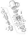
- Fig. 2 is an exploded view of the tool of Fig. 1 .
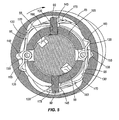
- Fig. 3 is a cross-sectional view along line 3-3 in Fig. 1 .
- Fig. 4 is a perspective cross-sectional view along line 4-4 in Fig. 1 , illustrating a locking assembly in an unlocked position.
- Fig. 5 is a view similar to Fig. 4 , with a collar of the locking assembly moved into a locked position, but locking members of the locking assembly not engaging spindle slots on a of the tool.
- Fig. 6 is a view similar to Figs. 5 , with the spindle having been rotated closer to aligning the spindle slots with the locking members.
- Fig. 7 is a view similar to Fig. 4 , with the locking assembly in a locked position.
- Fig. 1 illustrates a power tool 10, which in the illustrated embodiment is a pneumatic grinder but in other embodiments may be an electric tool 10 or substantially any tool 10 having a rotating spindle.
- the tool 10 includes a housing 15, a spindle assembly 20, a collet assembly 25, and a locking assembly 30.
- the spindle assembly 20 includes a spindle 35 and a bearing 40 supporting the spindle 35 in cantilever fashion for rotation within the housing 15.
- the spindle 35 defines a longitudinal axis 45, which is also its axis of rotation, and has a keyway 50 and a pair of diametrically-opposed spindle slots 55.
- the spindle slots 155 can take on other shapes and sizes, including a round hole, and may be referred to as an orifice, hole or other type of aperture.
- the illustrated embodiment is a right angle grinder, in which a bevel gear is affixed to the spindle 35 by way of a key in the keyway 50.
- the bevel gear meshes at right angles with a pinion that is affixed to an output shaft of the tool's motor.
- the motor shaft is thus generally perpendicular or at a right angle to the longitudinal axis 45 of the spindle 35 in the illustrated embodiment.
- the spindle 35 may be threaded onto or into the output shaft of the motor, which would eliminate the need for the keyway 50.
- the spindle 35 also includes a distal end connected to the collet assembly 25. All illustrated elements of the tool 10 are coaxial with the longitudinal axis 45 unless otherwise specified.
- the collet assembly 25 includes a collet 60 and a collet nut 65.
- the collet nut 65 is threaded onto the distal end of the spindle 35. Rotating the collet nut 65 in a first direction with respect to the spindle 35 causes the collet 60 to open and rotating the collet nut 65 in a second direction, opposite the first direction, with respect to the spindle 35 causes the collet 60 to close.
- Attachments are removed from the collet 60 by rotating the collet nut 65 in the first direction with respect to the spindle 35, and are secured to the collet 60 by rotating the collet nut 65 in the second direction with respect to the spindle 35 until sufficient normal force and surface friction are created between the collet 60 and attachment to couple the attachment and spindle 35 for rotation together during ordinary operating conditions.
- the locking assembly 30 provides a mechanism for coupling the spindle 35 to the housing 15 to prevent rotation of the spindle 35 with respect to the housing 15. Because the housing 15 is relatively large and easy to handle by an operator compared to the spindle 35, the locking assembly 30 provides a means for manually resisting rotation of the spindle 35 (i.e., by manually resisting rotation of the tool housing 15) as a wrench is applied to the collet nut 65 and the collet nut 65 is turned in the first or second directions with respect to the spindle 35 and tool housing 15. This obviates the need for a second wrench applied to the spindle 35 when tightening and loosening the collet nut 65.
- the locking assembly 30 includes a clamp nut 70, a pair of pins 75, a retaining ring 80, a collar 85, a pair of locking members 90, and a pair of biasing members or springs 95.
- the clamp nut 70 includes an enlarged outer diameter male threaded portion 100 and a reduced outer diameter cylindrical portion 105.
- a central bore 110 extends through the threaded portion 100 and cylindrical portion 105 of the clamp nut 70, and the spindle 35 extends through the central bore 110.
- the threaded portion 100 of the clamp nut 70 threads into female threads in the housing 15. When threaded into the housing 15, the clamp nut 70 clamps the bearing 40 within the housing 15.
- the cylindrical portion 105 includes a diametrically-opposed pair of radial openings 120 and a circumferential groove 125.
- the openings 120 can take on other shapes and sizes, including a round hole or slot, and may be referred to as an orifice, hole or other type of aperture.
- the pair of pins 75 are affixed to diametrically-opposed portions of the threaded portion 100 of the clamp nut 70 and extend parallel to the cylindrical portion 105. In other words, the pins 75 extend longitudinally and are spaced from the cylindrical portion 105.
- the collar 85 extends around the cylindrical portion 105 of the clamp nut 70, over the radial openings 120.
- the retaining ring 80 sits in the circumferential groove 125 and retains the collar 85 on the cylindrical portion 105 of the clamp nut 70 (i.e., resists longitudinal movement of the collar 85 off the cylindrical portion 105).
- the collar 85 covers the pins 75, locking members 90, and springs 95.
- the inner surface of the collar 85 includes cam surfaces 130, locked detents 135, and unlocked detents 140 that interact with the springs 95 to cause the locking members 90 to move into and out of engagement with the spindle slots 55.
- the locking members 90 are within the radial openings 120 in the cylindrical portion 105 of the clamp nut 70, and are movable radially (i.e., perpendicular to the longitudinal axis 45) between an unlocked position ( Fig. 4 ) and a locked position ( Fig. 7 ).
- Each locking member 90 includes a spring slot 145.
- the locking members 90 have longitudinal extents that are generally perpendicular to the longitudinal axis 45 of the spindle 35, and for the sake of convenience in this disclosure, an element is said to be parallel or perpendicular to the locking member 90 if it is parallel or perpendicular to the longitudinal extent of the locking member 90.
- the spring slot 145 extends generally parallel to the locking member 90.
- the top of the spring slot 145 is the end furthest from the spindle 35 and the bottom of the spring slot 145 is the end closest to the spindle 35.
- the spring slot 145 is shaped to accommodate the full expected range of angles of the spring 95 with respect to the locking member 90.
- the spring slot 145 can take on other shapes and sizes, including a round hole, and may be referred to as an orifice, hole or other type of aperture.
- the springs 95 are generally elongated and wire-shaped in the illustrated embodiment and in this regard may be referred to as wire springs 95.
- Each spring 95 includes a loop 150, a first end 155 to one side of the loop 150, and a second end 160 on an opposite side of the loop 150.
- the side of the locking member 90 facing generally toward the loop 150 is referred to herein as the "near side” of the locking member 90, and the side of the locking member 90 facing generally away from the loop 150 is referred to herein as the "far side” of the locking member 90.
- the first end 155 is shorter than the second end 160 in the illustrated embodiment.
- the first end 155 includes a detent bend 165.
- the second end 160 includes a cam-following bend 170 that engages the inner cam surface 130 of the collar 85, and a tip 175 that extends through the spring slot 145 in one of the locking members 90.
- the first end 155 of the spring 95 pushes the locking member 90 into the spindle slot 55 with a radially-directed force.
- the second end 160 of the spring 95 is generally perpendicular to the locking member 90, and extends across and acts on the bottom of the spring slot 145.
- the spindle slots 55 will not be in alignment with the radial openings 120 when the collar 85 is rotated into the locked position.
- the locking member 90 is moved radially into abutment with the spindle 35 with the second end 160 of the spring 95 acting on the bottom of the spring slot 145 on the near side of the locking member 90.
- the cam surface 130 pushes on the cam-following bend 170, which pushes the tip 175 of the spring through the spring slot 145 in the locking member 90.
- the second end 160 slides across and pivots on the bottom of the spring slot 145.
- the second end 160 of the spring is non-perpendicular to the locking member 90 and bears against the bottom of the spring slot 145, generally on the near side of the locking member 90.
- the spring 95 therefore acconunodates movement of the collar 85 into the locked position even if the locking member 90 is prevented from moving radially into engagement with the spindle slot 55. This is because neither the cam surface 130 nor any other hard, inflexible surface acts directly on the locking member 90. Instead, a radially-directed biasing force builds up in the spring 95 as the collar 85 is moved into the locked position, such that the locking member 90 immediately snaps into the spindle slot 55 (under the influence of the radial biasing force of the spring 95) when it is rotated into alignment with the locking member 90 (see the sequence of Figs. 5 , 6 , 7 ). It is expected that in most cases, an operator can manually rotate the spindle 35 to align the spindle slot 55 with the locking member 90, and will receive tactile and audible feedback as the locking member 90 snaps into the spindle slot 55.
- the spindle 35 is locked with respect to the housing 15, because the locking members 90 extend through the radial openings 120 of the clamp nut 70, which is threaded into the housing 15.
- a wrench may be applied to the collet nut 65 and the collet nut 65 may be turned with respect to the spindle 35 while the operator conveniently holds the tool housing 15.
- the locking assembly 30 is moved into an unlocked position by rotating the collar 85 in a second, unlocking direction (which is opposite the locking direction or counterclockwise in the illustrated embodiment).
- the operator is given tactile feedback that the locking assembly 30 is in the unlocked position when the detent bends 165 of the springs 95 move into the unlocked detents 140.
- the springs 95 relax as the cam-following bends 170 follow the cam surfaces 130 and pivot radially outwardly. As the springs 95 relax and pivot radially outwardly, they move the locking members 90 radially outwardly, which draws the locking members 90 out of the spindle slots 55. With the locking members 90 out of the spindle slots 55, the spindle 35 is free to rotate in the bearing 40 with respect to the housing 15 and normal operation of the tool 10 (e.g., with a new attachment in the collet 60) may be resumed. In the unlocked position, the springs 95 hold the locking members 90 in the unlocked positions.
- the springs 95 bias the locking members 90 toward the locked position when the locking assembly 30 is in the locked position, and hold or bias the locking members 90 toward the unlocked position when the locking assembly 30 is in the unlocked position.
- the locking members 90 are acted on only by the spring biasing forces and are not directly abutted by the collar 85 or cam surface 130.
- the invention provides, among other things, a locking mechanism for a tool spindle, which includes a biasing member for permitting the locking mechanism to move into the locked position even when the locking member is unable to fully engage the spindle.
Landscapes
- Engineering & Computer Science (AREA)
- Mechanical Engineering (AREA)
- Gripping On Spindles (AREA)
- Jigs For Machine Tools (AREA)
- Axle Suspensions And Sidecars For Cycles (AREA)
- Finish Polishing, Edge Sharpening, And Grinding By Specific Grinding Devices (AREA)
- Snaps, Bayonet Connections, Set Pins, And Snap Rings (AREA)
Claims (7)
- Ensemble de verrouillage de broche (35) définissant un axe longitudinal (45) et comportant une fente de broche (55), la broche (35) étant supportée pour tourner autour de l'axe longitudinal (45) dans un boîtier (15), l'ensemble de verrouillage comprenant:un élément de verrouillage (90) supporté pour effectuer un mouvement perpendiculaire à l'axe longitudinal (45) pour entrer en engagement avec la fente de broche (55) ou en sortir, l'élément de verrouillage (90) empêchant la rotation de la broche (35) par rapport au boîtier (15) lorsqu'il est en engagement avec la fente de broche (55) et permettant la rotation de la broche (35) par rapport au boîtier (15) lorsqu'il est désengagé de la fente de broche (55);un élément de sollicitation (95) interconnecté avec l'élément de verrouillage (90) ; etun collet (85) entourant une partie de la broche (35), le collet (85) incluant au moins une surface de came (130) et pouvant tourner autour de l'axe longitudinal (45) par rapport à la broche (35) et au boîtier (15) entre une position non verrouillée et une position verrouillée;dans lequel la rotation du collet (85) dans la position non verrouillée permet à l'élément de sollicitation (95) de pousser l'élément de verrouillage (90) hors de son engagement avec la fente de broche (55);dans lequel la rotation du collet (85) dans la position verrouillée amène la surface de came (130) à buter contre et à dévier l'élément de sollicitation (95) de sorte que l'élément de sollicitation (95) pousse l'élément de verrouillage (90) dans un engagement avec la fente de la broche (55); etdans lequel l'élément de sollicitation (95) dévie pour permettre la rotation du collet (85) dans la position fermée avec la fente de broche (55) non alignée avec l'élément de verrouillage (90),caractérisé en ce que l'élément de sollicitation (95) inclut une courbure de détente (165), dans lequel le collet (85) inclut en outre une rainure de détente verrouillée (135) et une rainure de détente non verrouillée (140); dans lequel la courbure de détente (165) est reçue dans la rainure de détente verrouillée (135) en réponse à la rotation du collet (85) dans sa position verrouillée pour contrer la rotation du collet (85) quittant la position verrouillée; et dans lequel la courbure de détente (165) est reçue dans la rainure de détente non verrouillée (140) en réponse à la rotation du collet (85) dans la position non verrouillée pour contrer la rotation du collet (85) quittant la position non verrouillée.
- Ensemble de verrouillage selon la revendication 1, comprenant en outre un écrou de serrage (70) fixé par rotation par rapport au boîtier (15), l'écrou de serrage (70) incluant une partie cylindrique (105) définissant un alésage central (110) à travers lequel la broche (35) s'étend; dans lequel la partie cylindrique (105) inclut une ouverture radiale (120) à travers laquelle l'élément de verrouillage (90) peut être déplacé pour s'engager dans la fente de broche (55) lorsque la fente de broche (55) est alignée avec l'ouverture radiale (120).
- Ensemble de verrouillage selon la revendication 1 ou 2, dans lequel l'élément de sollicitation (95) inclut une partie (160, 170, 175) s'étendant à travers l'élément de verrouillage (90) et butant contre et suivant la surface de came (130) lorsque le collet (85) tourne dans sa position verrouillée.
- Ensemble de verrouillage selon l'une quelconque des revendications précédentes, dans lequel l'élément de sollicitation (95) inclut une section de pivot (150) qui est supporté de manière pivotable par rapport au boîtier (15), de sorte que l'élément de sollicitation (95) pivote sur la section de pivot (150) lorsque le collet (85) est tourné entre les positions verrouillée et non verrouillée.
- Ensemble de verrouillage selon la revendication 1, dans lequel l'élément de sollicitation (95) inclut un ressort à fil ayant une première extrémité (160) s'étendant à travers l'élément de verrouillage (90) et butant contre et suivant la surface de came (130) lorsque le collet (85) est tourné dans la position fermée ;
dans lequel l'élément de sollicitation (95) inclut en outre une deuxième extrémité (155) définissant la courbure de détente (165);
dans lequel l'élément de sollicitation (95) inclut en outre une section de pivot (150) entre les première et deuxième extrémités (155, 160), la section de pivot (150) étant supportée de manière pivotable par rapport au boîtier (15), de sorte que l'élément de sollicitation (95) pivote autour de la section de pivot (150) lorsque le collet (85) tourne entre les positions verrouillée et non verrouillée. - Ensemble de verrouillage selon la revendication 4, comprenant en outre une tige de support à pivot (75) fixée par rapport au boîtier (15); dans lequel la section de pivot inclut une boucle (150) dans le ressort à fil (95); et dans lequel la boucle (150) s'étend autour de la tige de support à pivot (75) de sorte que la tige de support à pivot (75) supporte le ressort à fil (95) pour son pivotement lorsque le collet (85) est tourné entre les positions verrouillée et non verrouillée.
- Outil comprenant :un boîtier (15);une broche (35) définissant un axe longitudinal (45) et ayant une fente de broche (55), la broche (35) étant supportée pour tourner autour de l'axe longitudinal (45) dans le boîtier (15); etun ensemble de verrouillage (30) selon l'une quelconque des revendications précédentes.
Applications Claiming Priority (2)
| Application Number | Priority Date | Filing Date | Title |
|---|---|---|---|
| US12/418,205 US8011444B2 (en) | 2009-04-03 | 2009-04-03 | Spindle locking assembly |
| PCT/US2010/026657 WO2010114681A1 (fr) | 2009-04-03 | 2010-03-09 | Ensemble de verrouillage d'axe |
Publications (3)
| Publication Number | Publication Date |
|---|---|
| EP2414121A1 EP2414121A1 (fr) | 2012-02-08 |
| EP2414121A4 EP2414121A4 (fr) | 2012-09-26 |
| EP2414121B1 true EP2414121B1 (fr) | 2013-07-31 |
Family
ID=42825244
Family Applications (1)
| Application Number | Title | Priority Date | Filing Date |
|---|---|---|---|
| EP10759184.4A Not-in-force EP2414121B1 (fr) | 2009-04-03 | 2010-03-09 | Ensemble de verrouillage d'axe |
Country Status (4)
| Country | Link |
|---|---|
| US (1) | US8011444B2 (fr) |
| EP (1) | EP2414121B1 (fr) |
| CN (1) | CN102378660B (fr) |
| WO (1) | WO2010114681A1 (fr) |
Families Citing this family (14)
| Publication number | Priority date | Publication date | Assignee | Title |
|---|---|---|---|---|
| US8056431B2 (en) * | 2008-09-08 | 2011-11-15 | Stanley Ackerman | Self-locking gear |
| EP2544862B1 (fr) * | 2010-03-08 | 2016-04-06 | Techtronic Power Tools Technology Limited | Outil électrique comprenant un dispositif de blocage de broche |
| DE102011005553A1 (de) * | 2010-10-15 | 2012-04-19 | Robert Bosch Gmbh | Handgeführtes Elektrowerkzeug mit einer Spindellockvorrichtung |
| DE102010043746A1 (de) * | 2010-11-11 | 2012-05-16 | Robert Bosch Gmbh | Handwerkzeugmaschine mit einer Spindellockvorrichtung |
| US20130299207A1 (en) * | 2012-05-10 | 2013-11-14 | Black & Decker, Inc. | Power tool cooling |
| DE102013212193A1 (de) * | 2013-06-26 | 2014-12-31 | Robert Bosch Gmbh | Handwerkzeugmaschine mit einer Spindellockvorrichtung |
| US10813692B2 (en) * | 2016-02-29 | 2020-10-27 | Covidien Lp | 90-degree interlocking geometry for introducer for facilitating deployment of microwave radiating catheter |
| DE102016118766A1 (de) * | 2016-10-04 | 2018-04-05 | Wto Vermögensverwaltung Gmbh | Bohr-Fräs-Einrichtung mit einer Einrichtung zur Vergleichmäßigung von Drehmoment und Drehzahl der Spindel |
| CN207189852U (zh) | 2017-06-05 | 2018-04-06 | 米沃奇电动工具公司 | 台锯 |
| US10856944B2 (en) * | 2018-11-05 | 2020-12-08 | Hiwin Technologies Corp. | Triaxial motion device |
| US10850358B2 (en) * | 2018-11-30 | 2020-12-01 | G.A.W. Inc. | Spindle locking apparatus for a rotary power tool |
| CA3122613C (fr) * | 2018-12-11 | 2023-04-04 | Techtronic Cordless Gp | Connecteur pour fixation de couplage a un outil electrique |
| TWI716257B (zh) * | 2020-01-10 | 2021-01-11 | 欣特實業股份有限公司 | 轉軸鎖定裝置 |
| US12102369B2 (en) * | 2021-05-13 | 2024-10-01 | DePuy Synthes Products, Inc. | Surgical impacting tool interfaces |
Family Cites Families (68)
| Publication number | Priority date | Publication date | Assignee | Title |
|---|---|---|---|---|
| US1497483A (en) * | 1921-07-21 | 1924-06-10 | Edward T Callender | Drill chuck |
| US2395534A (en) * | 1944-05-24 | 1946-02-26 | Lloyd W Miller | Chuck |
| US2612377A (en) * | 1950-08-01 | 1952-09-30 | Ralph A Edens | Toolholder for tapered shanked tools |
| US2731273A (en) * | 1955-05-23 | 1956-01-17 | Falcon Tool Company | Tool holders |
| CH324773A (fr) * | 1955-06-25 | 1957-10-15 | Christen & Cie Ag | Mandrin pour machine-outil |
| US3044091A (en) * | 1960-04-22 | 1962-07-17 | Nishihama Archie Akira | Tool attaching means for circular rubbing machines |
| US3179965A (en) * | 1961-10-26 | 1965-04-27 | Khachigian John | Drilling and threading attachment |
| US3334448A (en) * | 1964-03-20 | 1967-08-08 | Rockwell Mfg Co | Spindle lock for a power tool |
| US3527466A (en) * | 1968-11-25 | 1970-09-08 | Devlieg Machine Co | Axially adjustable chuck |
| US3679244A (en) * | 1970-09-21 | 1972-07-25 | Robert R Reddy | Releasable shaft lock |
| US3747946A (en) * | 1970-12-21 | 1973-07-24 | R Edens | Tool holders |
| US3743307A (en) * | 1971-07-15 | 1973-07-03 | Erickson Tool Co | Spring actuated chuck |
| DE2136523C3 (de) * | 1971-07-21 | 1983-11-03 | Hilti AG, 9494 Schaan | Elektrobohrhammer |
| US3802518A (en) * | 1972-03-09 | 1974-04-09 | J Albert | Ratchet implement |
| US3872951A (en) * | 1973-11-06 | 1975-03-25 | Black & Decker Mfg Co | Spindle locking mechanism for rotary power device |
| US4078589A (en) * | 1976-05-10 | 1978-03-14 | Miller Walter L | Battery driven screwdriver |
| US4204303A (en) * | 1977-12-05 | 1980-05-27 | Eidam Lane L P | Locking mechanism for machine tool holder/adapter |
| US4400995A (en) * | 1981-09-23 | 1983-08-30 | Milwaukee Electric Tool Corporation | Spindle lock with impacting capability |
| DE3142617A1 (de) * | 1981-10-28 | 1983-05-05 | Robert Bosch Gmbh, 7000 Stuttgart | Rasteinrichtung |
| US4526497A (en) * | 1982-03-15 | 1985-07-02 | Hatfield Jim J | Automatic jaw control for reversible power tool |
| JPS58177604A (ja) * | 1982-04-10 | 1983-10-18 | 佐藤 裕二 | 移動棚のロツク装置 |
| US4804048A (en) * | 1983-02-04 | 1989-02-14 | Skil Corporation | Hand-held tool with shaft lock |
| US4467896A (en) * | 1983-06-17 | 1984-08-28 | Black & Decker Inc. | Locking mechanism for a rotary power machine |
| US4489525A (en) * | 1983-08-11 | 1984-12-25 | Black & Decker Inc. | Replaceable spindle lock system |
| DE3405980A1 (de) * | 1984-02-18 | 1985-08-22 | Günter Horst 7927 Sontheim Röhm | Schlagbohreinrichtung |
| US4563116A (en) * | 1984-05-16 | 1986-01-07 | Edens Rudolph R | Tool holder with coolant inducer |
| DE3447154C2 (de) * | 1984-12-22 | 1998-02-19 | Stihl Maschf Andreas | Drehsicherung für ein drehbar gelagertes Werkzeug, insbesondere ein Schneidwerkzeug eines Freischneidegerätes |
| EP0194426B1 (fr) * | 1985-03-14 | 1988-03-23 | Günter Horst Röhm | Mandrin pour forage rotatif ou à percussion rotative |
| FR2598110B2 (fr) * | 1985-10-24 | 1989-11-03 | Black & Decker Inc | Tournevis motorise perfectionne |
| DE3636027A1 (de) * | 1986-10-23 | 1988-04-28 | Hilti Ag | Handgeraet mit loesbarem werkzeughalter |
| US4919023A (en) * | 1988-03-22 | 1990-04-24 | Bloink Harry W | Quick-change tool adapter |
| US5016501B1 (en) * | 1988-07-29 | 1997-07-15 | Sb Power Tool Co | Automatic shaft lock |
| US5156244A (en) * | 1990-08-31 | 1992-10-20 | The Aro Corporation | Torque sensing automatic shut-off and reset clutch for screwdrivers, nutsetters and the like |
| DE4105340C2 (de) | 1991-02-21 | 1993-09-30 | Atlas Copco Elektrowerkzeuge | Handgeführter Winkelschleifer mit einer Bremsanordnung und einer eine Stirnverzahnung oder dergleichen formschlüssige Verbindung aufweisenden Einrichtung zum Sichern des Spannflansches gegen selbsttätiges Lösen beim Bremsvorgang |
| US5191968A (en) * | 1991-09-23 | 1993-03-09 | Ryobi Motor Products Corp. | Shaft lock arrangement for a power tool |
| US5496139A (en) * | 1994-09-19 | 1996-03-05 | Snap-On Incorporated | Collet lock arrangement for power tool |
| US5820135A (en) * | 1996-03-01 | 1998-10-13 | Power Tool Holders Incorporated | Counter centrifugal chuck and mounting systems |
| US5810366A (en) * | 1996-06-19 | 1998-09-22 | Power Tool Holders Incorporated | Tool-less machine tool chuck |
| US5951026A (en) * | 1997-12-12 | 1999-09-14 | Black & Decker Inc. | Removable chuck |
| US6079716A (en) * | 1997-12-12 | 2000-06-27 | Black & Decker Inc. | Removable chuck |
| US6688611B2 (en) * | 1997-12-12 | 2004-02-10 | Black & Decker Inc. | Removable chuck |
| US6550786B2 (en) * | 1997-12-12 | 2003-04-22 | Black & Decker Inc. | Removable chuck |
| US6261036B1 (en) * | 1998-11-16 | 2001-07-17 | Porter-Cable Corporation | Plunge router locking system |
| US6223833B1 (en) * | 1999-06-03 | 2001-05-01 | One World Technologies, Inc. | Spindle lock and chipping mechanism for hammer drill |
| US6273200B1 (en) * | 1999-07-07 | 2001-08-14 | Black & Decker Inc. | Screwdriver with manuel spindel lock |
| US6485360B1 (en) * | 1999-07-20 | 2002-11-26 | Hutchins Mfg, Co. | Orbital sanding tool |
| US6729812B2 (en) * | 1999-12-06 | 2004-05-04 | Theodore G. Yaksich | Power driver having geared tool holder |
| CA2339430A1 (fr) * | 2000-03-10 | 2001-09-10 | Black & Decker Inc. | Marteau |
| DE10029898A1 (de) * | 2000-06-17 | 2001-12-20 | Bosch Gmbh Robert | Handwerkzeugmaschine |
| US6350087B1 (en) * | 2000-07-07 | 2002-02-26 | Black & Decker Inc. | Tool-free collet tightener |
| GB0026051D0 (en) | 2000-10-25 | 2000-12-13 | Universal Drilling And Cutting | Arbor |
| US6939213B2 (en) * | 2002-03-25 | 2005-09-06 | Lhr Technologies, Inc. | Quick change adaptor for rotary machines |
| GB2394516A (en) * | 2002-10-23 | 2004-04-28 | Black & Decker Inc | Power tool |
| US7052022B2 (en) * | 2003-05-13 | 2006-05-30 | Snap-On Incorporated | Chuck for pneumatic hammer |
| US7325812B2 (en) * | 2003-05-14 | 2008-02-05 | Eastway Fair Company Limited | Grip assembly for clutch cap, front sleeve, rear sleeve and method of making |
| US6974370B2 (en) * | 2003-05-16 | 2005-12-13 | Hutchins Manufacturing Company | Spindle lock for an orbital abrading or polishing tool |
| US6886643B2 (en) * | 2003-09-05 | 2005-05-03 | Credo Technology Corporation | Shaft lock mechanism for a rotary power hand tool |
| GB2408707A (en) * | 2003-12-04 | 2005-06-08 | Black & Decker Inc | Chuck |
| US7344141B2 (en) * | 2004-01-30 | 2008-03-18 | Black & Decker Inc. | Collet system for rotary tools |
| US7455302B2 (en) * | 2004-08-09 | 2008-11-25 | The Jacobs Chuck Manufacturing Company | Chuck with spindle lock |
| US7264429B2 (en) * | 2004-09-24 | 2007-09-04 | Black & Decker Inc. | Tool free collet assembly |
| US7588398B2 (en) * | 2005-04-19 | 2009-09-15 | Black & Decker Inc. | Tool chuck with power take off and dead spindle features |
| US20060232023A1 (en) * | 2005-04-19 | 2006-10-19 | Yaksich Theodore G | Chuck with improved sleeve |
| US7472913B2 (en) * | 2005-06-09 | 2009-01-06 | Jacobs Chuck Manufacturing Company | Drill chuck |
| DE602006013863D1 (de) * | 2005-11-04 | 2010-06-02 | Bosch Gmbh Robert | Verfahren und vorrichtung für einen gelenkbohrer |
| JP4754395B2 (ja) * | 2006-04-20 | 2011-08-24 | 株式会社マキタ | ねじ締め機 |
| SE529928C2 (sv) | 2006-05-09 | 2008-01-08 | Atlas Copco Tools Ab | Låsanordning för portabelt verktyg |
| US20080014844A1 (en) * | 2006-07-17 | 2008-01-17 | James Matthew Pontieri | Power tool with spindle lock |
-
2009
- 2009-04-03 US US12/418,205 patent/US8011444B2/en not_active Expired - Fee Related
-
2010
- 2010-03-09 CN CN2010800148526A patent/CN102378660B/zh not_active Expired - Fee Related
- 2010-03-09 EP EP10759184.4A patent/EP2414121B1/fr not_active Not-in-force
- 2010-03-09 WO PCT/US2010/026657 patent/WO2010114681A1/fr not_active Ceased
Also Published As
| Publication number | Publication date |
|---|---|
| US20100252292A1 (en) | 2010-10-07 |
| EP2414121A4 (fr) | 2012-09-26 |
| EP2414121A1 (fr) | 2012-02-08 |
| CN102378660A (zh) | 2012-03-14 |
| US8011444B2 (en) | 2011-09-06 |
| WO2010114681A1 (fr) | 2010-10-07 |
| CN102378660B (zh) | 2013-11-27 |
Similar Documents
| Publication | Publication Date | Title |
|---|---|---|
| EP2414121B1 (fr) | Ensemble de verrouillage d'axe | |
| US8650992B2 (en) | Driver accessory | |
| US9518678B2 (en) | Electrical feedback device for valves | |
| US9403225B2 (en) | Miter saw | |
| CN106475974B (zh) | 手持式工具及其夹紧装置 | |
| US6533291B2 (en) | Chuck having quick change mechanism | |
| US12030170B2 (en) | Electric power tool | |
| JP5396149B2 (ja) | 動力工具 | |
| US20190255713A1 (en) | Robotic End-of-Arm Manual Tool Changer | |
| US20040135325A1 (en) | Chuck with locking system | |
| JP2007229914A (ja) | シーケンスの径方向並びに軸線方向のロック手段が設けられた、回転マシンを装備するための工具把持用のチャック | |
| CN112654464A (zh) | 模块化工具装置 | |
| ES2991482T3 (es) | Alicate de pico de loro | |
| US9604385B2 (en) | Electric trimmer | |
| CN101340996B (zh) | 钻卡头 | |
| US7556269B2 (en) | Tool-carrier chuck for rotating machine, furnished with locking means | |
| EP3243446A1 (fr) | Ensembles d'adaptateur pour dispositifs chirurgicaux | |
| JP2024012564A (ja) | 工具 | |
| EP3764193B1 (fr) | Dispositif à main et perforatrice | |
| JP4693099B2 (ja) | 管継手 | |
| EP4671104A1 (fr) | Élément tubulaire et ensemble de montage de support | |
| WO2009064187A1 (fr) | Dispositif pour maintenir un dispositif auxiliaire à angle droit par rapport à un axe de rotation imaginaire | |
| JP2014073572A (ja) | トルクレンチ |
Legal Events
| Date | Code | Title | Description |
|---|---|---|---|
| PUAI | Public reference made under article 153(3) epc to a published international application that has entered the european phase |
Free format text: ORIGINAL CODE: 0009012 |
|
| 17P | Request for examination filed |
Effective date: 20111006 |
|
| AK | Designated contracting states |
Kind code of ref document: A1 Designated state(s): AT BE BG CH CY CZ DE DK EE ES FI FR GB GR HR HU IE IS IT LI LT LU LV MC MK MT NL NO PL PT RO SE SI SK SM TR |
|
| DAX | Request for extension of the european patent (deleted) | ||
| A4 | Supplementary search report drawn up and despatched |
Effective date: 20120828 |
|
| RIC1 | Information provided on ipc code assigned before grant |
Ipc: B23B 31/00 20060101AFI20120822BHEP |
|
| GRAP | Despatch of communication of intention to grant a patent |
Free format text: ORIGINAL CODE: EPIDOSNIGR1 |
|
| GRAS | Grant fee paid |
Free format text: ORIGINAL CODE: EPIDOSNIGR3 |
|
| GRAP | Despatch of communication of intention to grant a patent |
Free format text: ORIGINAL CODE: EPIDOSNIGR1 |
|
| GRAA | (expected) grant |
Free format text: ORIGINAL CODE: 0009210 |
|
| INTG | Intention to grant announced |
Effective date: 20130612 |
|
| RAP1 | Party data changed (applicant data changed or rights of an application transferred) |
Owner name: INGERSOLL-RAND COMPANY |
|
| AK | Designated contracting states |
Kind code of ref document: B1 Designated state(s): AT BE BG CH CY CZ DE DK EE ES FI FR GB GR HR HU IE IS IT LI LT LU LV MC MK MT NL NO PL PT RO SE SI SK SM TR |
|
| REG | Reference to a national code |
Ref country code: GB Ref legal event code: FG4D Ref country code: CH Ref legal event code: EP |
|
| REG | Reference to a national code |
Ref country code: AT Ref legal event code: REF Ref document number: 624315 Country of ref document: AT Kind code of ref document: T Effective date: 20130815 |
|
| REG | Reference to a national code |
Ref country code: IE Ref legal event code: FG4D |
|
| REG | Reference to a national code |
Ref country code: DE Ref legal event code: R096 Ref document number: 602010009100 Country of ref document: DE Effective date: 20130926 |
|
| REG | Reference to a national code |
Ref country code: AT Ref legal event code: MK05 Ref document number: 624315 Country of ref document: AT Kind code of ref document: T Effective date: 20130731 |
|
| REG | Reference to a national code |
Ref country code: NL Ref legal event code: VDEP Effective date: 20130731 |
|
| REG | Reference to a national code |
Ref country code: LT Ref legal event code: MG4D |
|
| PG25 | Lapsed in a contracting state [announced via postgrant information from national office to epo] |
Ref country code: CY Free format text: LAPSE BECAUSE OF FAILURE TO SUBMIT A TRANSLATION OF THE DESCRIPTION OR TO PAY THE FEE WITHIN THE PRESCRIBED TIME-LIMIT Effective date: 20130807 Ref country code: AT Free format text: LAPSE BECAUSE OF FAILURE TO SUBMIT A TRANSLATION OF THE DESCRIPTION OR TO PAY THE FEE WITHIN THE PRESCRIBED TIME-LIMIT Effective date: 20130731 Ref country code: BE Free format text: LAPSE BECAUSE OF FAILURE TO SUBMIT A TRANSLATION OF THE DESCRIPTION OR TO PAY THE FEE WITHIN THE PRESCRIBED TIME-LIMIT Effective date: 20130731 Ref country code: SE Free format text: LAPSE BECAUSE OF FAILURE TO SUBMIT A TRANSLATION OF THE DESCRIPTION OR TO PAY THE FEE WITHIN THE PRESCRIBED TIME-LIMIT Effective date: 20130731 Ref country code: PT Free format text: LAPSE BECAUSE OF FAILURE TO SUBMIT A TRANSLATION OF THE DESCRIPTION OR TO PAY THE FEE WITHIN THE PRESCRIBED TIME-LIMIT Effective date: 20131202 Ref country code: LT Free format text: LAPSE BECAUSE OF FAILURE TO SUBMIT A TRANSLATION OF THE DESCRIPTION OR TO PAY THE FEE WITHIN THE PRESCRIBED TIME-LIMIT Effective date: 20130731 Ref country code: IS Free format text: LAPSE BECAUSE OF FAILURE TO SUBMIT A TRANSLATION OF THE DESCRIPTION OR TO PAY THE FEE WITHIN THE PRESCRIBED TIME-LIMIT Effective date: 20131130 Ref country code: NO Free format text: LAPSE BECAUSE OF FAILURE TO SUBMIT A TRANSLATION OF THE DESCRIPTION OR TO PAY THE FEE WITHIN THE PRESCRIBED TIME-LIMIT Effective date: 20131031 Ref country code: HR Free format text: LAPSE BECAUSE OF FAILURE TO SUBMIT A TRANSLATION OF THE DESCRIPTION OR TO PAY THE FEE WITHIN THE PRESCRIBED TIME-LIMIT Effective date: 20130731 |
|
| PG25 | Lapsed in a contracting state [announced via postgrant information from national office to epo] |
Ref country code: LV Free format text: LAPSE BECAUSE OF FAILURE TO SUBMIT A TRANSLATION OF THE DESCRIPTION OR TO PAY THE FEE WITHIN THE PRESCRIBED TIME-LIMIT Effective date: 20130731 Ref country code: NL Free format text: LAPSE BECAUSE OF FAILURE TO SUBMIT A TRANSLATION OF THE DESCRIPTION OR TO PAY THE FEE WITHIN THE PRESCRIBED TIME-LIMIT Effective date: 20130731 Ref country code: GR Free format text: LAPSE BECAUSE OF FAILURE TO SUBMIT A TRANSLATION OF THE DESCRIPTION OR TO PAY THE FEE WITHIN THE PRESCRIBED TIME-LIMIT Effective date: 20131101 Ref country code: SI Free format text: LAPSE BECAUSE OF FAILURE TO SUBMIT A TRANSLATION OF THE DESCRIPTION OR TO PAY THE FEE WITHIN THE PRESCRIBED TIME-LIMIT Effective date: 20130731 Ref country code: PL Free format text: LAPSE BECAUSE OF FAILURE TO SUBMIT A TRANSLATION OF THE DESCRIPTION OR TO PAY THE FEE WITHIN THE PRESCRIBED TIME-LIMIT Effective date: 20130731 Ref country code: FI Free format text: LAPSE BECAUSE OF FAILURE TO SUBMIT A TRANSLATION OF THE DESCRIPTION OR TO PAY THE FEE WITHIN THE PRESCRIBED TIME-LIMIT Effective date: 20130731 |
|
| PG25 | Lapsed in a contracting state [announced via postgrant information from national office to epo] |
Ref country code: CY Free format text: LAPSE BECAUSE OF FAILURE TO SUBMIT A TRANSLATION OF THE DESCRIPTION OR TO PAY THE FEE WITHIN THE PRESCRIBED TIME-LIMIT Effective date: 20130731 |
|
| PG25 | Lapsed in a contracting state [announced via postgrant information from national office to epo] |
Ref country code: EE Free format text: LAPSE BECAUSE OF FAILURE TO SUBMIT A TRANSLATION OF THE DESCRIPTION OR TO PAY THE FEE WITHIN THE PRESCRIBED TIME-LIMIT Effective date: 20130731 Ref country code: DK Free format text: LAPSE BECAUSE OF FAILURE TO SUBMIT A TRANSLATION OF THE DESCRIPTION OR TO PAY THE FEE WITHIN THE PRESCRIBED TIME-LIMIT Effective date: 20130731 Ref country code: SK Free format text: LAPSE BECAUSE OF FAILURE TO SUBMIT A TRANSLATION OF THE DESCRIPTION OR TO PAY THE FEE WITHIN THE PRESCRIBED TIME-LIMIT Effective date: 20130731 Ref country code: RO Free format text: LAPSE BECAUSE OF FAILURE TO SUBMIT A TRANSLATION OF THE DESCRIPTION OR TO PAY THE FEE WITHIN THE PRESCRIBED TIME-LIMIT Effective date: 20130731 Ref country code: CZ Free format text: LAPSE BECAUSE OF FAILURE TO SUBMIT A TRANSLATION OF THE DESCRIPTION OR TO PAY THE FEE WITHIN THE PRESCRIBED TIME-LIMIT Effective date: 20130731 |
|
| PG25 | Lapsed in a contracting state [announced via postgrant information from national office to epo] |
Ref country code: ES Free format text: LAPSE BECAUSE OF FAILURE TO SUBMIT A TRANSLATION OF THE DESCRIPTION OR TO PAY THE FEE WITHIN THE PRESCRIBED TIME-LIMIT Effective date: 20130731 |
|
| PLBE | No opposition filed within time limit |
Free format text: ORIGINAL CODE: 0009261 |
|
| STAA | Information on the status of an ep patent application or granted ep patent |
Free format text: STATUS: NO OPPOSITION FILED WITHIN TIME LIMIT |
|
| 26N | No opposition filed |
Effective date: 20140502 |
|
| REG | Reference to a national code |
Ref country code: DE Ref legal event code: R097 Ref document number: 602010009100 Country of ref document: DE Effective date: 20140502 |
|
| PG25 | Lapsed in a contracting state [announced via postgrant information from national office to epo] |
Ref country code: LU Free format text: LAPSE BECAUSE OF FAILURE TO SUBMIT A TRANSLATION OF THE DESCRIPTION OR TO PAY THE FEE WITHIN THE PRESCRIBED TIME-LIMIT Effective date: 20140309 |
|
| REG | Reference to a national code |
Ref country code: CH Ref legal event code: PL |
|
| REG | Reference to a national code |
Ref country code: IE Ref legal event code: MM4A |
|
| PG25 | Lapsed in a contracting state [announced via postgrant information from national office to epo] |
Ref country code: LI Free format text: LAPSE BECAUSE OF NON-PAYMENT OF DUE FEES Effective date: 20140331 Ref country code: CH Free format text: LAPSE BECAUSE OF NON-PAYMENT OF DUE FEES Effective date: 20140331 Ref country code: IE Free format text: LAPSE BECAUSE OF NON-PAYMENT OF DUE FEES Effective date: 20140309 |
|
| PGFP | Annual fee paid to national office [announced via postgrant information from national office to epo] |
Ref country code: DE Payment date: 20150219 Year of fee payment: 6 |
|
| PGFP | Annual fee paid to national office [announced via postgrant information from national office to epo] |
Ref country code: GB Payment date: 20150226 Year of fee payment: 6 |
|
| REG | Reference to a national code |
Ref country code: FR Ref legal event code: PLFP Year of fee payment: 7 |
|
| PG25 | Lapsed in a contracting state [announced via postgrant information from national office to epo] |
Ref country code: MT Free format text: LAPSE BECAUSE OF FAILURE TO SUBMIT A TRANSLATION OF THE DESCRIPTION OR TO PAY THE FEE WITHIN THE PRESCRIBED TIME-LIMIT Effective date: 20130731 |
|
| PG25 | Lapsed in a contracting state [announced via postgrant information from national office to epo] |
Ref country code: SM Free format text: LAPSE BECAUSE OF FAILURE TO SUBMIT A TRANSLATION OF THE DESCRIPTION OR TO PAY THE FEE WITHIN THE PRESCRIBED TIME-LIMIT Effective date: 20130731 |
|
| PG25 | Lapsed in a contracting state [announced via postgrant information from national office to epo] |
Ref country code: MC Free format text: LAPSE BECAUSE OF FAILURE TO SUBMIT A TRANSLATION OF THE DESCRIPTION OR TO PAY THE FEE WITHIN THE PRESCRIBED TIME-LIMIT Effective date: 20130731 |
|
| PG25 | Lapsed in a contracting state [announced via postgrant information from national office to epo] |
Ref country code: BG Free format text: LAPSE BECAUSE OF FAILURE TO SUBMIT A TRANSLATION OF THE DESCRIPTION OR TO PAY THE FEE WITHIN THE PRESCRIBED TIME-LIMIT Effective date: 20130731 |
|
| PG25 | Lapsed in a contracting state [announced via postgrant information from national office to epo] |
Ref country code: HU Free format text: LAPSE BECAUSE OF FAILURE TO SUBMIT A TRANSLATION OF THE DESCRIPTION OR TO PAY THE FEE WITHIN THE PRESCRIBED TIME-LIMIT; INVALID AB INITIO Effective date: 20100309 Ref country code: TR Free format text: LAPSE BECAUSE OF FAILURE TO SUBMIT A TRANSLATION OF THE DESCRIPTION OR TO PAY THE FEE WITHIN THE PRESCRIBED TIME-LIMIT Effective date: 20130731 |
|
| REG | Reference to a national code |
Ref country code: DE Ref legal event code: R119 Ref document number: 602010009100 Country of ref document: DE |
|
| GBPC | Gb: european patent ceased through non-payment of renewal fee |
Effective date: 20160309 |
|
| PG25 | Lapsed in a contracting state [announced via postgrant information from national office to epo] |
Ref country code: GB Free format text: LAPSE BECAUSE OF NON-PAYMENT OF DUE FEES Effective date: 20160309 Ref country code: DE Free format text: LAPSE BECAUSE OF NON-PAYMENT OF DUE FEES Effective date: 20161001 |
|
| REG | Reference to a national code |
Ref country code: FR Ref legal event code: PLFP Year of fee payment: 8 |
|
| REG | Reference to a national code |
Ref country code: FR Ref legal event code: PLFP Year of fee payment: 9 |
|
| PG25 | Lapsed in a contracting state [announced via postgrant information from national office to epo] |
Ref country code: MK Free format text: LAPSE BECAUSE OF FAILURE TO SUBMIT A TRANSLATION OF THE DESCRIPTION OR TO PAY THE FEE WITHIN THE PRESCRIBED TIME-LIMIT Effective date: 20130731 |
|
| PGFP | Annual fee paid to national office [announced via postgrant information from national office to epo] |
Ref country code: IT Payment date: 20200218 Year of fee payment: 11 |
|
| PGFP | Annual fee paid to national office [announced via postgrant information from national office to epo] |
Ref country code: FR Payment date: 20200220 Year of fee payment: 11 |
|
| PG25 | Lapsed in a contracting state [announced via postgrant information from national office to epo] |
Ref country code: FR Free format text: LAPSE BECAUSE OF NON-PAYMENT OF DUE FEES Effective date: 20210331 |
|
| PG25 | Lapsed in a contracting state [announced via postgrant information from national office to epo] |
Ref country code: IT Free format text: LAPSE BECAUSE OF NON-PAYMENT OF DUE FEES Effective date: 20210309 |