EP2415501A1 - Fixation pour système de sécurité - Google Patents
Fixation pour système de sécurité Download PDFInfo
- Publication number
- EP2415501A1 EP2415501A1 EP10171902A EP10171902A EP2415501A1 EP 2415501 A1 EP2415501 A1 EP 2415501A1 EP 10171902 A EP10171902 A EP 10171902A EP 10171902 A EP10171902 A EP 10171902A EP 2415501 A1 EP2415501 A1 EP 2415501A1
- Authority
- EP
- European Patent Office
- Prior art keywords
- connector
- mounting
- support post
- respect
- stem
- Prior art date
- Legal status (The legal status is an assumption and is not a legal conclusion. Google has not performed a legal analysis and makes no representation as to the accuracy of the status listed.)
- Granted
Links
Images


Classifications
-
- A—HUMAN NECESSITIES
- A62—LIFE-SAVING; FIRE-FIGHTING
- A62B—DEVICES, APPARATUS OR METHODS FOR LIFE-SAVING
- A62B35/00—Safety belts or body harnesses; Similar equipment for limiting displacement of the human body, especially in case of sudden changes of motion
-
- A—HUMAN NECESSITIES
- A62—LIFE-SAVING; FIRE-FIGHTING
- A62B—DEVICES, APPARATUS OR METHODS FOR LIFE-SAVING
- A62B1/00—Devices for lowering persons from buildings or the like
- A62B1/02—Devices for lowering persons from buildings or the like by making use of rescue cages, bags, or the like
- A62B1/04—Single parts, e.g. fastening devices
Definitions
- This invention relates to a mounting for a safety system, and more specifically to a mounting for a safety system for persons working at height, utilising an anchor arrangement, which in use is to be secured to an uneven, non-uniform profiled surface of a structure.
- the invention has particular applicability to situations in which safety systems need to be installed for working at height on structures such as aircraft wings in which the surface upon which the operatives are working is uneven, curve profiled, undulating, or otherwise non-uniform.
- the invention also has application in other situations and particularly provides a mounting that has a high degree of flexibility in terms of its range of use.
- a prior art safety system for use on aircraft wings is disclosed in, for example, US6607054 .
- a series of vacuum anchor devices are secured to a structure such as an aircraft wing and arranged to support a guardrail or barrier arrangement comprising upright posts which have respective stems inserted into a receiving socket in the vacuum anchor.
- Vacuum anchor devices are well known in the art for anchoring safety lines, barriers or other systems to thin skinned structures such as aircraft wings.
- cross-members span between the upright posts to provide the guardrail or barrier restraint.
- a mounting for a support post of a safety system comprising:
- the connector is mounted to be movable pivotally or rotationally with respect to the stem.
- the connecter is articulated with respect to the stem to be movable about an articulation axis, which articulation axis is transverse to the longitudinal axis of the stem.
- the connector is mounted to a pivot formation (such as a bolt for example), which extends transverse to the longitudinal axis of the stem.
- a pivot formation such as a bolt for example
- a gimballed connection or ball and socket joint could be utilised to give the required articulation range of movement.
- the connector includes a socket for receiving an end of the support post.
- the connector preferably includes a releasable faster for releasable fastening of the support post with the connector.
- the securing means comprises may comprise one or more mechanical fixings arranged to be movable to abut against the connector.
- the mechanical fixings are provided on opposed sides of an articulation joint such as a pivot or hinge axis about which the connector pivots, hinges or otherwise rotatably moves.
- the mechanical fixings may comprise elongate projections and beneficially may be adjustable in terms of their projection distance toward or away from the connector, in order to enable the connector to be secured at different specific attitude orientations.
- the mechanical fixings are arranged to abut against the connector above the level of an articulation joint such as a pivot or hinge axis about which the connector pivots, hinges or otherwise rotatably moves.
- the mechanical fixings may comprise elongate members, movable in their longitudinal direction and are arranged to extend inclined upwardly and have an end arranged to abut against the connector.
- the invention provides a safety system comprising:
- the mounting is articulated to enable the orientation angle of the support post to be adjusted with respect to the anchor device.
- the anchor device comprises a vacuum anchor device.
- the cylindrical stem of the mounting is preferably received in the cylindrical socket of the anchor so as to be rotatable about the longitudinal axis of the stem.
- the safety system of the invention may further include a plurality of barrier guardrails arranged to extend between adjacent upright posts in the system, the barrier guardrails being adjustable in length and arranged to be secured to the upright posts in alternative height regimes.
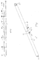
- a safety barrier guardrail system 1 comprising a series of spaced vacuum anchor devices 2, each arranged to support a respective upright post 3. Adjustable length guardrail cross-members 4 interconnect the upright posts 3.
- the safety barrier guardrail system 1 is particularly suited for use on uneven or undulating surfaces for personnel working at height, such as for example working on the wing of an aircraft for maintenance purposes. For this reason the s as shown in figure 1 is shaped to define an aircraft wing shaped pen boundary. End vacuum anchors 2a 2b anchor on to the fuselage of the aircraft.
- the vacuum anchor devices secured to the aircraft wing and fuselage are connected via vacuum lines 7.
- the vacuum anchor devices are generally in accordance with those known in the art and accordingly will not be described in detail herein.
- the vacuum anchor devices 2 have vacuum line connectors 5, 6 for connection to a vacuum line 7.
- the vacuum anchor device 2 has a main body 2a which supports a rubber flexible sucker member 2b.
- the vacuum is typically applied from a remote vacuum source.
- Appropriate check valves and control vales are typically mounted to the anchor body 2a.
- the pair of vacuum line connectors 5,6 enable the series of spaced vacuum anchors to be connected in series in the vacuum circuit such that vacuum can be applied to all the vacuum anchor devices from a single vacuum generation unit 8.
- Each vacuum anchor device has a central cylindrical socket for receiving one of the upright posts. This is known in the art and shown in figure 4 of US6607054 where the socket is described as 'hole 16'.
- the post 3 is not mounted to be directly received within the cylindrical socket of the vacuum anchor device 2, but rather an intermediate mounting device 9 is used to secure the post 3 with respect to the vacuum anchor device.
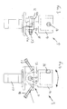
- the mounting device 9 for the posts of the safety barrier guardrail system 1 comprises a cylindrical stem portion 10, extending downwardly from an angularly adjustable articulated mounting joint 11.
- the angularly adjustable articulated mounting joint 11 comprises a mounting body 12 defining a recess spanned by a bolt 13 extending between spaced uprights 12b, 12c.
- the bolt 13 provides a rotatable, pivot or hinge mounting for the post and in the embodiment shown mounts a receiving socket 14 which receives the lower end of the upright support post 3.
- a fixing flange 15 extends from the underside of the socket 12 and is provided with a mounting aperture through which the bolt 13 may pass.
- the socket 14 may be dispensed with and the support post 3 may be directly mounted to the angularly adjustable mounting at the hinge bolt 13, by means of providing a special adaptation to the lower end of the support post 3, in order to provide a mounting flange and aperture similar to that provided for the socket 14. It is however generally preferred that the socket mounting 14 is used in order to enable standard existing mounting posts to be accommodated.
- the socket mounting is provided with a set screw 16 threaded into a threaded through bore in the side of the socket 14 in order to enable the support post 3 to be securely held when received in the socket 14.
- the angularly adjustable articulated mounting joint 11 for the support post 2 enables the support post 2 to be angularly adjusted to provide varying degrees of angular inclination with respect to the surface to which the vacuum anchor device is secured. This is achieved by the axis of the hinge or pivot bolt being transverse to the longitudinal axis of the upright support post. Additionally positional flexibility is achieved by means of the stem 10 being rotatable about its longitudinal axis whilst received in the socket of the vacuum anchor device 2.
- articulated joints may be employed to give the desired range of movement, such as for exampled a gimballed mount or joint or a ball and socket joint.
- the angularly adjustable articulated mounting is further provided with a securing arrangement for securing the mounting in the selected configuration in which the support post 3 is orientated set with its longitudinal axis directed in the desired direction.
- a securing arrangement for securing the mounting in the selected configuration in which the support post 3 is orientated set with its longitudinal axis directed in the desired direction.
- this is achieved by means of opposed directed threaded securing members 17, 18 directed through the mounting body 12 and secured in threaded bores.
- the ends of the threaded securing members 17, 18 can be advanced into the recess in the mounting body 12 to contact the fixing flange 15.
- the ends of the threaded securing members 17, 18 are both abutting tight against the opposed sides of the fixing flange 15, the mounting is secured in the selected configuration in which the support post is orientated set with its longitudinal axis extending in the desired direction.
- the heads of the threaded securing members are readily accessible in order to be actuated to effect tightening against the fixing flange.
- the threaded securing members are typically bolts.
- Other mechanical fixings can be used to secure the mounting at the correct attitude, with the support post in the desired orientation.
- the bolts 17, 18 are angled inclined upwardly such that the ends of the bolts contact the opposed sides of the mounting flange 15 at a level above the level of the hinge bolt axis 13. This enhances the security with which the socket 14 and post 3 is held in position.
- the cross-members 4 of the safety barrier guardrail system 1 are adjustable in length and comprise an inner tube 4a mounted telescopically within respective opposed end tubes 4b and 4c. Respective securing pins 21 are tethered to the tubes 4b and 4c by tethers 22 and pas through receiving apertures in the respective tubes 4b and 4c to engage with selected ones of a series of spaced apertures provided in the inner tube 4a, dependent upon the length selected for the respective overall cross member tube 4.
- the ends of the cross-member tube 4 are provided with apertured flanges 25 enabling the tubes to be bolted to respective collars 27 which are secured about the support posts 3.
- the collars 27 are positionally movable along the length of the support posts 3 and securable at desired selected positions by means of tightenable collar bolts (not shown) as known in the general art.
- the safety barrier guardrail system 1 of the invention provides a reliable system having a set number of component parts that can be quickly and conveniently set up to provide a safe barrier or guardrail system. Because the mounting is articulated to enable the orientation angle of the support post to be adjusted with respect to the anchor device, the support posts can be orientated 'true' upright even when adjacent support pots are mounted on uneven or differently inclined mounting surfaces.
Landscapes
- Health & Medical Sciences (AREA)
- General Health & Medical Sciences (AREA)
- Business, Economics & Management (AREA)
- Emergency Management (AREA)
- Refuge Islands, Traffic Blockers, Or Guard Fence (AREA)
Priority Applications (1)
| Application Number | Priority Date | Filing Date | Title |
|---|---|---|---|
| EP10171902.9A EP2415501B1 (fr) | 2010-08-04 | 2010-08-04 | Système de barrière de sécurité |
Applications Claiming Priority (1)
| Application Number | Priority Date | Filing Date | Title |
|---|---|---|---|
| EP10171902.9A EP2415501B1 (fr) | 2010-08-04 | 2010-08-04 | Système de barrière de sécurité |
Publications (2)
| Publication Number | Publication Date |
|---|---|
| EP2415501A1 true EP2415501A1 (fr) | 2012-02-08 |
| EP2415501B1 EP2415501B1 (fr) | 2018-09-19 |
Family
ID=43332845
Family Applications (1)
| Application Number | Title | Priority Date | Filing Date |
|---|---|---|---|
| EP10171902.9A Active EP2415501B1 (fr) | 2010-08-04 | 2010-08-04 | Système de barrière de sécurité |
Country Status (1)
| Country | Link |
|---|---|
| EP (1) | EP2415501B1 (fr) |
Citations (4)
| Publication number | Priority date | Publication date | Assignee | Title |
|---|---|---|---|---|
| US5676085A (en) * | 1996-07-08 | 1997-10-14 | Northern Pacific Development Corp. | Vacuum operated boat mooring device |
| US6607054B1 (en) | 1998-10-31 | 2003-08-19 | Rota Limited | Safety device |
| EP1632271A1 (fr) * | 2004-09-03 | 2006-03-08 | Fallprotec S.A. | Ancre intermediaire pour ligne de vie |
| GB2435485A (en) * | 2006-02-22 | 2007-08-29 | Livis Ltd | Barrier attached to surface via suction feet with central vacuum source |
Family Cites Families (1)
| Publication number | Priority date | Publication date | Assignee | Title |
|---|---|---|---|---|
| FR2761096B1 (fr) * | 1997-03-24 | 2000-10-13 | Francis Lille | Organes de maintien d'une grille de securite pour chantier, principalement pour charpentiers ou couvreurs |
-
2010
- 2010-08-04 EP EP10171902.9A patent/EP2415501B1/fr active Active
Patent Citations (4)
| Publication number | Priority date | Publication date | Assignee | Title |
|---|---|---|---|---|
| US5676085A (en) * | 1996-07-08 | 1997-10-14 | Northern Pacific Development Corp. | Vacuum operated boat mooring device |
| US6607054B1 (en) | 1998-10-31 | 2003-08-19 | Rota Limited | Safety device |
| EP1632271A1 (fr) * | 2004-09-03 | 2006-03-08 | Fallprotec S.A. | Ancre intermediaire pour ligne de vie |
| GB2435485A (en) * | 2006-02-22 | 2007-08-29 | Livis Ltd | Barrier attached to surface via suction feet with central vacuum source |
Also Published As
| Publication number | Publication date |
|---|---|
| EP2415501B1 (fr) | 2018-09-19 |
Similar Documents
| Publication | Publication Date | Title |
|---|---|---|
| US20120031702A1 (en) | Mounting for a Safety System | |
| US11149465B2 (en) | Horizontal cable rail barrier | |
| AU2006269521B2 (en) | Releasable post-cable connection for a cable barrier system | |
| US8025125B2 (en) | Anchor assembly | |
| US7568679B2 (en) | Cable barrier system | |
| US20190226165A1 (en) | Bridge overhang bracket assembly with adjustable side member | |
| US7798741B2 (en) | Cable-release anchor assembly | |
| US10370857B2 (en) | Adjustable railing | |
| WO2010072525A2 (fr) | Dispositifs de sécurité | |
| HK1252455A1 (zh) | 支架 | |
| KR200472886Y1 (ko) | 펜스 지주각도 조절장치 | |
| EP2415501B1 (fr) | Système de barrière de sécurité | |
| KR20150010510A (ko) | 울타리용 연결 장치 | |
| US20200129789A1 (en) | Fall protection safety apparatus | |
| US11649637B2 (en) | Handrail for scaffolding structures | |
| KR101299082B1 (ko) | 각도조절형 펜스 | |
| ES2464518T3 (es) | Soporte de pasamanos protectores | |
| CN101267861B (zh) | 中间托架 | |
| US20240353055A1 (en) | Gain Base for Power Distribution Systems | |
| JP5824303B2 (ja) | 防護柵 | |
| AU2017100135B4 (en) | A roof safety anchor | |
| AU2016219739A1 (en) | Edge Protection Components, Assembly and Process | |
| CN218622046U (zh) | 一种喷射角度可调的洒水车用中喷推安装结构 |
Legal Events
| Date | Code | Title | Description |
|---|---|---|---|
| AK | Designated contracting states |
Kind code of ref document: A1 Designated state(s): AL AT BE BG CH CY CZ DE DK EE ES FI FR GB GR HR HU IE IS IT LI LT LU LV MC MK MT NL NO PL PT RO SE SI SK SM TR |
|
| AX | Request for extension of the european patent |
Extension state: BA ME RS |
|
| PUAI | Public reference made under article 153(3) epc to a published international application that has entered the european phase |
Free format text: ORIGINAL CODE: 0009012 |
|
| 17P | Request for examination filed |
Effective date: 20120808 |
|
| STAA | Information on the status of an ep patent application or granted ep patent |
Free format text: STATUS: EXAMINATION IS IN PROGRESS |
|
| 17Q | First examination report despatched |
Effective date: 20170516 |
|
| GRAP | Despatch of communication of intention to grant a patent |
Free format text: ORIGINAL CODE: EPIDOSNIGR1 |
|
| STAA | Information on the status of an ep patent application or granted ep patent |
Free format text: STATUS: GRANT OF PATENT IS INTENDED |
|
| INTG | Intention to grant announced |
Effective date: 20180425 |
|
| GRAS | Grant fee paid |
Free format text: ORIGINAL CODE: EPIDOSNIGR3 |
|
| GRAA | (expected) grant |
Free format text: ORIGINAL CODE: 0009210 |
|
| STAA | Information on the status of an ep patent application or granted ep patent |
Free format text: STATUS: THE PATENT HAS BEEN GRANTED |
|
| AK | Designated contracting states |
Kind code of ref document: B1 Designated state(s): AL AT BE BG CH CY CZ DE DK EE ES FI FR GB GR HR HU IE IS IT LI LT LU LV MC MK MT NL NO PL PT RO SE SI SK SM TR |
|
| REG | Reference to a national code |
Ref country code: GB Ref legal event code: FG4D |
|
| REG | Reference to a national code |
Ref country code: CH Ref legal event code: EP |
|
| REG | Reference to a national code |
Ref country code: DE Ref legal event code: R096 Ref document number: 602010053657 Country of ref document: DE |
|
| REG | Reference to a national code |
Ref country code: AT Ref legal event code: REF Ref document number: 1042553 Country of ref document: AT Kind code of ref document: T Effective date: 20181015 |
|
| REG | Reference to a national code |
Ref country code: IE Ref legal event code: FG4D |
|
| REG | Reference to a national code |
Ref country code: NL Ref legal event code: FP |
|
| PG25 | Lapsed in a contracting state [announced via postgrant information from national office to epo] |
Ref country code: NO Free format text: LAPSE BECAUSE OF FAILURE TO SUBMIT A TRANSLATION OF THE DESCRIPTION OR TO PAY THE FEE WITHIN THE PRESCRIBED TIME-LIMIT Effective date: 20181219 Ref country code: SE Free format text: LAPSE BECAUSE OF FAILURE TO SUBMIT A TRANSLATION OF THE DESCRIPTION OR TO PAY THE FEE WITHIN THE PRESCRIBED TIME-LIMIT Effective date: 20180919 Ref country code: BG Free format text: LAPSE BECAUSE OF FAILURE TO SUBMIT A TRANSLATION OF THE DESCRIPTION OR TO PAY THE FEE WITHIN THE PRESCRIBED TIME-LIMIT Effective date: 20181219 Ref country code: FI Free format text: LAPSE BECAUSE OF FAILURE TO SUBMIT A TRANSLATION OF THE DESCRIPTION OR TO PAY THE FEE WITHIN THE PRESCRIBED TIME-LIMIT Effective date: 20180919 Ref country code: GR Free format text: LAPSE BECAUSE OF FAILURE TO SUBMIT A TRANSLATION OF THE DESCRIPTION OR TO PAY THE FEE WITHIN THE PRESCRIBED TIME-LIMIT Effective date: 20181220 Ref country code: LT Free format text: LAPSE BECAUSE OF FAILURE TO SUBMIT A TRANSLATION OF THE DESCRIPTION OR TO PAY THE FEE WITHIN THE PRESCRIBED TIME-LIMIT Effective date: 20180919 |
|
| REG | Reference to a national code |
Ref country code: LT Ref legal event code: MG4D |
|
| PG25 | Lapsed in a contracting state [announced via postgrant information from national office to epo] |
Ref country code: AL Free format text: LAPSE BECAUSE OF FAILURE TO SUBMIT A TRANSLATION OF THE DESCRIPTION OR TO PAY THE FEE WITHIN THE PRESCRIBED TIME-LIMIT Effective date: 20180919 Ref country code: LV Free format text: LAPSE BECAUSE OF FAILURE TO SUBMIT A TRANSLATION OF THE DESCRIPTION OR TO PAY THE FEE WITHIN THE PRESCRIBED TIME-LIMIT Effective date: 20180919 Ref country code: HR Free format text: LAPSE BECAUSE OF FAILURE TO SUBMIT A TRANSLATION OF THE DESCRIPTION OR TO PAY THE FEE WITHIN THE PRESCRIBED TIME-LIMIT Effective date: 20180919 |
|
| REG | Reference to a national code |
Ref country code: AT Ref legal event code: MK05 Ref document number: 1042553 Country of ref document: AT Kind code of ref document: T Effective date: 20180919 |
|
| PG25 | Lapsed in a contracting state [announced via postgrant information from national office to epo] |
Ref country code: EE Free format text: LAPSE BECAUSE OF FAILURE TO SUBMIT A TRANSLATION OF THE DESCRIPTION OR TO PAY THE FEE WITHIN THE PRESCRIBED TIME-LIMIT Effective date: 20180919 Ref country code: PL Free format text: LAPSE BECAUSE OF FAILURE TO SUBMIT A TRANSLATION OF THE DESCRIPTION OR TO PAY THE FEE WITHIN THE PRESCRIBED TIME-LIMIT Effective date: 20180919 Ref country code: IT Free format text: LAPSE BECAUSE OF FAILURE TO SUBMIT A TRANSLATION OF THE DESCRIPTION OR TO PAY THE FEE WITHIN THE PRESCRIBED TIME-LIMIT Effective date: 20180919 Ref country code: RO Free format text: LAPSE BECAUSE OF FAILURE TO SUBMIT A TRANSLATION OF THE DESCRIPTION OR TO PAY THE FEE WITHIN THE PRESCRIBED TIME-LIMIT Effective date: 20180919 Ref country code: AT Free format text: LAPSE BECAUSE OF FAILURE TO SUBMIT A TRANSLATION OF THE DESCRIPTION OR TO PAY THE FEE WITHIN THE PRESCRIBED TIME-LIMIT Effective date: 20180919 Ref country code: CZ Free format text: LAPSE BECAUSE OF FAILURE TO SUBMIT A TRANSLATION OF THE DESCRIPTION OR TO PAY THE FEE WITHIN THE PRESCRIBED TIME-LIMIT Effective date: 20180919 Ref country code: ES Free format text: LAPSE BECAUSE OF FAILURE TO SUBMIT A TRANSLATION OF THE DESCRIPTION OR TO PAY THE FEE WITHIN THE PRESCRIBED TIME-LIMIT Effective date: 20180919 Ref country code: IS Free format text: LAPSE BECAUSE OF FAILURE TO SUBMIT A TRANSLATION OF THE DESCRIPTION OR TO PAY THE FEE WITHIN THE PRESCRIBED TIME-LIMIT Effective date: 20190119 |
|
| PG25 | Lapsed in a contracting state [announced via postgrant information from national office to epo] |
Ref country code: SK Free format text: LAPSE BECAUSE OF FAILURE TO SUBMIT A TRANSLATION OF THE DESCRIPTION OR TO PAY THE FEE WITHIN THE PRESCRIBED TIME-LIMIT Effective date: 20180919 Ref country code: PT Free format text: LAPSE BECAUSE OF FAILURE TO SUBMIT A TRANSLATION OF THE DESCRIPTION OR TO PAY THE FEE WITHIN THE PRESCRIBED TIME-LIMIT Effective date: 20190119 Ref country code: SM Free format text: LAPSE BECAUSE OF FAILURE TO SUBMIT A TRANSLATION OF THE DESCRIPTION OR TO PAY THE FEE WITHIN THE PRESCRIBED TIME-LIMIT Effective date: 20180919 |
|
| REG | Reference to a national code |
Ref country code: DE Ref legal event code: R097 Ref document number: 602010053657 Country of ref document: DE |
|
| PLBE | No opposition filed within time limit |
Free format text: ORIGINAL CODE: 0009261 |
|
| STAA | Information on the status of an ep patent application or granted ep patent |
Free format text: STATUS: NO OPPOSITION FILED WITHIN TIME LIMIT |
|
| PG25 | Lapsed in a contracting state [announced via postgrant information from national office to epo] |
Ref country code: DK Free format text: LAPSE BECAUSE OF FAILURE TO SUBMIT A TRANSLATION OF THE DESCRIPTION OR TO PAY THE FEE WITHIN THE PRESCRIBED TIME-LIMIT Effective date: 20180919 |
|
| 26N | No opposition filed |
Effective date: 20190620 |
|
| PG25 | Lapsed in a contracting state [announced via postgrant information from national office to epo] |
Ref country code: SI Free format text: LAPSE BECAUSE OF FAILURE TO SUBMIT A TRANSLATION OF THE DESCRIPTION OR TO PAY THE FEE WITHIN THE PRESCRIBED TIME-LIMIT Effective date: 20180919 |
|
| PG25 | Lapsed in a contracting state [announced via postgrant information from national office to epo] |
Ref country code: TR Free format text: LAPSE BECAUSE OF FAILURE TO SUBMIT A TRANSLATION OF THE DESCRIPTION OR TO PAY THE FEE WITHIN THE PRESCRIBED TIME-LIMIT Effective date: 20180919 |
|
| PG25 | Lapsed in a contracting state [announced via postgrant information from national office to epo] |
Ref country code: LI Free format text: LAPSE BECAUSE OF NON-PAYMENT OF DUE FEES Effective date: 20190831 Ref country code: MC Free format text: LAPSE BECAUSE OF FAILURE TO SUBMIT A TRANSLATION OF THE DESCRIPTION OR TO PAY THE FEE WITHIN THE PRESCRIBED TIME-LIMIT Effective date: 20180919 Ref country code: CH Free format text: LAPSE BECAUSE OF NON-PAYMENT OF DUE FEES Effective date: 20190831 Ref country code: LU Free format text: LAPSE BECAUSE OF NON-PAYMENT OF DUE FEES Effective date: 20190804 |
|
| PG25 | Lapsed in a contracting state [announced via postgrant information from national office to epo] |
Ref country code: IE Free format text: LAPSE BECAUSE OF NON-PAYMENT OF DUE FEES Effective date: 20190804 |
|
| PG25 | Lapsed in a contracting state [announced via postgrant information from national office to epo] |
Ref country code: CY Free format text: LAPSE BECAUSE OF FAILURE TO SUBMIT A TRANSLATION OF THE DESCRIPTION OR TO PAY THE FEE WITHIN THE PRESCRIBED TIME-LIMIT Effective date: 20180919 |
|
| PG25 | Lapsed in a contracting state [announced via postgrant information from national office to epo] |
Ref country code: HU Free format text: LAPSE BECAUSE OF FAILURE TO SUBMIT A TRANSLATION OF THE DESCRIPTION OR TO PAY THE FEE WITHIN THE PRESCRIBED TIME-LIMIT; INVALID AB INITIO Effective date: 20100804 Ref country code: MT Free format text: LAPSE BECAUSE OF FAILURE TO SUBMIT A TRANSLATION OF THE DESCRIPTION OR TO PAY THE FEE WITHIN THE PRESCRIBED TIME-LIMIT Effective date: 20180919 |
|
| PG25 | Lapsed in a contracting state [announced via postgrant information from national office to epo] |
Ref country code: MK Free format text: LAPSE BECAUSE OF FAILURE TO SUBMIT A TRANSLATION OF THE DESCRIPTION OR TO PAY THE FEE WITHIN THE PRESCRIBED TIME-LIMIT Effective date: 20180919 |
|
| REG | Reference to a national code |
Ref country code: DE Ref legal event code: R082 Ref document number: 602010053657 Country of ref document: DE Representative=s name: JONES DAY RECHTSANWAELTE PATENTANWAELTE, DE |
|
| P01 | Opt-out of the competence of the unified patent court (upc) registered |
Effective date: 20230626 |
|
| PGFP | Annual fee paid to national office [announced via postgrant information from national office to epo] |
Ref country code: GB Payment date: 20250612 Year of fee payment: 16 |
|
| PGFP | Annual fee paid to national office [announced via postgrant information from national office to epo] |
Ref country code: NL Payment date: 20250613 Year of fee payment: 16 |
|
| PGFP | Annual fee paid to national office [announced via postgrant information from national office to epo] |
Ref country code: FR Payment date: 20250610 Year of fee payment: 16 |
|
| PGFP | Annual fee paid to national office [announced via postgrant information from national office to epo] |
Ref country code: DE Payment date: 20250611 Year of fee payment: 16 |
|
| PGFP | Annual fee paid to national office [announced via postgrant information from national office to epo] |
Ref country code: BE Payment date: 20250703 Year of fee payment: 16 |