EP2415525A2 - Pipette pour un système de pipetage avec pipette et seringue - Google Patents
Pipette pour un système de pipetage avec pipette et seringue Download PDFInfo
- Publication number
- EP2415525A2 EP2415525A2 EP11006264A EP11006264A EP2415525A2 EP 2415525 A2 EP2415525 A2 EP 2415525A2 EP 11006264 A EP11006264 A EP 11006264A EP 11006264 A EP11006264 A EP 11006264A EP 2415525 A2 EP2415525 A2 EP 2415525A2
- Authority
- EP
- European Patent Office
- Prior art keywords
- pipette
- toothing
- rack
- syringe
- piston
- Prior art date
- Legal status (The legal status is an assumption and is not a legal conclusion. Google has not performed a legal analysis and makes no representation as to the accuracy of the status listed.)
- Granted
Links
Images

Classifications
-
- B—PERFORMING OPERATIONS; TRANSPORTING
- B01—PHYSICAL OR CHEMICAL PROCESSES OR APPARATUS IN GENERAL
- B01L—CHEMICAL OR PHYSICAL LABORATORY APPARATUS FOR GENERAL USE
- B01L3/00—Containers or dishes for laboratory use, e.g. laboratory glassware; Droppers
- B01L3/02—Burettes; Pipettes
- B01L3/021—Pipettes, i.e. with only one conduit for withdrawing and redistributing liquids
- B01L3/0217—Pipettes, i.e. with only one conduit for withdrawing and redistributing liquids of the plunger pump type
- B01L3/0234—Repeating pipettes, i.e. for dispensing multiple doses from a single charge
-
- B—PERFORMING OPERATIONS; TRANSPORTING
- B01—PHYSICAL OR CHEMICAL PROCESSES OR APPARATUS IN GENERAL
- B01L—CHEMICAL OR PHYSICAL LABORATORY APPARATUS FOR GENERAL USE
- B01L2200/00—Solutions for specific problems relating to chemical or physical laboratory apparatus
- B01L2200/12—Specific details about manufacturing devices
-
- B—PERFORMING OPERATIONS; TRANSPORTING
- B01—PHYSICAL OR CHEMICAL PROCESSES OR APPARATUS IN GENERAL
- B01L—CHEMICAL OR PHYSICAL LABORATORY APPARATUS FOR GENERAL USE
- B01L2300/00—Additional constructional details
- B01L2300/12—Specific details about materials
Definitions
- the invention relates to a pipette for a pipette system with pipette and syringe, namely a pipette having the features of the preamble of claim 1.
- Pipettes are devices for measuring and transferring liquids.
- the present is a pipette that allows a gradual release of a liquid from a syringe (Repetierpipette).
- a pipette is for example from the DE 199 63 141 A1
- liquid is taken up in the syringe inserted in the pipette housing of the pipette in one go.
- the pipette is then moved to the place of use.
- the liquid taken up in the syringe is released again step by step by repeated actuation of the actuating lever located on the pipette housing in previously set portions.
- the repeating pipette known from practice has a piston adjusting device in the form of a rack-pawl combination, the rack is in one piece of extremely dimensionally stable metal , in particular brass, machined.
- the cost of producing such a rack is relatively high in relation to the cost of the pipette as part of a large-scale production.
- the teaching of the present invention is based on a pipette with a one-piece rack in such a piston adjusting device. From the EP 0 143 796 B1 Although it is a two-piece rack out, but on each section has a different teeth with different tasks, On a rack part teeth in sawtooth shape is integrally formed. It can be assumed that this is also a metal rack. whose teeth have been produced by machining on the actual rack carcass.
- the teaching is based on the problem to optimize the known pipette with axially displaceable rack while maintaining the precision in terms of manufacturing costs in particular under aspects of mass production.
- the rack is now made in several parts, namely at least two parts, preferably exactly two parts. It consists first of a carrier which has a receptacle for a toothing part. In or on the receptacle of the carrier sits the toothing part, which in turn has the toothing of the rack.
- the carrier on the one hand and the toothing part on the other hand can be made of different materials.
- the material of the carrier can be adapted to the local requirements.
- the carrier must be dimensionally stable and fix the toothing part safely and correctly in the piston adjusting device. He does not have to be particularly well-suited and he does not have to meet the special requirements of a finely-illustrated gearing.
- the toothing part is highly dimensionally accurate to manufacture and must be highly precise executable especially in the teeth. This is usually a more expensive material to use.
- the outer shape of the toothing part, in particular what deflections or the like. does not have to be particularly precise, because here the carrier acts with its rigidity, the toothing part can be made in particular relatively thin. Its spatial orientation and fixation is experienced only in connection with the serving as a stiff backbone wearer,
- the toothing part consists of a high-quality, preferably fiber-reinforced plastic, in particular of a fiber-reinforced PEEK.
- a plastic part can be manufactured as a series part with high precision and excellent dimensional stability and low shrinkage.
- this toothing part is expediently made as small as possible in terms of volume, because the material used is relatively expensive.
- the wearer can be quite voluminous and is designed so that it is as stiff as possible. It is less important for its dimensional accuracy in detail.
- the material to be used here can be significantly cheaper than the material of the toothing part.
- Each of the two parts are assigned the tasks that best suit them.
- the toothing part has a longitudinal contour, which is adapted to a longitudinal counter contour on the carrier so that a positive, preferably axially straight guide results, wherein , Preferably, the contour and the mating contour are formed as a T-slot guide. By this guide, the flat and usually relatively thin toothing part is aligned.
- the dimensional accuracy of the toothing part can be further improved by the fact that the toothed part seen in cross section has at least one longitudinal stiffening web on the side opposite the toothing.
- the filling behavior in the injection molding process in a plastic part is significantly smoother by such a bridge.
- the toothing part including the toothing in cross section has a ratio of the width to the height greater than 1.5, preferably greater than 4.0. Over its length, such a relatively uniformly elongate toothing part hardly has a delay and only a relatively small deflection. Due to the low height in relation to the width, it can be aligned relatively easily when inserted into the carrier.
- the toothing part can thus be optimized for the dimensional accuracy of the tooth pitch of the toothing, the deflection over the entire length of the toothing part may have less importance.
- the teaching of the invention is of particular importance with a relatively small tooth pitch, tooth pitches below 1 mm can be produced in metal racks only with great effort.
- a high-quality plastic injection molding technique can be according to the teachings of the invention, smaller tooth pitches to reach. Accordingly, it is recommended according to preferred teaching that the toothing has a pitch of less than 1.0 mm, preferably less than 0.6 mm. It is obvious that a smaller pitch allows a greater number of steps and possible sub-volumes.
- the toothing in the case of the pipette according to the invention can also be optimized in the tooth form and in the tooth height. It is recommended that the toothing is sawtooth-shaped and the tooth angle between the tooth back and the tooth flank is between 25 ° and 45 °.
- the teeth are very fine on both the gearing and the pawl.
- the pawl which preferably consists of fiber-reinforced plastic, having a plurality of ratchet teeth, preferably three ratchet teeth.
- the width of the pawl is greater than 4 mm, preferably greater than 5.5 mm.
- the ratchet teeth of the pawl have the sawtooth shape of the toothing and that, preferably, the pitch of the ratchet teeth is less than the pitch of the toothing.
- the ratchet teeth so fall even with appropriate inclination of the pawl in the teeth on the toothing part and achieve a safe, force-transmitting engagement
- the pipette housing which limits the movement of the pawl in the direction of the syringe.
- a rigidly arranged stop is present on the pipette housing, which limits the movement of the pawl in the direction of the syringe.
- Such a construction is also recommended in the case of the pipette according to the invention.
- the toothing part has a stroke stop for the absorption of liquid in the syringe. The stroke stop ensures dimensional accuracy when engaging the first stroke to dispense liquid after previously taking up liquid in the syringe.
- the rack has a cam which cooperates with the spool and with the piston advanced into the syringe raises the spool so that the pawl is dug out of the gearing.
- the cam is mounted on the rack in the axial direction adjustable.
- the cam is mounted in an adjustable manner in the axial direction on a sliding block arranged on the carrier of the rack. It is particularly useful in this case then that the carrier of the rack is designed in one piece with this sliding guide.
- the piston adjusting device typically has a receptacle for a piston head of a syringe. It is particularly useful then that the carrier of the rack is made in one piece with this recording
- the carrier of the toothed rack at the lower end is made in one piece with the receptacle of the piston adjusting device and integrally formed at the upper end in one piece with the sliding guide for the cam.
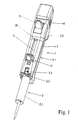
- Fig. 1 shows the basic design of a pipette 1 according to the invention with an inserted syringe 2.
- the syringe 2 has a cylinder 2.1 with a mounting portion 2.2, which is preferably designed as a flange, and with a piston which in Fig. 1 can not be seen because it is located in the pipette housing 3 of the pipette 1 shown there.
- the piston has a piston which is also pushed completely out of the cylinder 2.1 and out of this cylinder 2.1 on the end of the piston head 2.3.
- the pipette housing 3 defines a longitudinal axis which is coaxial with the rotationally symmetrical syringe (2).
- Fig. 1 is indicated that in the pipette housing 3 in the direction of the longitudinal axis of the pipette housing 3, that is, axially displaceable piston adjusting device 4 for the piston head 2.3 of the syringe 2 is located.
- the piston adjusting device 4 is actuated by means of a movable in the pipette housing 3 and partially protruding from the pipette housing 3 for the purpose of manual operation operating lever 5.
- a handle part 3.1 and a finger strap 3.2 are formed on the pipette housing 3. If you hold the pipette housing 3 on the handle part 3.1 with the palm, so you can press the operating lever 5 with your thumb, ie in Fig. 1 Press down towards the syringe (2).
- Each actuation of the operating lever 5 has the delivery of a specific, precisely set amount of the previously recorded in the syringe 2 liquid (repetitive pipette).
- a volume setting device 6 is provided on the pipette housing 3. This adjustment is known per se from the prior art and is realized in a similar manner also in the case of the pipette forming the starting point.
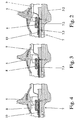
- the piston adjusting device 4 initially has a toothed rod 7 which is axially displaceably arranged in the pipette housing 3 and is coupled to the piston head 2, 3 of an inserted syringe 2, which toothing 7. 8 and 9 Is provided on the operating lever 5 is a pivotally mounted pawl 8 of the piston adjusting device 4, which engages upon actuation of the actuating lever 5 in the opposing toothing 7,1 of the rack 7, as can be seen from the episode of Fig. 2 to 4 good to take. If one actuates the actuating lever 5, the piston of the syringe 2 is displaced by this engagement via the piston head 2.3, regularly downwards into the cylinder 2.1, for the purpose of dispensing a certain set amount of liquid.
- FIGS. 2 and 3 On the rack 7 is a spool 9, the in FIGS. 2 and 3 is particularly clear. He is executed here as a double-folded bent part.
- This control slide 9 holds the pawl when the actuating lever 5 is not actuated (FIG. Fig. 2 ) About the teeth 7.1 of the rack 7.
- This spool 9 is adjustable in its position on the rack 7, what it just the volume setting 6 there.
- Other embodiments of the spool 9 are known, the gruindslegihich control the engagement of the pawl 8 in the toothing 7. If the operating lever 5 is actuated, it moves from the in Fig. 2 shown position to the left.
- the rack 7 is made of several parts and at least a support 7.2 and a toothing part 7.3, wherein the carrier has a receptacle 7.2 7.2 for the toothing part 7.3 and the Verzabnungsteil 7.3 Teeth 7.1 carries.
- the carrier 7.2 on the one hand and the toothing part 7.3.
- they are made of different materials, which can meet the respective requirements particularly well. This has the advantages already explained in detail in the general part of the description.
- the rack 7 may be made in two parts, but in principle may include more parts to the rack 7, essential is the special task assignment to the carrier 7.2 on the one hand and to the physically separate from the carrier, but connected to him gearing part 7.3, the teeth. 7 on the other hand. According to the invention therefore no one-piece design of the rack 7 is provided, but a multi-part design.
- the toothing part 7, 3 consists of a high-strength material, which can be manufactured dimensionally accurate and with minimal shrinkage, and that the carrier 7.2 consists of a material that is more cost-effective compared to the material of the toothing part 7.3, which less good dimensionally accurate to manufacture.
- the toothing part 7.3 is made of a high quality, preferably fiber reinforced plastic, in particular of a fiber reinforced PEEK, consists.
- the carrier 7, 2 consists of steel, in particular stainless steel, or of a dimensionally stable plastic, preferably of PPS
- the toothing part 7.3 has a longitudinal contour 7.4, which is adapted to a longitudinally extending counter contour 7.5 on the carrier 7.2 in such a way that a form-fitting, axially straight guide results.
- the contour 7.4 and the mating contour 7.5 are formed as a T-slot guide.
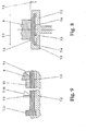
- the T-slot guide can be in Fig. 8 recognize very well.
- the toothing part 7.3 in cross-section at least one longitudinal stiffening web 7.6 relative to the toothing 7.1. More precisely, there are four equally spaced stiffening webs 7, 6.
- Fig. 8 can be the profiling of the toothing part 7.3 remove.
- the toothing part 7.3 including the toothing 7.1 in cross section has a ratio of the width 7.7 to the height 7.8 including the toothing 7.1 greater than 1.5, preferably greater than 4.0.
- a ratio of the width of 7.7 to the height of 7.8, which is measured to the top of the teeth 7.1 results in a little more than 4.
- the outer contour of the toothing part 7.3 is basically rectangular although executed with a two-sided stage of the T-slot guide.
- the illustrated and preferred embodiment shows for the teeth 7.1 a very fine pitch, in particular one of less than 1 mm, preferably less than 0.6 mm. This one looks especially good in Fig. 9 , It recognizes one that the teeth 7.1 is designed sawtooth-shaped and the tooth angle 7.10 between the tooth back and the tooth flank is between 25 ° and 45 °. One can see here, despite the fineness of the division 7.9 sufficient tooth height, which allows a safe engagement of the ratchet teeth of the pawl 8,
- the pawl 8 which preferably consists of fiber-reinforced plastic, has a plurality of ratchet teeth, preferably three ratchet teeth.
- the three ratchet teeth ensure a secure engagement of the pawl 8 in the fine toothing 7.1.
- the ratchet teeth of the pawl 8 have the sawtooth shape of the teeth 7.1 and the pitch of the ratchet teeth is less than the pitch of the teeth 7.1.
- Fig. 8 illustrated and so far preferred embodiment shows a construction in which the width of the pawl 8 is greater than 4 mm, preferably greater than 5.5 mm, is.
- the width of the pawl 8 also depends on the lifting force to be transmitted, which then has to be introduced over the width into the toothing part 7.3 and thus into the rack 7 with a particularly fine pitch of the toothing 7.1.
- the total support 7.2 has a total width, which is about 1.5 times to 2 times the Width of the pawl 8 is.
- a fixedly positioned stop 10 is provided which limits the movement of the pawl 8 in the direction of the syringe 2. This has the meaning explained in the general part of the description.
- the stop 10 may be assigned to the actuating lever 5 instead of the pawl 8 also directly. It is fixedly attached to the pipette housing 3. You can see in Fig. 9 the pawl 8 are immediately in front of the stop 10.
- the rack 7 has a cam 7.12, which cooperates with the spool 9 and raised in the syringe 2 advanced piston the spool 9, so that the pawl 8 is dug out of the "teeth 7.1.
- the stop given by the cam 7.12 can be seen in Fig. 5 to 7 in different variants.
- the cam 7.12 is integrally formed on the carrier 7.2.
- the cam 7.12 acts so that the spool 9 is raised and with the pawl 8 lifts up and triggers their ratchet teeth from the gearing 7.1 on the gearing part 7.3.
- the pawl 8 then moves at idle It has, in order to allow this, even a raised contact surface 8.1, with which it rests on the spool 9.
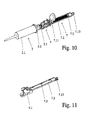
- Fig. 10 is that assembly of the pipette 1 is shown, which is driven with the exception of the cylinder 2.1 of the syringe 2 during the actuating stroke.
- the piston adjusting device 4 may for example be constructed as in the DE 20 2010 009 747 U1 disclosed. It has at least one coupling for the piston head 2.3 and a button for its operation. This can also be used to move the piston with the piston head 2.3 in the syringe 2 and the rack 7 in the pipette housing 3.
- Fig. 11 shows, here has the coupling of the piston adjusting device 4 a receptacle 4.1, which is connected directly or indirectly with the piston head 2.3 in the pipette housing 3 when attaching the syringe 2.
- Fig. 11 is an advantage Embodiment shown, in which the recording 4.1 with the carrier 7.2 of the rack 7 is made in one piece.
- the carrier 7.2 of the rack 7 with the receptacle 4.1 of the piston adjusting device 4 may be designed as a one-piece injection-molded part made of plastic.
- Fig. 10 can be seen right behind the end of the carrier 7.2 of the rack 7, the aforementioned cam 7.12. This is plugged here on a sliding guide 7.13 and mounted adjustable on this in the axial direction.
- the cam 7.12 will be on the in Fig. 11 mounted on the top right sliding guide 7.13 and then brought into the axial position, which is to be provided for them. In this position, it is fixed on the sliding guide 7.13, for example by a fixing screw.
- Fig. 11 shows right above the displacement guide 7.13 for the cam 7.12.
- the carrier 7.2 in this exemplary embodiment is also designed in one piece with this displacement guide 7.13. Again, it may be the one-piece molding in the form of a Spritzgussteüs.
- Fig. 11 is finally the one above in connection with 8 and 9 already mentioned, longitudinal counter contour 7.5 shown on the carrier 7.2. It can be seen that the mating contour 7.5 is here arranged segmentally, in sections.
Landscapes
- Health & Medical Sciences (AREA)
- Clinical Laboratory Science (AREA)
- Chemical & Material Sciences (AREA)
- Chemical Kinetics & Catalysis (AREA)
- Sampling And Sample Adjustment (AREA)
- Devices For Use In Laboratory Experiments (AREA)
- Infusion, Injection, And Reservoir Apparatuses (AREA)
Applications Claiming Priority (1)
| Application Number | Priority Date | Filing Date | Title |
|---|---|---|---|
| DE202010010942U DE202010010942U1 (de) | 2010-08-03 | 2010-08-03 | Pipette für ein Pipettensystem mit Pipette und Spritze |
Publications (3)
| Publication Number | Publication Date |
|---|---|
| EP2415525A2 true EP2415525A2 (fr) | 2012-02-08 |
| EP2415525A3 EP2415525A3 (fr) | 2014-07-02 |
| EP2415525B1 EP2415525B1 (fr) | 2017-07-26 |
Family
ID=44514416
Family Applications (1)
| Application Number | Title | Priority Date | Filing Date |
|---|---|---|---|
| EP11006264.3A Active EP2415525B1 (fr) | 2010-08-03 | 2011-07-29 | Pipette pour un système de pipetage avec pipette et seringue |
Country Status (2)
| Country | Link |
|---|---|
| EP (1) | EP2415525B1 (fr) |
| DE (1) | DE202010010942U1 (fr) |
Cited By (2)
| Publication number | Priority date | Publication date | Assignee | Title |
|---|---|---|---|---|
| EP2783753A1 (fr) | 2013-03-28 | 2014-10-01 | Eppendorf Ag | Distributeur destiné à actionner une seringue |
| CN113877647A (zh) * | 2020-07-02 | 2022-01-04 | 埃佩多夫股份公司 | 多通道移液头 |
Families Citing this family (2)
| Publication number | Priority date | Publication date | Assignee | Title |
|---|---|---|---|---|
| DE102012011938B4 (de) * | 2012-06-18 | 2015-02-05 | Eppendorf Ag | Pipette zum Betätigen einer Spritze |
| DE102014109345A1 (de) | 2014-07-04 | 2016-01-07 | Eppendorf Ag | Pipette zum Betätigen einer Spritze |
Citations (4)
| Publication number | Priority date | Publication date | Assignee | Title |
|---|---|---|---|---|
| EP0143796B1 (fr) | 1983-04-13 | 1987-12-02 | Labsystems Oy | Pipette de dosage |
| DE19917907A1 (de) | 1999-04-20 | 2000-11-09 | Brand Gmbh & Co Kg | Pipette für ein Pipettensystem |
| DE19963141A1 (de) | 1999-12-24 | 2001-07-12 | Brand Gmbh & Co Kg | Pipette für ein Pipettiersystem |
| DE202010009747U1 (de) | 2010-07-01 | 2010-11-18 | Brand Gmbh + Co Kg | Pipette für ein Pipettensystem mit Pipette und Spritze |
Family Cites Families (12)
| Publication number | Priority date | Publication date | Assignee | Title |
|---|---|---|---|---|
| US2892457A (en) * | 1956-07-30 | 1959-06-30 | Sturtz Harry | Hypodermic syringe hand grip |
| DE2926691C2 (de) * | 1979-07-02 | 1983-05-26 | Eppendorf Gerätebau Netheler + Hinz GmbH, 2000 Hamburg | Repetierpipette |
| US3977574A (en) * | 1975-05-29 | 1976-08-31 | Bradley Scott Thomas | Dispensing pipette actuator system |
| US4022207A (en) * | 1976-03-25 | 1977-05-10 | Indicon Inc. | Actuator for a syringe |
| US4099548A (en) * | 1976-08-25 | 1978-07-11 | Oxford Laboratories Inc. | Hand-held pipette for repetitively dispensing precise volumes of liquid |
| DE4341229C2 (de) * | 1993-12-03 | 1995-09-07 | Eppendorf Geraetebau Netheler | Pipettensystem |
| DE4414760C1 (de) * | 1994-04-27 | 1995-08-24 | Eppendorf Geraetebau Netheler | Repetierpipette |
| DE9415847U1 (de) * | 1994-09-30 | 1994-12-08 | Ritter, Ralf, 86150 Augsburg | Repetierpipette |
| DE4437716C2 (de) * | 1994-10-21 | 1996-10-17 | Eppendorf Geraetebau Netheler | Repetierpipette |
| DE19615918C2 (de) * | 1995-12-07 | 1999-12-09 | Walu Labortechnik Gmbh | Repetierpipette |
| FI961649A0 (fi) * | 1996-04-15 | 1996-04-15 | Labsystems Oy | Spaerrpipett |
| CA2522528A1 (fr) * | 2003-04-16 | 2004-11-04 | Allergan, Inc. | Dispositif d'injection aspiration a volume controle |
-
2010
- 2010-08-03 DE DE202010010942U patent/DE202010010942U1/de not_active Expired - Lifetime
-
2011
- 2011-07-29 EP EP11006264.3A patent/EP2415525B1/fr active Active
Patent Citations (4)
| Publication number | Priority date | Publication date | Assignee | Title |
|---|---|---|---|---|
| EP0143796B1 (fr) | 1983-04-13 | 1987-12-02 | Labsystems Oy | Pipette de dosage |
| DE19917907A1 (de) | 1999-04-20 | 2000-11-09 | Brand Gmbh & Co Kg | Pipette für ein Pipettensystem |
| DE19963141A1 (de) | 1999-12-24 | 2001-07-12 | Brand Gmbh & Co Kg | Pipette für ein Pipettiersystem |
| DE202010009747U1 (de) | 2010-07-01 | 2010-11-18 | Brand Gmbh + Co Kg | Pipette für ein Pipettensystem mit Pipette und Spritze |
Cited By (3)
| Publication number | Priority date | Publication date | Assignee | Title |
|---|---|---|---|---|
| EP2783753A1 (fr) | 2013-03-28 | 2014-10-01 | Eppendorf Ag | Distributeur destiné à actionner une seringue |
| CN113877647A (zh) * | 2020-07-02 | 2022-01-04 | 埃佩多夫股份公司 | 多通道移液头 |
| CN113877647B (zh) * | 2020-07-02 | 2023-07-21 | 埃佩多夫欧洲股份公司 | 多通道移液头 |
Also Published As
| Publication number | Publication date |
|---|---|
| EP2415525B1 (fr) | 2017-07-26 |
| DE202010010942U1 (de) | 2011-11-08 |
| EP2415525A3 (fr) | 2014-07-02 |
Similar Documents
| Publication | Publication Date | Title |
|---|---|---|
| DE2804788C2 (fr) | ||
| EP2054112B2 (fr) | Dispositif d'injection doté d'une fixation à griffes | |
| EP0532728B1 (fr) | Dispositif de remplissage de gaines de cigarettes | |
| EP0615787B1 (fr) | Distributeur manuel pour cartouche double | |
| DE69300753T2 (de) | Repetierpipette. | |
| DE202004015990U1 (de) | Chirurgisches Stanzinstrument | |
| WO2016001010A1 (fr) | Pipette servant à faire fonctionner une seringue | |
| EP0704242A2 (fr) | Pipette de distribution à répétition | |
| EP2415525B1 (fr) | Pipette pour un système de pipetage avec pipette et seringue | |
| DE10020591B4 (de) | Ausgabevorrichtung für viskoses Dentalmaterial | |
| EP3928868A1 (fr) | Pipette à utiliser avec une pointe de pipette ou une seringue comportant un piston et un cylindre | |
| DE102021112246A1 (de) | Pipette und Verfahren zum Betreiben einer Pipette | |
| DE2406646A1 (de) | Skibindungselement | |
| EP3683535A1 (fr) | Dispositif de réglage d'une partie d'arbre sur une fusil de chasse et fusil de chasse dotée d'un tel dispositif | |
| DE2917150C2 (de) | Verschlußdeckel | |
| DE102020002780B3 (de) | Pipette und Verfahren zum Betreiben einer Pipette | |
| DE2411414C2 (de) | Vorrichtung zum Arretieren der Gleitschienen eines verstellbaren Sitzes, insbesondere eines Fahrzeugsitzes | |
| AT390230B (de) | Selbstfaerbestempel | |
| DE3209171A1 (de) | Kraftfahrzeug-fensterheber | |
| DE2227731C3 (de) | Pipette | |
| EP3107772A1 (fr) | Dispositif d'actionnement pour frein de stationnement | |
| DE2559656A1 (de) | Anordnung mit einem einstellbaren kniehebelmechanismus, insbesondere bei zangen u.dgl. | |
| DE102004034833B4 (de) | Markierkopf und Markiereinheit des Typs Nummerierer zum Markieren durch Umformung | |
| EP2783753A1 (fr) | Distributeur destiné à actionner une seringue | |
| CH664039A5 (de) | Einrichtung zur anpassung der wirkung eines elektromagneten an eine vom elektromagneten zu betaetigende komponente. |
Legal Events
| Date | Code | Title | Description |
|---|---|---|---|
| AK | Designated contracting states |
Kind code of ref document: A2 Designated state(s): AL AT BE BG CH CY CZ DE DK EE ES FI FR GB GR HR HU IE IS IT LI LT LU LV MC MK MT NL NO PL PT RO RS SE SI SK SM TR |
|
| AX | Request for extension of the european patent |
Extension state: BA ME |
|
| PUAI | Public reference made under article 153(3) epc to a published international application that has entered the european phase |
Free format text: ORIGINAL CODE: 0009012 |
|
| PUAL | Search report despatched |
Free format text: ORIGINAL CODE: 0009013 |
|
| AK | Designated contracting states |
Kind code of ref document: A3 Designated state(s): AL AT BE BG CH CY CZ DE DK EE ES FI FR GB GR HR HU IE IS IT LI LT LU LV MC MK MT NL NO PL PT RO RS SE SI SK SM TR |
|
| AX | Request for extension of the european patent |
Extension state: BA ME |
|
| RIC1 | Information provided on ipc code assigned before grant |
Ipc: G01F 11/02 20060101ALI20140527BHEP Ipc: B01L 3/02 20060101AFI20140527BHEP |
|
| 17P | Request for examination filed |
Effective date: 20141219 |
|
| RBV | Designated contracting states (corrected) |
Designated state(s): AL AT BE BG CH CY CZ DE DK EE ES FI FR GB GR HR HU IE IS IT LI LT LU LV MC MK MT NL NO PL PT RO RS SE SI SK SM TR |
|
| RAP1 | Party data changed (applicant data changed or rights of an application transferred) |
Owner name: BRAND GMBH + CO KG |
|
| GRAP | Despatch of communication of intention to grant a patent |
Free format text: ORIGINAL CODE: EPIDOSNIGR1 |
|
| STAA | Information on the status of an ep patent application or granted ep patent |
Free format text: STATUS: GRANT OF PATENT IS INTENDED |
|
| INTG | Intention to grant announced |
Effective date: 20170320 |
|
| GRAS | Grant fee paid |
Free format text: ORIGINAL CODE: EPIDOSNIGR3 |
|
| GRAA | (expected) grant |
Free format text: ORIGINAL CODE: 0009210 |
|
| STAA | Information on the status of an ep patent application or granted ep patent |
Free format text: STATUS: THE PATENT HAS BEEN GRANTED |
|
| AK | Designated contracting states |
Kind code of ref document: B1 Designated state(s): AL AT BE BG CH CY CZ DE DK EE ES FI FR GB GR HR HU IE IS IT LI LT LU LV MC MK MT NL NO PL PT RO RS SE SI SK SM TR |
|
| REG | Reference to a national code |
Ref country code: GB Ref legal event code: FG4D Free format text: NOT ENGLISH |
|
| REG | Reference to a national code |
Ref country code: FR Ref legal event code: PLFP Year of fee payment: 7 |
|
| REG | Reference to a national code |
Ref country code: CH Ref legal event code: EP |
|
| REG | Reference to a national code |
Ref country code: AT Ref legal event code: REF Ref document number: 911944 Country of ref document: AT Kind code of ref document: T Effective date: 20170815 |
|
| REG | Reference to a national code |
Ref country code: IE Ref legal event code: FG4D Free format text: LANGUAGE OF EP DOCUMENT: GERMAN |
|
| REG | Reference to a national code |
Ref country code: DE Ref legal event code: R096 Ref document number: 502011012672 Country of ref document: DE |
|
| REG | Reference to a national code |
Ref country code: NL Ref legal event code: MP Effective date: 20170726 |
|
| REG | Reference to a national code |
Ref country code: LT Ref legal event code: MG4D |
|
| PG25 | Lapsed in a contracting state [announced via postgrant information from national office to epo] |
Ref country code: HR Free format text: LAPSE BECAUSE OF FAILURE TO SUBMIT A TRANSLATION OF THE DESCRIPTION OR TO PAY THE FEE WITHIN THE PRESCRIBED TIME-LIMIT Effective date: 20170726 Ref country code: SE Free format text: LAPSE BECAUSE OF FAILURE TO SUBMIT A TRANSLATION OF THE DESCRIPTION OR TO PAY THE FEE WITHIN THE PRESCRIBED TIME-LIMIT Effective date: 20170726 Ref country code: FI Free format text: LAPSE BECAUSE OF FAILURE TO SUBMIT A TRANSLATION OF THE DESCRIPTION OR TO PAY THE FEE WITHIN THE PRESCRIBED TIME-LIMIT Effective date: 20170726 Ref country code: NL Free format text: LAPSE BECAUSE OF FAILURE TO SUBMIT A TRANSLATION OF THE DESCRIPTION OR TO PAY THE FEE WITHIN THE PRESCRIBED TIME-LIMIT Effective date: 20170726 Ref country code: LT Free format text: LAPSE BECAUSE OF FAILURE TO SUBMIT A TRANSLATION OF THE DESCRIPTION OR TO PAY THE FEE WITHIN THE PRESCRIBED TIME-LIMIT Effective date: 20170726 Ref country code: NO Free format text: LAPSE BECAUSE OF FAILURE TO SUBMIT A TRANSLATION OF THE DESCRIPTION OR TO PAY THE FEE WITHIN THE PRESCRIBED TIME-LIMIT Effective date: 20171026 |
|
| PG25 | Lapsed in a contracting state [announced via postgrant information from national office to epo] |
Ref country code: LV Free format text: LAPSE BECAUSE OF FAILURE TO SUBMIT A TRANSLATION OF THE DESCRIPTION OR TO PAY THE FEE WITHIN THE PRESCRIBED TIME-LIMIT Effective date: 20170726 Ref country code: PL Free format text: LAPSE BECAUSE OF FAILURE TO SUBMIT A TRANSLATION OF THE DESCRIPTION OR TO PAY THE FEE WITHIN THE PRESCRIBED TIME-LIMIT Effective date: 20170726 Ref country code: ES Free format text: LAPSE BECAUSE OF FAILURE TO SUBMIT A TRANSLATION OF THE DESCRIPTION OR TO PAY THE FEE WITHIN THE PRESCRIBED TIME-LIMIT Effective date: 20170726 Ref country code: RS Free format text: LAPSE BECAUSE OF FAILURE TO SUBMIT A TRANSLATION OF THE DESCRIPTION OR TO PAY THE FEE WITHIN THE PRESCRIBED TIME-LIMIT Effective date: 20170726 Ref country code: IS Free format text: LAPSE BECAUSE OF FAILURE TO SUBMIT A TRANSLATION OF THE DESCRIPTION OR TO PAY THE FEE WITHIN THE PRESCRIBED TIME-LIMIT Effective date: 20171126 Ref country code: GR Free format text: LAPSE BECAUSE OF FAILURE TO SUBMIT A TRANSLATION OF THE DESCRIPTION OR TO PAY THE FEE WITHIN THE PRESCRIBED TIME-LIMIT Effective date: 20171027 Ref country code: BG Free format text: LAPSE BECAUSE OF FAILURE TO SUBMIT A TRANSLATION OF THE DESCRIPTION OR TO PAY THE FEE WITHIN THE PRESCRIBED TIME-LIMIT Effective date: 20171026 |
|
| PG25 | Lapsed in a contracting state [announced via postgrant information from national office to epo] |
Ref country code: MC Free format text: LAPSE BECAUSE OF FAILURE TO SUBMIT A TRANSLATION OF THE DESCRIPTION OR TO PAY THE FEE WITHIN THE PRESCRIBED TIME-LIMIT Effective date: 20170726 Ref country code: RO Free format text: LAPSE BECAUSE OF FAILURE TO SUBMIT A TRANSLATION OF THE DESCRIPTION OR TO PAY THE FEE WITHIN THE PRESCRIBED TIME-LIMIT Effective date: 20170726 Ref country code: DK Free format text: LAPSE BECAUSE OF FAILURE TO SUBMIT A TRANSLATION OF THE DESCRIPTION OR TO PAY THE FEE WITHIN THE PRESCRIBED TIME-LIMIT Effective date: 20170726 Ref country code: CZ Free format text: LAPSE BECAUSE OF FAILURE TO SUBMIT A TRANSLATION OF THE DESCRIPTION OR TO PAY THE FEE WITHIN THE PRESCRIBED TIME-LIMIT Effective date: 20170726 |
|
| REG | Reference to a national code |
Ref country code: DE Ref legal event code: R097 Ref document number: 502011012672 Country of ref document: DE |
|
| REG | Reference to a national code |
Ref country code: IE Ref legal event code: MM4A |
|
| PG25 | Lapsed in a contracting state [announced via postgrant information from national office to epo] |
Ref country code: SM Free format text: LAPSE BECAUSE OF FAILURE TO SUBMIT A TRANSLATION OF THE DESCRIPTION OR TO PAY THE FEE WITHIN THE PRESCRIBED TIME-LIMIT Effective date: 20170726 Ref country code: EE Free format text: LAPSE BECAUSE OF FAILURE TO SUBMIT A TRANSLATION OF THE DESCRIPTION OR TO PAY THE FEE WITHIN THE PRESCRIBED TIME-LIMIT Effective date: 20170726 Ref country code: IT Free format text: LAPSE BECAUSE OF FAILURE TO SUBMIT A TRANSLATION OF THE DESCRIPTION OR TO PAY THE FEE WITHIN THE PRESCRIBED TIME-LIMIT Effective date: 20170726 Ref country code: SK Free format text: LAPSE BECAUSE OF FAILURE TO SUBMIT A TRANSLATION OF THE DESCRIPTION OR TO PAY THE FEE WITHIN THE PRESCRIBED TIME-LIMIT Effective date: 20170726 |
|
| PLBE | No opposition filed within time limit |
Free format text: ORIGINAL CODE: 0009261 |
|
| STAA | Information on the status of an ep patent application or granted ep patent |
Free format text: STATUS: NO OPPOSITION FILED WITHIN TIME LIMIT |
|
| REG | Reference to a national code |
Ref country code: BE Ref legal event code: MM Effective date: 20170731 |
|
| GBPC | Gb: european patent ceased through non-payment of renewal fee |
Effective date: 20171026 |
|
| PG25 | Lapsed in a contracting state [announced via postgrant information from national office to epo] |
Ref country code: LU Free format text: LAPSE BECAUSE OF NON-PAYMENT OF DUE FEES Effective date: 20170729 |
|
| 26N | No opposition filed |
Effective date: 20180430 |
|
| REG | Reference to a national code |
Ref country code: FR Ref legal event code: PLFP Year of fee payment: 8 |
|
| PG25 | Lapsed in a contracting state [announced via postgrant information from national office to epo] |
Ref country code: IE Free format text: LAPSE BECAUSE OF NON-PAYMENT OF DUE FEES Effective date: 20170729 Ref country code: GB Free format text: LAPSE BECAUSE OF NON-PAYMENT OF DUE FEES Effective date: 20171026 |
|
| PG25 | Lapsed in a contracting state [announced via postgrant information from national office to epo] |
Ref country code: BE Free format text: LAPSE BECAUSE OF NON-PAYMENT OF DUE FEES Effective date: 20170731 Ref country code: SI Free format text: LAPSE BECAUSE OF FAILURE TO SUBMIT A TRANSLATION OF THE DESCRIPTION OR TO PAY THE FEE WITHIN THE PRESCRIBED TIME-LIMIT Effective date: 20170726 |
|
| REG | Reference to a national code |
Ref country code: AT Ref legal event code: MM01 Ref document number: 911944 Country of ref document: AT Kind code of ref document: T Effective date: 20170729 |
|
| PG25 | Lapsed in a contracting state [announced via postgrant information from national office to epo] |
Ref country code: MT Free format text: LAPSE BECAUSE OF FAILURE TO SUBMIT A TRANSLATION OF THE DESCRIPTION OR TO PAY THE FEE WITHIN THE PRESCRIBED TIME-LIMIT Effective date: 20170726 |
|
| PG25 | Lapsed in a contracting state [announced via postgrant information from national office to epo] |
Ref country code: AT Free format text: LAPSE BECAUSE OF NON-PAYMENT OF DUE FEES Effective date: 20170729 |
|
| PG25 | Lapsed in a contracting state [announced via postgrant information from national office to epo] |
Ref country code: HU Free format text: LAPSE BECAUSE OF FAILURE TO SUBMIT A TRANSLATION OF THE DESCRIPTION OR TO PAY THE FEE WITHIN THE PRESCRIBED TIME-LIMIT; INVALID AB INITIO Effective date: 20110729 |
|
| PG25 | Lapsed in a contracting state [announced via postgrant information from national office to epo] |
Ref country code: CY Free format text: LAPSE BECAUSE OF NON-PAYMENT OF DUE FEES Effective date: 20170726 |
|
| PG25 | Lapsed in a contracting state [announced via postgrant information from national office to epo] |
Ref country code: MK Free format text: LAPSE BECAUSE OF FAILURE TO SUBMIT A TRANSLATION OF THE DESCRIPTION OR TO PAY THE FEE WITHIN THE PRESCRIBED TIME-LIMIT Effective date: 20170726 |
|
| PG25 | Lapsed in a contracting state [announced via postgrant information from national office to epo] |
Ref country code: TR Free format text: LAPSE BECAUSE OF FAILURE TO SUBMIT A TRANSLATION OF THE DESCRIPTION OR TO PAY THE FEE WITHIN THE PRESCRIBED TIME-LIMIT Effective date: 20170726 |
|
| PG25 | Lapsed in a contracting state [announced via postgrant information from national office to epo] |
Ref country code: PT Free format text: LAPSE BECAUSE OF FAILURE TO SUBMIT A TRANSLATION OF THE DESCRIPTION OR TO PAY THE FEE WITHIN THE PRESCRIBED TIME-LIMIT Effective date: 20170726 |
|
| PG25 | Lapsed in a contracting state [announced via postgrant information from national office to epo] |
Ref country code: AL Free format text: LAPSE BECAUSE OF FAILURE TO SUBMIT A TRANSLATION OF THE DESCRIPTION OR TO PAY THE FEE WITHIN THE PRESCRIBED TIME-LIMIT Effective date: 20170726 |
|
| PGFP | Annual fee paid to national office [announced via postgrant information from national office to epo] |
Ref country code: DE Payment date: 20250717 Year of fee payment: 15 |
|
| PGFP | Annual fee paid to national office [announced via postgrant information from national office to epo] |
Ref country code: FR Payment date: 20250725 Year of fee payment: 15 |
|
| PGFP | Annual fee paid to national office [announced via postgrant information from national office to epo] |
Ref country code: CH Payment date: 20250801 Year of fee payment: 15 |