EP2415531A1 - Dispositif de séparation - Google Patents
Dispositif de séparation Download PDFInfo
- Publication number
- EP2415531A1 EP2415531A1 EP10008134A EP10008134A EP2415531A1 EP 2415531 A1 EP2415531 A1 EP 2415531A1 EP 10008134 A EP10008134 A EP 10008134A EP 10008134 A EP10008134 A EP 10008134A EP 2415531 A1 EP2415531 A1 EP 2415531A1
- Authority
- EP
- European Patent Office
- Prior art keywords
- separierkulisse
- separating
- wall
- separating device
- movable
- Prior art date
- Legal status (The legal status is an assumption and is not a legal conclusion. Google has not performed a legal analysis and makes no representation as to the accuracy of the status listed.)
- Granted
Links
Images



Classifications
-
- B—PERFORMING OPERATIONS; TRANSPORTING
- B07—SEPARATING SOLIDS FROM SOLIDS; SORTING
- B07B—SEPARATING SOLIDS FROM SOLIDS BY SIEVING, SCREENING, SIFTING OR BY USING GAS CURRENTS; SEPARATING BY OTHER DRY METHODS APPLICABLE TO BULK MATERIAL, e.g. LOOSE ARTICLES FIT TO BE HANDLED LIKE BULK MATERIAL
- B07B1/00—Sieving, screening, sifting, or sorting solid materials using networks, gratings, grids, or the like
- B07B1/18—Drum screens
-
- B—PERFORMING OPERATIONS; TRANSPORTING
- B07—SEPARATING SOLIDS FROM SOLIDS; SORTING
- B07B—SEPARATING SOLIDS FROM SOLIDS BY SIEVING, SCREENING, SIFTING OR BY USING GAS CURRENTS; SEPARATING BY OTHER DRY METHODS APPLICABLE TO BULK MATERIAL, e.g. LOOSE ARTICLES FIT TO BE HANDLED LIKE BULK MATERIAL
- B07B1/00—Sieving, screening, sifting, or sorting solid materials using networks, gratings, grids, or the like
- B07B1/18—Drum screens
- B07B1/22—Revolving drums
-
- B—PERFORMING OPERATIONS; TRANSPORTING
- B07—SEPARATING SOLIDS FROM SOLIDS; SORTING
- B07B—SEPARATING SOLIDS FROM SOLIDS BY SIEVING, SCREENING, SIFTING OR BY USING GAS CURRENTS; SEPARATING BY OTHER DRY METHODS APPLICABLE TO BULK MATERIAL, e.g. LOOSE ARTICLES FIT TO BE HANDLED LIKE BULK MATERIAL
- B07B1/00—Sieving, screening, sifting, or sorting solid materials using networks, gratings, grids, or the like
- B07B1/46—Constructional details of screens in general; Cleaning or heating of screens
- B07B1/50—Cleaning
-
- B—PERFORMING OPERATIONS; TRANSPORTING
- B07—SEPARATING SOLIDS FROM SOLIDS; SORTING
- B07B—SEPARATING SOLIDS FROM SOLIDS BY SIEVING, SCREENING, SIFTING OR BY USING GAS CURRENTS; SEPARATING BY OTHER DRY METHODS APPLICABLE TO BULK MATERIAL, e.g. LOOSE ARTICLES FIT TO BE HANDLED LIKE BULK MATERIAL
- B07B1/00—Sieving, screening, sifting, or sorting solid materials using networks, gratings, grids, or the like
- B07B1/46—Constructional details of screens in general; Cleaning or heating of screens
- B07B1/50—Cleaning
- B07B1/52—Cleaning with brushes or scrapers
- B07B1/526—Cleaning with brushes or scrapers with scrapers
-
- B—PERFORMING OPERATIONS; TRANSPORTING
- B07—SEPARATING SOLIDS FROM SOLIDS; SORTING
- B07B—SEPARATING SOLIDS FROM SOLIDS BY SIEVING, SCREENING, SIFTING OR BY USING GAS CURRENTS; SEPARATING BY OTHER DRY METHODS APPLICABLE TO BULK MATERIAL, e.g. LOOSE ARTICLES FIT TO BE HANDLED LIKE BULK MATERIAL
- B07B1/00—Sieving, screening, sifting, or sorting solid materials using networks, gratings, grids, or the like
- B07B1/46—Constructional details of screens in general; Cleaning or heating of screens
- B07B1/50—Cleaning
- B07B1/55—Cleaning with fluid jets
Definitions
- the present invention relates to a separating device.
- Separating devices are known per se and extensively in use. Separating drums are often used as separating devices. It is a substantially cylindrically formed unit, wherein the cross section can be circular, oval, rectangular, square, triangular or depending on the circumstances. On both end sides, the drum is fully or partially opened, closed on one side or arranged according to the given conditions.
- a separating drum has a bearing and a drive unit, so that the separating drum is rotatable about an axis. As a rule, it rotates about the central axis of the cylinder or about parallel or inclined axes.
- the drum is filled by axially supplied to be separated Good. These are subsets resulting in productions, whereby it is important to separate certain individual elements from these subsets from the batch and to dispose of them separately.
- the filled drum which can also be filled continuously, rotates or rotates about an axis, so that the mixture is constantly mixed due to gravity in the lower drum area and constantly comes into contact with the separating walls arranged in the outer wall.
- Separierkulissen are initially formed in the drum wall holes.
- the nozzle are substantially perpendicular from the cylinder wall to the outside, so that entering through the separating opening into the nozzle items in the Area outside the drum are performed.
- Separierkulisse nozzle extensions of the openings formed in the walls of the separating drum take on defined parts of the batch and lead them out of the drum. This is preferably done in a rotational position where the Separierkulisse is below the batch. Through the rotation of the mixture is mixed again and again and always falls back on the openings of the Separierkulissen so that passing through suitable parts to the outside. Non-matching parts are usually led out axially from the drum, to which the drum is positioned inclined in a conventional manner with respect to the horizontal. The mixture thus moves slowly axially along the rotating inner wall of the drum, wherein the parts to be separated discharged through the Separierkulissen and the other parts are led out axially from the drum.
- the Separierkulissen may be tubular or, for example, along a slot in the drum wall form a channel stub.
- the relevant geometries usually depend on the conditions and the geometries of the parts to be separated. Not infrequently occurs in Separiervor réellen the situation that to be separated parts jammed in the Separierkulissen and thus make them dysfunctional. This can happen because the parts to be separated have outer contours that favor hooking or grouping of the parts, because the parts interfere with other not to be separated parts hooking or jamming or because segments do not protrude into parts to be separated parts in the scenes. A variety of reasons can cause parts to jam in the separator gate. In some cases, the parts to be separated also have adhesive surfaces, which helps to hold in the gap of the Separierkulisse.
- the present invention has the object, a separating device of the generic type to the effect that a permanent clogging of a Separierkulisse is avoided.
- a broaching device is proposed with which the Separierkulisse is cleared at least in a certain rotational position of the drum.
- parts to be separated usually fall by gravity into a separation gate that moves due to the rotation of the separating drum in a position lying below the batch.
- the Separierkulisse then naturally passes into areas that are gradually shifted from the lowest peak position, that is, the scenery describes a 360 degree movement about the axis of rotation.
- the scenery describes a 360 degree movement about the axis of rotation.
- At least one side wall of a Separierkulisse is designed to be movable.
- a side wall region of the separating slide is initially separated and movable in relation to the other side wall regions. This can be done by displacing the wall as a whole, or by making it flexible, or by pivoting it about a hinge, and the like. If the clear separating cross section is defined by the gate, wherein the opening formed in the drum is greater than the cross section defined by the wall, the opening movement of one of the walls or wall elements or parts thereof causes parts to be separated jammed in the gate fall back into the drum again. If the drum is in a rotational position between 90 and 270 degrees, jammed parts can simply fall back into the drum due to gravity from the separating slide.
- the wall is connected in total with at least one pin, which in turn is guided in a guide.
- a spring is inserted, so that in this way the wall is spring loaded.
- the pin has a stop, so that the wall remains spring loaded in an end position.
- the wall may also be formed as a kind of piston or be connected to such a piston, which is moved by gravity or connected with gravity-related kinking elements.
- the guide slots can be driven with immersion bodies, so that in the guide slots jammed parts are simply expressed.
- pressurized media such as air, liquids, and the like can be used to blow out parts in the corresponding positions that have jammed in the Separierkulissen.
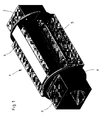
- FIG. 1 shows a separating device 1. It is essentially a Separier tanninfig 4, which has a square cross section in the illustrated embodiment. This is filled or emptied axially via two end regions 3, 2.
- the separating device is set up with an inclination against the horizontal and is rotated by driving the discs 6 about a central axis. Separating 5 serve to ensure that predetermined parts of a certain size fall through, while other parts pass through the drum axially and leave the drum again after task in area 3 and by migration in Separier tanninfig 4 in area 2.
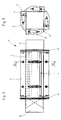
- FIG. 2 A top view is in FIG. 2 shown, in which it is shown that the separating openings 5 are openings of the cage, which are widened outwardly like a nozzle.
- These Separierkulissen 7 have adjustable walls in the embodiment shown and can be adjusted by adjusting devices 10.
- FIGS. 4 and 5 show details of this adjustment.
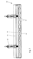
- FIG. 4 there is a Separierkulisse of a fixed wall 11 and a movable wall 12. Between the two Separierspalt 13 is formed.
- An adjusting device 10 is supported on an abutment wall 14.
- An abutment unit 15 ensures that a pin 16 is movable only up to a certain point.
- a spring 17 is inserted between counter bearing 14 and adjustable wall 12.
- the pin 16 is provided with the clamping ring 18 and abuts against a stop nut 19.
- a slot 20 of an outer sleeve movable Feder Kunststoffeinstellschraube 21 is mounted movable.
- the inner sleeve is adjustable against the spring pressure of the spring 17.
- FIG. 6 shows the top view of an alternative design of a Separierkulisse 30. Opposite the fixed wall 31, the wall 32 is movable. The slots 33 are separated by webs 34, so that individual Separierfelder 36 result. The adjustment of the movable wall 32 by means of an adjustment 35th
- FIG. 7 Another embodiment of a Separierkulisse is in FIG. 7 shown.
- a number of different separating openings 41 are formed in the slot through the use of geometry strips 42, 43, by means of which different parts can also be separated.
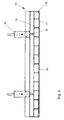
- FIG. 8 The details are in FIG. 8 according to which a first geometry strip 52 is fixed to the stationary wall 51. On the movable wall 54, the geometry strip 53 is arranged. Slot 62 is the chute into which separated elements passed by the geometry bars fail.
- the adjusting device has the inner sleeve 56 and the outer sleeve 58, in which a slot is formed, in which the spring pressure by means of the adjusting screw 57 is movable and adjustable.
- the stop of the pin 61 is formed over the clamping ring 59 and the stop nut 60.
- a Nutenkulisse be formed with an actuating pin. It is essential that inner sleeve and outer sleeve can be adjusted and fixed relative to each other.
- FIG. 9 shows an embodiment, wherein a per se conventional Separierkulisse 70 by a fixed wall 71 and a movable wall 72 which is adjustable in a conventional manner via the adjusting device, form the separating gap.
- the pin 73 is displaceable in the pin guide 74.
- the locking screw 75 is used for gap adjustment.
- An ejector 76 is guided in a guide opposite the fixed wall 71 and moves parallel to the slot, so that a body arranged thereon enters the slot and frees it from clamped parts.
- FIG. 10 shows a comparable embodiment, wherein the device 80 is supplemented by the exhaust nozzle 84. Instead of a mechanical element here compressed air or liquid media is fed into the gap. This is in FIG. 11 shown in detail where the exhaust nozzles 84 are formed on a nozzle bar 86.
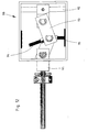
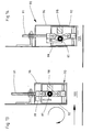
- FIGS. 12 to 14 show an alternative mechanical adjustment unit that reacts to gravity.
- a lockable and thus fixed unit 91 is coupled to a movable unit 92 in a housing 90.
- the hinge 93 falls due to gravity either on the pin 95 (opening stroke) or on the pin 94 (distance stroke).
- the pin 95 or the pin 94 bears against the wall of the housing 90, which means that the movable element 92 is in a different position via the link chain 93.
- the unit 90 comprises a movable inner housing 92 in the manner of a piston. This is movable with respect to an outer slide 96 in the manner of a cylinder.
- the pin 91 is hinged to the link chain 93 and serves the leadership.
- FIG. 13 is the chute 100 open. Due to gravity, the hinge weight 97 sits on the base 98 in the piston 92. In FIG. 14 Due to gravity, the hinge weight 97 rests on the stop 99, that is, the piston 92 is in the extended position and the separating gap has its functional working width.
Landscapes
- Combined Means For Separation Of Solids (AREA)
- Centrifugal Separators (AREA)
Priority Applications (1)
| Application Number | Priority Date | Filing Date | Title |
|---|---|---|---|
| EP20100008134 EP2415531B1 (fr) | 2010-08-04 | 2010-08-04 | Dispositif de séparation |
Applications Claiming Priority (1)
| Application Number | Priority Date | Filing Date | Title |
|---|---|---|---|
| EP20100008134 EP2415531B1 (fr) | 2010-08-04 | 2010-08-04 | Dispositif de séparation |
Publications (2)
| Publication Number | Publication Date |
|---|---|
| EP2415531A1 true EP2415531A1 (fr) | 2012-02-08 |
| EP2415531B1 EP2415531B1 (fr) | 2014-10-15 |
Family
ID=43303674
Family Applications (1)
| Application Number | Title | Priority Date | Filing Date |
|---|---|---|---|
| EP20100008134 Active EP2415531B1 (fr) | 2010-08-04 | 2010-08-04 | Dispositif de séparation |
Country Status (1)
| Country | Link |
|---|---|
| EP (1) | EP2415531B1 (fr) |
Cited By (1)
| Publication number | Priority date | Publication date | Assignee | Title |
|---|---|---|---|---|
| DE102015202633A1 (de) | 2015-02-13 | 2016-08-18 | Schaeffler Technologies AG & Co. KG | Vorrichtung zum Separieren von Spritzgussteilen und Angussteilen |
Families Citing this family (1)
| Publication number | Priority date | Publication date | Assignee | Title |
|---|---|---|---|---|
| DE102018112574A1 (de) | 2018-05-25 | 2019-11-28 | Schaeffler Technologies AG & Co. KG | Separiertrommel |
Citations (3)
| Publication number | Priority date | Publication date | Assignee | Title |
|---|---|---|---|---|
| GB1596515A (en) * | 1977-11-24 | 1981-08-26 | Knippi Niproruda | Separating solid materials |
| FR2543798A1 (fr) * | 1983-04-05 | 1984-10-12 | Cherreau Raymond | Dispositif de decolmatage automatique en marche continue, pour un egrappoir a vendange |
| EP1348495A2 (fr) * | 2002-03-28 | 2003-10-01 | Huning Umwelttechnik GmbH + Co. KG | Tamis avec éléments de tamisage pressés l'un contre l'autre |
-
2010
- 2010-08-04 EP EP20100008134 patent/EP2415531B1/fr active Active
Patent Citations (3)
| Publication number | Priority date | Publication date | Assignee | Title |
|---|---|---|---|---|
| GB1596515A (en) * | 1977-11-24 | 1981-08-26 | Knippi Niproruda | Separating solid materials |
| FR2543798A1 (fr) * | 1983-04-05 | 1984-10-12 | Cherreau Raymond | Dispositif de decolmatage automatique en marche continue, pour un egrappoir a vendange |
| EP1348495A2 (fr) * | 2002-03-28 | 2003-10-01 | Huning Umwelttechnik GmbH + Co. KG | Tamis avec éléments de tamisage pressés l'un contre l'autre |
Cited By (1)
| Publication number | Priority date | Publication date | Assignee | Title |
|---|---|---|---|---|
| DE102015202633A1 (de) | 2015-02-13 | 2016-08-18 | Schaeffler Technologies AG & Co. KG | Vorrichtung zum Separieren von Spritzgussteilen und Angussteilen |
Also Published As
| Publication number | Publication date |
|---|---|
| EP2415531B1 (fr) | 2014-10-15 |
Similar Documents
| Publication | Publication Date | Title |
|---|---|---|
| DE2813381A1 (de) | Druckfedernspanner | |
| EP0606555B1 (fr) | Assembleuse et brocheuse combinées pour produits imprimés constitués de feuilles imprimées pliées | |
| DE1276910B (de) | Reifenaufbautrommel mit Trommelsegmenten | |
| DE69609365T2 (de) | Vorrichtung zum Fördern von Münzen | |
| EP2937211A1 (fr) | Dispositif destiné à presser des récipients les uns contre les autres | |
| DE102015104719A1 (de) | Siebeinrichtung | |
| DE3528337C2 (fr) | ||
| EP2415531B1 (fr) | Dispositif de séparation | |
| DE102007050353A1 (de) | Greifvorrichtung | |
| DE9313610U1 (de) | Preßband-Separiereinrichtung | |
| DE69808608T2 (de) | Ein pneumatischer Impulsgenerator | |
| DE19603659C2 (de) | Vorrichtung zum Einschnüren und Abtrennen eines Stranges aus plastischem Material | |
| EP2890896B1 (fr) | Pompe haute pression à quatre soupapes | |
| DE3318797C2 (de) | Zellenradschleuse | |
| CH606751A5 (en) | Folding hollow slatted roller shutter | |
| EP0278333A2 (fr) | Dispositif de commande pour un séparateur de tuyau | |
| DE3134565A1 (de) | Stangenschere | |
| AT503389B1 (de) | Fleischwolf | |
| DE69917089T2 (de) | Spindel für Schleifbandstreifen und Vorrichtung, um denselben durch einen neuen Streifen auszutauschen | |
| CH636702A5 (en) | Process and device for metering liquid and pasty media, in particular colorants | |
| DE202019003540U1 (de) | Ventil | |
| DE10152676B4 (de) | Schließfolgeregler | |
| WO2016096953A1 (fr) | Appareil d'enfoncement muni d'un passage dans une chambre de combustion | |
| DE4115265C2 (de) | Mischer mit Absperreinheit | |
| DE3118440A1 (de) | Anordnung zum klassieren von stabartigen elementen, insbesondere parkettstaeben |
Legal Events
| Date | Code | Title | Description |
|---|---|---|---|
| 17P | Request for examination filed |
Effective date: 20110513 |
|
| AK | Designated contracting states |
Kind code of ref document: A1 Designated state(s): AL AT BE BG CH CY CZ DE DK EE ES FI FR GB GR HR HU IE IS IT LI LT LU LV MC MK MT NL NO PL PT RO SE SI SK SM TR |
|
| AX | Request for extension of the european patent |
Extension state: BA ME RS |
|
| PUAI | Public reference made under article 153(3) epc to a published international application that has entered the european phase |
Free format text: ORIGINAL CODE: 0009012 |
|
| 17Q | First examination report despatched |
Effective date: 20140212 |
|
| GRAP | Despatch of communication of intention to grant a patent |
Free format text: ORIGINAL CODE: EPIDOSNIGR1 |
|
| INTG | Intention to grant announced |
Effective date: 20140715 |
|
| GRAS | Grant fee paid |
Free format text: ORIGINAL CODE: EPIDOSNIGR3 |
|
| GRAA | (expected) grant |
Free format text: ORIGINAL CODE: 0009210 |
|
| AK | Designated contracting states |
Kind code of ref document: B1 Designated state(s): AL AT BE BG CH CY CZ DE DK EE ES FI FR GB GR HR HU IE IS IT LI LT LU LV MC MK MT NL NO PL PT RO SE SI SK SM TR |
|
| REG | Reference to a national code |
Ref country code: CH Ref legal event code: NV Representative=s name: E. BLUM AND CO. AG PATENT- UND MARKENANWAELTE , CH Ref country code: GB Ref legal event code: FG4D Free format text: NOT ENGLISH Ref country code: CH Ref legal event code: EP |
|
| REG | Reference to a national code |
Ref country code: IE Ref legal event code: FG4D Free format text: LANGUAGE OF EP DOCUMENT: GERMAN |
|
| REG | Reference to a national code |
Ref country code: AT Ref legal event code: REF Ref document number: 691386 Country of ref document: AT Kind code of ref document: T Effective date: 20141115 |
|
| REG | Reference to a national code |
Ref country code: DE Ref legal event code: R096 Ref document number: 502010008057 Country of ref document: DE Effective date: 20141127 |
|
| REG | Reference to a national code |
Ref country code: NL Ref legal event code: VDEP Effective date: 20141015 |
|
| REG | Reference to a national code |
Ref country code: LT Ref legal event code: MG4D |
|
| PG25 | Lapsed in a contracting state [announced via postgrant information from national office to epo] |
Ref country code: NL Free format text: LAPSE BECAUSE OF FAILURE TO SUBMIT A TRANSLATION OF THE DESCRIPTION OR TO PAY THE FEE WITHIN THE PRESCRIBED TIME-LIMIT Effective date: 20141015 |
|
| PG25 | Lapsed in a contracting state [announced via postgrant information from national office to epo] |
Ref country code: FI Free format text: LAPSE BECAUSE OF FAILURE TO SUBMIT A TRANSLATION OF THE DESCRIPTION OR TO PAY THE FEE WITHIN THE PRESCRIBED TIME-LIMIT Effective date: 20141015 Ref country code: LT Free format text: LAPSE BECAUSE OF FAILURE TO SUBMIT A TRANSLATION OF THE DESCRIPTION OR TO PAY THE FEE WITHIN THE PRESCRIBED TIME-LIMIT Effective date: 20141015 Ref country code: IS Free format text: LAPSE BECAUSE OF FAILURE TO SUBMIT A TRANSLATION OF THE DESCRIPTION OR TO PAY THE FEE WITHIN THE PRESCRIBED TIME-LIMIT Effective date: 20150215 Ref country code: NO Free format text: LAPSE BECAUSE OF FAILURE TO SUBMIT A TRANSLATION OF THE DESCRIPTION OR TO PAY THE FEE WITHIN THE PRESCRIBED TIME-LIMIT Effective date: 20150115 Ref country code: PT Free format text: LAPSE BECAUSE OF FAILURE TO SUBMIT A TRANSLATION OF THE DESCRIPTION OR TO PAY THE FEE WITHIN THE PRESCRIBED TIME-LIMIT Effective date: 20150216 Ref country code: ES Free format text: LAPSE BECAUSE OF FAILURE TO SUBMIT A TRANSLATION OF THE DESCRIPTION OR TO PAY THE FEE WITHIN THE PRESCRIBED TIME-LIMIT Effective date: 20141015 |
|
| PG25 | Lapsed in a contracting state [announced via postgrant information from national office to epo] |
Ref country code: GR Free format text: LAPSE BECAUSE OF FAILURE TO SUBMIT A TRANSLATION OF THE DESCRIPTION OR TO PAY THE FEE WITHIN THE PRESCRIBED TIME-LIMIT Effective date: 20150116 Ref country code: HR Free format text: LAPSE BECAUSE OF FAILURE TO SUBMIT A TRANSLATION OF THE DESCRIPTION OR TO PAY THE FEE WITHIN THE PRESCRIBED TIME-LIMIT Effective date: 20141015 Ref country code: CY Free format text: LAPSE BECAUSE OF FAILURE TO SUBMIT A TRANSLATION OF THE DESCRIPTION OR TO PAY THE FEE WITHIN THE PRESCRIBED TIME-LIMIT Effective date: 20141015 Ref country code: PL Free format text: LAPSE BECAUSE OF FAILURE TO SUBMIT A TRANSLATION OF THE DESCRIPTION OR TO PAY THE FEE WITHIN THE PRESCRIBED TIME-LIMIT Effective date: 20141015 Ref country code: SE Free format text: LAPSE BECAUSE OF FAILURE TO SUBMIT A TRANSLATION OF THE DESCRIPTION OR TO PAY THE FEE WITHIN THE PRESCRIBED TIME-LIMIT Effective date: 20141015 Ref country code: LV Free format text: LAPSE BECAUSE OF FAILURE TO SUBMIT A TRANSLATION OF THE DESCRIPTION OR TO PAY THE FEE WITHIN THE PRESCRIBED TIME-LIMIT Effective date: 20141015 |
|
| REG | Reference to a national code |
Ref country code: DE Ref legal event code: R097 Ref document number: 502010008057 Country of ref document: DE |
|
| PG25 | Lapsed in a contracting state [announced via postgrant information from national office to epo] |
Ref country code: SK Free format text: LAPSE BECAUSE OF FAILURE TO SUBMIT A TRANSLATION OF THE DESCRIPTION OR TO PAY THE FEE WITHIN THE PRESCRIBED TIME-LIMIT Effective date: 20141015 Ref country code: EE Free format text: LAPSE BECAUSE OF FAILURE TO SUBMIT A TRANSLATION OF THE DESCRIPTION OR TO PAY THE FEE WITHIN THE PRESCRIBED TIME-LIMIT Effective date: 20141015 Ref country code: DK Free format text: LAPSE BECAUSE OF FAILURE TO SUBMIT A TRANSLATION OF THE DESCRIPTION OR TO PAY THE FEE WITHIN THE PRESCRIBED TIME-LIMIT Effective date: 20141015 Ref country code: CZ Free format text: LAPSE BECAUSE OF FAILURE TO SUBMIT A TRANSLATION OF THE DESCRIPTION OR TO PAY THE FEE WITHIN THE PRESCRIBED TIME-LIMIT Effective date: 20141015 Ref country code: RO Free format text: LAPSE BECAUSE OF FAILURE TO SUBMIT A TRANSLATION OF THE DESCRIPTION OR TO PAY THE FEE WITHIN THE PRESCRIBED TIME-LIMIT Effective date: 20141015 |
|
| PLBE | No opposition filed within time limit |
Free format text: ORIGINAL CODE: 0009261 |
|
| STAA | Information on the status of an ep patent application or granted ep patent |
Free format text: STATUS: NO OPPOSITION FILED WITHIN TIME LIMIT |
|
| PG25 | Lapsed in a contracting state [announced via postgrant information from national office to epo] |
Ref country code: IT Free format text: LAPSE BECAUSE OF FAILURE TO SUBMIT A TRANSLATION OF THE DESCRIPTION OR TO PAY THE FEE WITHIN THE PRESCRIBED TIME-LIMIT Effective date: 20141015 |
|
| 26N | No opposition filed |
Effective date: 20150716 |
|
| PG25 | Lapsed in a contracting state [announced via postgrant information from national office to epo] |
Ref country code: SI Free format text: LAPSE BECAUSE OF FAILURE TO SUBMIT A TRANSLATION OF THE DESCRIPTION OR TO PAY THE FEE WITHIN THE PRESCRIBED TIME-LIMIT Effective date: 20141015 |
|
| PG25 | Lapsed in a contracting state [announced via postgrant information from national office to epo] |
Ref country code: MC Free format text: LAPSE BECAUSE OF FAILURE TO SUBMIT A TRANSLATION OF THE DESCRIPTION OR TO PAY THE FEE WITHIN THE PRESCRIBED TIME-LIMIT Effective date: 20141015 Ref country code: LU Free format text: LAPSE BECAUSE OF FAILURE TO SUBMIT A TRANSLATION OF THE DESCRIPTION OR TO PAY THE FEE WITHIN THE PRESCRIBED TIME-LIMIT Effective date: 20150804 |
|
| GBPC | Gb: european patent ceased through non-payment of renewal fee |
Effective date: 20150804 |
|
| REG | Reference to a national code |
Ref country code: IE Ref legal event code: MM4A |
|
| REG | Reference to a national code |
Ref country code: FR Ref legal event code: ST Effective date: 20160429 |
|
| PG25 | Lapsed in a contracting state [announced via postgrant information from national office to epo] |
Ref country code: GB Free format text: LAPSE BECAUSE OF NON-PAYMENT OF DUE FEES Effective date: 20150804 Ref country code: IE Free format text: LAPSE BECAUSE OF NON-PAYMENT OF DUE FEES Effective date: 20150804 |
|
| PG25 | Lapsed in a contracting state [announced via postgrant information from national office to epo] |
Ref country code: FR Free format text: LAPSE BECAUSE OF NON-PAYMENT OF DUE FEES Effective date: 20150831 |
|
| PG25 | Lapsed in a contracting state [announced via postgrant information from national office to epo] |
Ref country code: MT Free format text: LAPSE BECAUSE OF FAILURE TO SUBMIT A TRANSLATION OF THE DESCRIPTION OR TO PAY THE FEE WITHIN THE PRESCRIBED TIME-LIMIT Effective date: 20141015 |
|
| PG25 | Lapsed in a contracting state [announced via postgrant information from national office to epo] |
Ref country code: HU Free format text: LAPSE BECAUSE OF FAILURE TO SUBMIT A TRANSLATION OF THE DESCRIPTION OR TO PAY THE FEE WITHIN THE PRESCRIBED TIME-LIMIT; INVALID AB INITIO Effective date: 20100804 Ref country code: BG Free format text: LAPSE BECAUSE OF FAILURE TO SUBMIT A TRANSLATION OF THE DESCRIPTION OR TO PAY THE FEE WITHIN THE PRESCRIBED TIME-LIMIT Effective date: 20141015 Ref country code: SM Free format text: LAPSE BECAUSE OF FAILURE TO SUBMIT A TRANSLATION OF THE DESCRIPTION OR TO PAY THE FEE WITHIN THE PRESCRIBED TIME-LIMIT Effective date: 20141015 |
|
| PG25 | Lapsed in a contracting state [announced via postgrant information from national office to epo] |
Ref country code: BE Free format text: LAPSE BECAUSE OF NON-PAYMENT OF DUE FEES Effective date: 20150831 |
|
| PG25 | Lapsed in a contracting state [announced via postgrant information from national office to epo] |
Ref country code: TR Free format text: LAPSE BECAUSE OF FAILURE TO SUBMIT A TRANSLATION OF THE DESCRIPTION OR TO PAY THE FEE WITHIN THE PRESCRIBED TIME-LIMIT Effective date: 20141015 |
|
| REG | Reference to a national code |
Ref country code: DE Ref legal event code: R082 Ref document number: 502010008057 Country of ref document: DE Representative=s name: BRINKMANN & PARTNER PATENTANWAELTE PARTNERSCHA, DE Ref country code: DE Ref legal event code: R082 Ref document number: 502010008057 Country of ref document: DE Representative=s name: RAUSCH WANISCHECK-BERGMANN BRINKMANN PARTNERSC, DE |
|
| PG25 | Lapsed in a contracting state [announced via postgrant information from national office to epo] |
Ref country code: MK Free format text: LAPSE BECAUSE OF FAILURE TO SUBMIT A TRANSLATION OF THE DESCRIPTION OR TO PAY THE FEE WITHIN THE PRESCRIBED TIME-LIMIT Effective date: 20141015 |
|
| PG25 | Lapsed in a contracting state [announced via postgrant information from national office to epo] |
Ref country code: AL Free format text: LAPSE BECAUSE OF FAILURE TO SUBMIT A TRANSLATION OF THE DESCRIPTION OR TO PAY THE FEE WITHIN THE PRESCRIBED TIME-LIMIT Effective date: 20141015 |
|
| P01 | Opt-out of the competence of the unified patent court (upc) registered |
Effective date: 20230517 |
|
| PGFP | Annual fee paid to national office [announced via postgrant information from national office to epo] |
Ref country code: AT Payment date: 20250821 Year of fee payment: 16 |
|
| PGFP | Annual fee paid to national office [announced via postgrant information from national office to epo] |
Ref country code: CH Payment date: 20250901 Year of fee payment: 16 |
|
| PGFP | Annual fee paid to national office [announced via postgrant information from national office to epo] |
Ref country code: DE Payment date: 20251028 Year of fee payment: 16 |