EP2415558B1 - Machine de polissage tenue manuellement - Google Patents
Machine de polissage tenue manuellement Download PDFInfo
- Publication number
- EP2415558B1 EP2415558B1 EP11172636.0A EP11172636A EP2415558B1 EP 2415558 B1 EP2415558 B1 EP 2415558B1 EP 11172636 A EP11172636 A EP 11172636A EP 2415558 B1 EP2415558 B1 EP 2415558B1
- Authority
- EP
- European Patent Office
- Prior art keywords
- planetary gear
- polishing machine
- drive motor
- hand
- machine according
- Prior art date
- Legal status (The legal status is an assumption and is not a legal conclusion. Google has not performed a legal analysis and makes no representation as to the accuracy of the status listed.)
- Active
Links
Images


Classifications
-
- B—PERFORMING OPERATIONS; TRANSPORTING
- B24—GRINDING; POLISHING
- B24B—MACHINES, DEVICES, OR PROCESSES FOR GRINDING OR POLISHING; DRESSING OR CONDITIONING OF ABRADING SURFACES; FEEDING OF GRINDING, POLISHING, OR LAPPING AGENTS
- B24B23/00—Portable grinding machines, e.g. hand-guided; Accessories therefor
- B24B23/02—Portable grinding machines, e.g. hand-guided; Accessories therefor with rotating grinding tools; Accessories therefor
- B24B23/028—Angle tools
-
- B—PERFORMING OPERATIONS; TRANSPORTING
- B24—GRINDING; POLISHING
- B24B—MACHINES, DEVICES, OR PROCESSES FOR GRINDING OR POLISHING; DRESSING OR CONDITIONING OF ABRADING SURFACES; FEEDING OF GRINDING, POLISHING, OR LAPPING AGENTS
- B24B47/00—Drives or gearings; Equipment therefor
- B24B47/10—Drives or gearings; Equipment therefor for rotating or reciprocating working-spindles carrying grinding wheels or workpieces
- B24B47/12—Drives or gearings; Equipment therefor for rotating or reciprocating working-spindles carrying grinding wheels or workpieces by mechanical gearing or electric power
-
- B—PERFORMING OPERATIONS; TRANSPORTING
- B25—HAND TOOLS; PORTABLE POWER-DRIVEN TOOLS; MANIPULATORS
- B25F—COMBINATION OR MULTI-PURPOSE TOOLS NOT OTHERWISE PROVIDED FOR; DETAILS OR COMPONENTS OF PORTABLE POWER-DRIVEN TOOLS NOT PARTICULARLY RELATED TO THE OPERATIONS PERFORMED AND NOT OTHERWISE PROVIDED FOR
- B25F5/00—Details or components of portable power-driven tools not particularly related to the operations performed and not otherwise provided for
- B25F5/001—Gearings, speed selectors, clutches or the like specially adapted for rotary tools
Definitions
- the invention relates to a hand-held polishing machine, comprising a drive motor, a drive motor shaft which is driven directly by the drive motor, a polishing tool shaft which is oriented transversely to the drive motor shaft, and a reduction gear which is coupled to the drive motor shaft and the polishing tool shaft and which has at least two stages is, wherein the reduction gear comprises a planetary gear as a reduction stage.
- the reduction gear serves to reduce the speed of the drive motor shaft provided by the drive motor to a speed of the polishing tool shaft which is suitable for polishing operations.
- a speed is in particular of the order of 3,500 rpm.
- a hand tool gear in particular for an angle grinder, with a rotatably mounted drive shaft that can be driven by an electric motor and a rotatably mounted output shaft for driving a tool.
- a planetary gear is provided for torque transmission from the input shaft to the output shaft.
- a hand-held power tool with a motor housing and a gear housing, with an electric drive motor having a motor shaft being arranged in the motor housing
- Gear housing a gear with an angular gear and a tool spindle are arranged, and wherein the tool spindle is at an at least approximately right angle to the motor shaft and from the motor shaft is driven by the gearbox.
- the gear has a planetary gear.
- the invention is based on the object of providing a hand-held polishing machine of the type mentioned at the outset, which has advantageous handling properties.
- a reduction stage can be provided via the planetary gear, which has a coaxial axis of rotation to a drive motor shaft.
- This reduction stage is designed so that a drive train is in line with the drive motor shaft. This avoids a transverse offset in a housing of the polishing machine and the corresponding housing can be realized with a minimized height in the direction of the axis of rotation of the polishing tool shaft.
- the handling of the polishing machine which in particular has handle areas on the housing, is facilitated by a correspondingly flat housing; Due to the corresponding compact structure, a polishing process can be carried out in an optimized manner by a user.
- a rotation axis of the drive motor shaft and a main axis of the planetary gear are coaxial with each other.
- the main axis of the planetary gear is, for example, a corresponding axis of a sun gear of the planetary gear, the planetary gears of the planetary gear being orbital to the main axis.
- a locking device for locking a rotatability of the polishing tool shaft acts on the planetary gear carrier.
- a locking device is required in order to fix the polishing tool shaft in terms of its ability to rotate for a tool change.
- the locking device acts directly on the planetary gear carrier.
- an actuating element of the locking device which is actuated by a user, can be arranged outside of the gripping areas of the polishing machine. The risk of accidental locking, for example during operation of the polishing machine, is greatly reduced.
- a planetary gear carrier can be designed for locking in a simple manner, since a housing must already be present to hold the planetary gears anyway. Furthermore, in the case of forced locking when the machine is coasting down, the rotational speed and the rotational energy resulting therefrom are reduced, in particular on a rotor of the motor. Due to the resulting reduced torque, the force load on a locking pin is reduced.
- a sun gear of the planetary gear is non-rotatably connected to the drive motor shaft.
- the drive torque of the drive motor can be coupled into the planetary gear via the sun gear of the planetary gear.
- a ring gear of the planetary gear is arranged in a housing in a rotationally fixed manner. This allows a planetary gear carrier (web) rotate. The corresponding drive torque can be coupled into a further reduction stage.
- the ring gear has an external thread and is fixed in the housing with the external thread.
- the planetary gear can be assembled in a simple manner during manufacture of the polishing machine.
- the ring gear is arranged in a conical seat in the housing.
- a screw fixation of the ring gear can make an exact coaxial positioning to an axis of rotation of the drive motor shaft more difficult.
- a conical seat By providing a conical seat, a coaxial alignment with a high degree of accuracy can be implemented in a simple manner.
- the planetary gear carrier of the planetary gear on which a plurality of planetary gears is arranged, is rotatably mounted in a housing.
- the drive motor shaft drives the planetary gear carrier in rotation via a sun gear.
- the drive torque of the planetary gear carrier can then in turn be passed on to a further reduction stage of the reduction gear.
- the Planetary gear carrier can fulfill a number of tasks; it serves to attach a gear such as a bevel gear of a further reduction stage. It is used to center a sun gear. It provides a counter-element for storing planetary gears.
- the polishing tool shaft can be locked via the planetary gear carrier.
- drive torque is provided in the planetary gear carrier by a sun gear driven by the drive motor shaft. This allows a reduction stage to be implemented in a simple manner.
- the planetary gear carrier provides the drive torque to a further reduction stage of the reduction gear.
- the planetary gear carrier has a reduced speed with respect to a speed of the drive motor shaft. It has a higher speed than the polishing tool shaft.
- polishing tool shaft is then directly coupled to the further gear stage. This allows a two-stage reduction gear to be formed in a simple manner.
- the further reduction stage is an angular gear.
- bevel gears are bevel gears or crown gears. This makes it possible to realize a polishing machine which has a longitudinal extent in an axis which is in particular coaxial to an axis of rotation of the drive motor shaft, with an axis of rotation of a polishing tool lying transversely and in particular perpendicularly to this axis.
- a gear of a further reduction stage of the reduction gear is connected to the planetary gear carrier in a rotationally fixed manner.
- the gear is, for example, a bevel gear (of a bevel gear) or a face gear (of a face gear).
- an axis of rotation of the planetary gear carrier and an axis of rotation of the drive motor shaft are coaxial. Due to a linear arrangement of the corresponding reduction stage and the drive motor shaft, this results in a housing design with a minimized height in the direction of the axis of rotation of the polishing tool shaft.
- the locking device has an engagement element, which is formed, for example, like a pin, which in a corresponding Recess of the planetary gear carrier can be immersed in order to block its rotation. This allows the polishing tool shaft to be rotationally fixed in a simple manner by rotationally fixing the planetary gear carrier.
- a recess device with a recess is designed asymmetrically in relation to a direction of rotation of the planetary gear carrier.
- This asymmetrical design can be achieved in particular via the walls delimiting the recess.
- a running side of the recess has an elevation and, optionally, a running side of the recess also has a material reduction. This achieves a kind of engagement delay. Dipping of the engagement element into a recess should be prevented during operation of the polishing machine.
- a user can push the engagement member toward the planetary gear carrier and cause dipping by manually rotating the burnishing tool shaft.
- the manual rotation is slow.
- the increase in distance to the recess prevents immersion when the engagement element is in contact with the elevation, since immersion generally cannot occur during the brief period of rotation of the recess via the engagement element.
- an actuating element of the locking device is arranged in an area of the housing which surrounds the planet gear carrier.
- the actuating element of the locking device is an actuating device for a user.
- the actuating element is designed in the manner of a push button. If it is arranged in the area of the housing which surrounds the planetary gear carrier, then the engagement element can easily be immersed in a corresponding recess by means of a linear movement of the corresponding handle element, this linear movement being activated by acting on the actuating element.
- the operating element is arranged outside of a grip area for holding the polishing machine by a user during the polishing process. This minimizes the risk of unintentional actuation during a polishing process. This can be implemented in a simple manner by the action of the locking device on the planetary gear carrier.
- a sun gear of the planetary gear has a centering collar on one end. This allows the polishing machine to be manufactured in a simple manner.
- the sun gear can be brought into effective contact with a plurality of planetary gears of the planetary gear in a simple manner via the centering collar.
- a planet gear carrier then has a recess for the centering collar.
- the centering collar is positioned in this recess and advantageously does not touch the planet gear carrier when it rotates.
- planetary gears of the planetary gear are each arranged on a sleeve, and in particular a needle sleeve, which is seated on a planetary gear carrier. This allows the planetary gear to be manufactured in a simple manner.
- the sleeve is fixed to the planet gear carrier in each case via a pin element.
- the planetary gear can be manufactured in a simple manner.
- the drive motor advantageously provides a speed in the range between 20,000 rpm and 40,000 rpm.
- the drive motor shaft is driven at this speed.
- the reduction gear ensures a corresponding reduction.
- the planetary gear provides an output speed in the range between 5,000 rpm and 10,000 rpm.
- the high speed provided by the drive motor shaft is reduced to a medium speed.
- the polishing tool shaft has a speed in the range between 400 rpm and 3000 rpm and in particular in the range between 600 rpm and 2200 rpm. Preferably the speed is adjustable to suit a given workpiece. This results in optimized polishing results.
- a further reduction stage is provided between the planetary gear and the polishing tool shaft, which provides for the reduction from a medium speed to the lower speeds mentioned.
- the drive motor is an electric motor. This makes it easy to realize a compact, hand-held polishing machine.
- a housing area in which the drive motor is arranged provides a gripping area for a user of the polishing machine via its outer surface. A user can then grasp the polishing machine in this housing area. With the other hand he can hold the polishing machine in a head area.
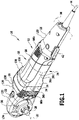
- the housing 12 comprises a first housing shell 14.
- a second housing shell 16 is fixed to the first housing shell 14.
- the second housing shell 16 (and optionally the first housing shell 14) is formed in two parts, for example, with a first part 18 and a second part 20.
- housing 12 has two housing shells and an enclosed area.
- the polishing machine 10 has three sections: a head 22, a middle section 24 which follows the head 22, and a tail section 26, with the middle section 24 lying between the head 22 and the tail section 26.
- the first part 18 of the second housing shell 16 closes the housing 12 at the head 22 and the second part 20 of the second housing shell 16 closes the housing 12 at the central area 24 and the end area 26.
- a polishing tool shaft 28 protrudes from the housing 12 and can be rotated about an axis of rotation 32 in a direction of rotation 30 .
- a polishing tool and in particular a polishing disk can be fixed to the polishing tool shaft 28 by means of suitable fixing means.
- the polishing tool shaft 28 projects beyond an underside 34 of the housing 12 .
- This underside 34 is formed by a corresponding shell part 36a of the first housing shell 14 and by corresponding shell parts 36b, 36c of the second housing shell 16.
- the axis of rotation 32 of the polishing tool shaft 28 lies on a central plane 38 of the polishing machine. At this center plane 38, the first housing shell 14 and the second housing shell 16 meet at least approximately. (The first housing shell 14 and/or the second housing shell 16 can have a fold or a fold recess for the tight closure of the housing 12.)
- a drive motor 40 which is an electric motor ( Figures 2 to 4 ).
- a switch 42 for activating/deactivating the drive motor 40 is arranged on the end region 26 .
- a corresponding circuit arrangement is positioned in the end region 26 in the housing 12 .
- a cable 44 leads to the connection of the polishing machine 10 to an electrical supply device and in particular to a power supply system in the end region 26.
- a reduction gear 46 is arranged, which is designed in two stages with a first reduction stage 48, which includes a planetary gear 50, and with a second reduction stage 52, which is serially connected to the first reduction stage 48 and includes an angular gear 54 ( figures 2 , 3 ).
- the polishing tool shaft 28 is coupled to the second gear reduction stage 52 .
- the polishing machine 10 includes a drive motor shaft 56 ( figure 4 ), which is rotatable about an axis of rotation 58.
- the axis of rotation 58 is transverse and in particular perpendicular to the axis of rotation 32 of the polishing tool shaft 28.
- the drive motor shaft 56 is part of the drive motor 40 or is coupled directly to the drive motor 40.
- the drive motor shaft 56 is connected via a bearing device 60 ( figure 6 ) stored in the housing 12. It is non-rotatably connected to a rotor (armature) 62 on which a laminated core 64 ( figure 4 ) sits.
- the drive motor 40 also has a stator 65 ( figure 3 ) on.
- the housing 12 is provided with air slots 66a, 66b ( figure 1 ) for air cooling of the drive motor 40, with air slots 66a being arranged on the head 22 and in particular on the underside 34 in the vicinity of the polishing tool shaft 28.
- Air slots 66b are arranged laterally on the housing 12 in the end region 26 . A flow of air sucked in by the rotor 62 can flow through the housing 12 in the area of the drive motor 40 between the air slots 66a and 66b.
- the drive motor shaft 56 has a speed which is on the order of 30,000 rpm.
- the reduction gear 46 slows the speed for the burnishing tool shaft 28 and specifically slows it down to a speed on the order of 2,000 rpm.
- the speed of the drive motor shaft 56 is reduced to a speed lying between the speed of the polishing tool shaft 28 and the drive motor shaft 56 . For example, there is a reduction to a speed of the order of magnitude of 7,000 rpm.
- the second reduction stage 52 starting from this speed, the final reduction to the effective speed of the polishing tool shaft 28 then takes place.
- a sun gear 68 ( Figures 4 to 6 ) of the planetary gear 50 connected. This sun gear 68 ensures that the drive motor shaft 56 is coupled to the planetary gear 50. An axis of rotation of the sun gear 68 corresponds to the axis of rotation of the drive motor shaft 56.
- the sun gear 68 has a centering collar 70 at its front end ( figures 4 , 6 ).
- the sun gear 68 has a diameter D 1 ( figure 6 ) on.
- the sun gear 68 has a diameter D 2 which is smaller than the diameter D 1 .
- This centering collar 70 facilitates assembly of the polishing machine 10 when a planetary gear carrier 72 ( figures 2 , 3 , 7 ) is to be placed on the sun gear 68 with engagement of planetary gears 74.
- the planet gear carrier 72 includes a cage 76 which holds a plurality of planet gears 74 .
- the planetary gears 74 each have an axis 78 which is oriented parallel to a main axis 80 of the planetary gear 50 .
- the main axis 80 is also a central axis of the planetary gear carrier 72 and the "sun center" for the planetary gears 74.
- the cage 76 has side windows 82 corresponding to the number of planet gears 74 .
- a planet gear 74 is partially immersed through the respective window 82 .
- a planet gear 74 has a recess 84 in which a sleeve 86 is positioned.
- the sleeve 86 is in particular pressed into the recess 84 so that the corresponding planet wheel 74 is fixed to the sleeve 86 by being pressed in.
- a pin element 88 which is fixed to the cage 76 is in turn seated on the sleeve 86 .
- the cage 76 has a disk element 90 .
- a ring member 92 Positioned opposite and spaced therefrom is a ring member 92 .
- the pin member 88 of the corresponding planetary gear 74 is fixed to the disk member 90 and to the opposed ring member 92 .
- the planetary gears 74 are seated between the disc member 90 and the ring member 92 with lands 94 connecting the disc member 90 and the ring member 92.
- the respective windows 82 are formed between adjacent webs 94 .
- a spindle extension 96 is formed on the disk element 90 . This spindle extension 76 is used for connection to the second stage 52 of the reduction gear 46.
- the ring element 92 has a penetration area 98 through which the sun gear 68 is immersed.
- the sun gear 68 meshes with the planetary gears 74.
- the planet gear carrier 72 is arranged in the housing 12 such that it can rotate about an axis of rotation 100 .
- the axis of rotation 100 is coaxial with the axis of rotation 58 of the drive motor shaft 56 and thus also coaxial with the main axis 80 of the planetary gear 50.
- the planet gear carrier 72 has a recess 97 ( figure 7 ) for the centering collar 70 of the sun gear 68.
- the centering collar 70 can dip into this recess 97 when the planetary gear carrier 72 is positioned correctly with respect to the sun gear 68 with engagement of the planetary gears 74 on the sun gear 68 .
- the recess 97 is preferably designed so that the sun gear 68 does not touch the planet gear carrier 72 in the area of the centering collar 70.
- a rotary bearing 102 is arranged around the drive motor shaft 56 between the sun gear 68 and the bearing device 60 ( figure 6 ), via which the planetary gear carrier 72 can be supported in this area without impeding the ability to rotate.
- a further rotary bearing 104 is arranged in the housing 12 and is in particular adjacent to the second reduction stage 52 of the reduction gear 46 , via which the planetary gear carrier 72 is rotatably supported in the area of the spindle extension 96 in the housing 12 .
- a ring gear 106 is positioned on the head 22 in a rotationally fixed manner in the housing 12 .
- the ring gear 106 has a toothing 108 which faces the planetary gears 74 of the planetary gear carrier 72 and is adapted to this.
- the toothing of the planetary gears 74 engages in this toothing 108 of the ring gear 106 .
- the rotation of the sun gear 68 by the drive motor shaft 56 causes a rotation of the planetary gear carrier 72 with the spindle extension 96 as a whole about the axis of rotation 100.
- the ring gear 106 which is non-rotatably arranged in the housing 12 and on which the planetary gears 74 act, represents a counter-element of the planetary gear 50.
- the translation of the planetary gear 50 is determined by the ratio of the number of teeth of the toothing 108 of the ring gear 106 to the number of teeth of the sun gear 68.
- the larger this ratio the larger the reduction, i.e. the smaller the speed of the planetary gear carrier 72 and thus of the spindle extension 96 compared to the speed of the drive motor shaft 56.
- the ratio of the speed of the sun gear 68 (and hence the drive motor shaft 56) to the speed of the spindle extension 96 is in the range of 3 to 5.
- a typical ratio for the number of teeth of the teeth 108 to the number of teeth of the sun gear 68 is of the order of 3.
- the ring gear 106 has an external thread 110 with which it is screwed in the housing 12 for non-rotatable fixing to a corresponding mating thread.
- a conical seat 112 is provided in this case in order to obtain an exact alignment of a central axis of the ring gear 106 coaxially to the axis of rotation 100 . Due to the screw fixation of the ring gear 106 in the housing 12 and the provision of the conical seat 112, the ring gear 106 can be fixed in a simple manner during the manufacture of the polishing machine 10 and an exact alignment can be achieved. (If the ring gear 106 is fixed in the housing 12 without a conical seat 112 only with an external thread, the alignment is less precise for manufacturing reasons.)
- Gears of the planetary gear 50 and in particular the planetary gears 74 are preferably made of a plastic material. As a result, a noise reduction can be achieved in comparison with metal gears.
- the sun gear 68 and ring gear 106 may be made of a plastic material or metal.
- a bevel gear 114 of the second reduction stage 52 of the reduction gear 46 sits on the spindle extension 96 and rotates about the axis of rotation 100 at the speed of the planetary gear carrier 72 .
- the planetary gear 50 is coupled to the bevel gear 54 via the bevel gear 114 .
- a ring gear 116 aligned coaxially to the axis of rotation 28 and on which the bevel gear 114 engages, is seated on the polishing tool shaft 28 in a rotationally fixed manner.
- An angular gear 54 is implemented as a bevel gear via the bevel gear 114 and the ring gear 116 .
- the polishing machine 10 has a locking device 118 for non-rotatably fixing the polishing tool shaft 28 for a tool change or for inserting a tool.
- the locking device 118 is designed in such a way that it acts on the planet gear carrier 72 and fixes it in a rotationally fixed manner. This non-rotatable fixing causes a non-rotatable fixing of the polishing tool shaft 28 via the second reduction stage 52 of the reduction gear 46.
- the locking device 118 has an engagement element 120 arranged on the head 22 above the planet gear carrier 74 , for example in the form of a pin element 120 .
- This pin element 120 is supported by a spring 122 .
- the spring 122 tends to push a lower end of the pin member 120 away from the planetary gear carrier 72 in a direction transverse to the axis of rotation 100 .
- an operator In order to move the lower end of the pin element 120 in the corresponding opposite direction, an operator must exert a corresponding force on an actuating element 124 .
- the actuating element 124 is designed in particular as a head which is seated on the pin element 120 and can be actuated from an outside of the housing 12 in the manner of a push button.
- the planet gear carrier 74 has a recess device with recesses 126 at a distance from the ring element 92, into which the pin element 120 can dip. When a pin element 120 has entered a corresponding recess 126, the rotation of the planetary gear carrier 72 and thus also the rotation of the polishing tool shaft 28 is blocked.
- the housing 12 has a rounded transition step 130 on a top surface 128 opposite the underside 34 at the head 22.
- the height of the housing 12 increases in a height direction which is parallel to the direction of the axis of rotation 32.
- the bevel gear 54 is arranged in the area with the lower height. In that area the planetary gear 50 is arranged with the greater height.
- a grip area is formed for a user to hold the polishing machine 10 when polishing, that is, the area 132 is a holding area.
- the housing 12 is rounded at one end 134 .
- the housing 12 also has a handle area 136 in the middle area 24 for a user.
- a hand slip guard 138 can be arranged on the grip area 136 , which is formed, for example, by an elevation on an outer side of the housing 12 .
- Another grip area 139 is formed on the end area 26 .
- a user can grasp the grip portion 139 with one hand and grasp the portion 132 with the other hand.
- the actuating element 124 is arranged outside of the area 132 and outside of the gripping area 139 . This reduces the risk of unintentional actuation.
- the locking device 118 is arranged in particular on the housing 12 in an area which surrounds the planetary gear carrier 72 and in particular its ring element 92 .
- the recess device for immersing the pin element 120 is designed asymmetrically with respect to a direction of rotation of the planetary gear carrier 72.
- the locking device 118 acts on a "medium speed range", namely also the planetary gear carrier 72.
- an elevation 140 is assigned to the recesses 126 on corresponding boundary walls on an incoming side and an elevation 142 is assigned to the opposite outgoing side. If during rotation of the planetary gear carrier 72 may inadvertently the pin member 120 in the direction of the ring member 92 is pressed, a ridge 140 prevents entry into the corresponding recess 126 and thereby an abrupt stop of the planetary gear carrier 72 due to engagement delay.
- Locking is usually effected in such a way that, when the drive motor shaft 56 is stationary, the pin element 120 is moved in the direction of the planetary gear carrier 72 by exerting force on the actuating element 124, and the polishing tool shaft 28 is rotated manually by the user until the pin element 120 can enter a corresponding recess 126. If the rotation of the planetary gear carrier 72 is sufficiently slow, as is achieved, for example, by manual rotation of the polishing tool shaft 28, then immersion and thus blocking of rotation can occur.
- the riser 140 on the leading side causes a sort of time lag for the plunge of the pin member 120.
- the planet carrier 72 has so rotated further so that no immersion can take place since the recess 126 has moved past the pin element 120 .
- the hand-held polishing machine 10 functions as follows: A multi-stage and in particular two-stage reduction gear 46 is provided between the drive motor 40 and the polishing tool shaft 28 . This is coupled to the drive motor shaft 56 on the input side and to the polishing tool shaft 28 on the output side. On the input side, the reduction gear 46 is acted upon by the drive torque and the speed of the drive motor shaft 56 . On the output side (output side), the reduction gear 46 provides the polishing tool shaft 28 and thus a corresponding polishing tool with the drive torque with a Reduction gear 46 set speed, which is less than the speed of the drive motor shaft 56.
- the first reduction stage 48 of the reduction gear 46 which is coupled to the drive motor shaft 56, is a planetary gear 50.
- This makes it possible to rotate the axis of rotation 58 of the drive motor shaft 56 and the axis of rotation 100 of the bevel gear 114 of the second stage 52 of the reduction gear 46 to be arranged in a line, i.e. coaxially.
- This makes it possible to design the housing with a relatively small height in the direction of the axis of rotation 32 of the polishing tool shaft 28 .
- This makes it possible to provide a flat housing 12 when the output speed of the polishing tool shaft 28 is low. This in turn allows the polisher 10 to be held close to the central portion 24 of the housing 12 by hand. This results in easy handling for a user.
- the planetary gear carrier 74 of the planetary gear 50 transmits the drive torque of the drive motor shaft 56 to the bevel gear 114 of the bevel gear 54.
- the planetary gear carrier 72 is therefore used to fasten and drive the bevel gear 114. It is a counter-element for the bearing of the planetary gears 74. It is used to center the sun gear 68.
- the locking device 118 also acts on the planetary gear carrier 72 so that a corresponding actuating element 124 is far removed from a grip area 132 on the head 22 and then accordingly the housing 12 can be formed there with minimized dimensions.
- the bevel gear 54 does not have to be designed in such a way that a locking device can act on it.
- the cage 76 that is present anyway for the planet gear carrier 72 can also be used for the locking device 118 with corresponding recesses 126 .
Landscapes
- Engineering & Computer Science (AREA)
- Mechanical Engineering (AREA)
- Finish Polishing, Edge Sharpening, And Grinding By Specific Grinding Devices (AREA)
- Constituent Portions Of Griding Lathes, Driving, Sensing And Control (AREA)
Claims (15)
- Polisseuse tenue à la main, comprenant un moteur d'entraînement (40), un arbre de moteur d'entraînement (56) entraîné directement par le moteur d'entraînement (40), un arbre d'outil de polissage (28) orienté transversalement à l'arbre de moteur d'entraînement (56) et un réducteur (46) qui est couplé à l'arbre de moteur d'entraînement (56) et à l'arbre d'outil de polissage (28) et qui est au moins à deux étages, le réducteur (46) comprenant un engrenage planétaire (50) en tant qu'étage de réduction (48), caractérisée en ce qu'un axe de rotation (58) de l'arbre de moteur d'entraînement (56) et un axe principal (80) de l'engrenage planétaire (50) sont coaxiaux et en ce qu'un dispositif de blocage (118) agit pour bloquer la rotation de l'arbre d'outil de polissage (28) sur le support de roue dentée planétaire (72).
- Polisseuse tenue à la main selon la revendication 1, caractérisée en ce qu'une roue dentée solaire (68) de l'engrenage planétaire (50) est reliée de manière solidaire en rotation à l'arbre de moteur d'entraînement (56).
- Polisseuse tenue à la main selon l'une des revendications précédentes, caractérisée en ce qu'une roue dentée creuse (106) de l'engrenage planétaire (50) est disposée de manière solidaire en rotation dans un boîtier (12), et en particulier en ce que la roue dentée creuse (106) présente un filetage extérieur (110) et est fixée avec le filetage extérieur (110) dans le boîtier (12), et en particulier en ce que la roue dentée creuse (106) est disposée dans le boîtier (12) dans un siège conique (112).
- Polisseuse tenue à la main selon l'une des revendications précédentes, caractérisée en ce qu'un support de roue dentée planétaire (72) de l'engrenage planétaire (50), sur lequel sont disposées une pluralité de roues dentées planétaires (74), est monté de manière à pouvoir tourner dans un boîtier (12), et en particulier en ce que le support de roue dentée planétaire (72) est pourvu d'un couple d'entraînement par une roue dentée solaire (68) entraînée par l'arbre de moteur d'entraînement (56), et en particulier en ce que le support de roue dentée planétaire (74) d'un autre étage de réduction (52) du réducteur (46) fournit le couple d'entraînement, et en particulier en ce que l'arbre d'outil de polissage (28) est directement couplé à l'autre étage de réduction (52).
- Polisseuse tenue à la main selon la revendication 4, caractérisée en ce que l'autre étage de réduction (52) comprend un engrenage angulaire (54).
- Polisseuse tenue à la main selon la revendication 4 ou 5, caractérisée en ce qu'une roue dentée (114) d'un autre étage de réduction (52) du réducteur (46) est reliée de manière solidaire en rotation au support de roue dentée planétaire (72).
- Polisseuse tenue à la main selon l'une des revendications 4 à 6, caractérisée en ce qu'un axe de rotation (100) du support de roue dentée planétaire (52) et un axe de rotation (58) de l'arbre de moteur d'entraînement (56) sont coaxiaux.
- Polisseuse tenue à la main selon l'une des revendications 4 à 7, caractérisée en ce que le dispositif de blocage (118) présente un élément de mise en prise (120) qui peut plonger dans un évidement (126) correspondant du support de roue dentée planétaire (72) afin d'empêcher sa rotation, et en particulier en ce qu'un dispositif d'évidement comportant un évidement (126) est réalisé de manière asymétrique par rapport à un sens de rotation du support de roue dentée planétaire (72), et en particulier en ce qu'un élément d'actionnement (124) du dispositif de blocage (118) est disposé dans une zone du boîtier (12) qui entoure le support de roue dentée planétaire (72), et en particulier en ce que l'élément d'actionnement (124) est disposé à l'extérieur d'une zone de préhension (132) permettant à un utilisateur de tenir la polisseuse lors d'un processus de polissage.
- Polisseuse tenue à la main selon l'une des revendications précédentes, caractérisée en ce qu'une roue dentée solaire (68) de l'engrenage planétaire (50) présente un collet de centrage (70) sur une face frontale, et en particulier en ce qu'un support de roue dentée planétaire (72) présente un évidement (97) pour le collet de centrage (70).
- Polisseuse tenue à la main selon l'une des revendications précédentes, caractérisée en ce que des roues dentées planétaires (74) de l'engrenage planétaire (50) sont respectivement disposées sur une douille (86) qui repose sur un support de roue dentée planétaire (72), et en particulier en ce que la douille (86) est respectivement fixée sur le support de roue dentée planétaire (72) par l'intermédiaire d'un élément de goupille (88), et en particulier en ce qu'une douille (86) est fixée sur la roue dentée planétaire (74) associée par ajustement serré.
- Polisseuse tenue à la main selon l'une des revendications précédentes, caractérisée en ce que le moteur d'entraînement (40) fournit une vitesse de rotation dans une plage comprise entre 20 000 tr/min et 40 000 tr/min.
- Polisseuse tenue à la main selon l'une des revendications précédentes, caractérisée en ce que l'engrenage planétaire (50) fournit une vitesse de rotation de sortie dans une plage comprise entre 5 000 tr/min et 10 000 tr/min.
- Polisseuse tenue à la main selon l'une des revendications précédentes, caractérisée en ce que l'arbre d'outil de polissage (28) présente une vitesse de rotation dans une plage comprise entre 400 tr/min et 3 000 tr/min et en particulier dans une plage comprise entre 600 tr/min et 2 200 tr/min.
- Polisseuse tenue à la main selon l'une des revendications précédentes, caractérisée en ce que le moteur d'entraînement (40) est un moteur électrique.
- Polisseuse tenue à la main selon l'une des revendications précédentes, caractérisée en ce qu'une zone de boîtier dans laquelle est disposé le moteur d'entraînement (40) fournit une zone de préhension (139) à un utilisateur de la polisseuse sur sa surface extérieure.
Applications Claiming Priority (1)
| Application Number | Priority Date | Filing Date | Title |
|---|---|---|---|
| DE102010038976A DE102010038976A1 (de) | 2010-08-05 | 2010-08-05 | Handgehaltene Poliermaschine |
Publications (3)
| Publication Number | Publication Date |
|---|---|
| EP2415558A2 EP2415558A2 (fr) | 2012-02-08 |
| EP2415558A3 EP2415558A3 (fr) | 2016-07-13 |
| EP2415558B1 true EP2415558B1 (fr) | 2022-10-26 |
Family
ID=44583980
Family Applications (1)
| Application Number | Title | Priority Date | Filing Date |
|---|---|---|---|
| EP11172636.0A Active EP2415558B1 (fr) | 2010-08-05 | 2011-07-05 | Machine de polissage tenue manuellement |
Country Status (2)
| Country | Link |
|---|---|
| EP (1) | EP2415558B1 (fr) |
| DE (1) | DE102010038976A1 (fr) |
Families Citing this family (2)
| Publication number | Priority date | Publication date | Assignee | Title |
|---|---|---|---|---|
| EP3450099A1 (fr) * | 2017-08-28 | 2019-03-06 | Siprotool AG | Machine de meulage de surface destinée au meulage et au polissage du sol |
| CN114888682B (zh) * | 2022-03-11 | 2025-11-25 | 江苏明文工具科技有限公司 | 一种扁头角磨机 |
Family Cites Families (7)
| Publication number | Priority date | Publication date | Assignee | Title |
|---|---|---|---|---|
| GB1130679A (en) * | 1966-10-11 | 1968-10-16 | Atlas Copco Ab | Improvements in rotary pneumatic nut runners and like tools |
| US6102632A (en) * | 1998-04-23 | 2000-08-15 | Black & Decker Inc. | Two speed right angle drill |
| DE10047312A1 (de) * | 2000-09-25 | 2002-05-08 | Hilti Ag | Steuerbares Planetengetriebe |
| DE10258863A1 (de) * | 2002-12-17 | 2004-07-08 | Robert Bosch Gmbh | Handwerkzeugmaschinengetriebe und Handwerkzeugmaschine |
| US20050279519A1 (en) * | 2004-06-17 | 2005-12-22 | One World Technologies Limited | Right angle impact driver |
| WO2008014806A1 (fr) * | 2006-08-02 | 2008-02-07 | A & M Electric Tools Gmbh | Outil électronique guidé à la main avec un engrenage planétaire |
| JP2009220202A (ja) * | 2008-03-14 | 2009-10-01 | Techway Industrial Co Ltd | 電気式研磨ガン |
-
2010
- 2010-08-05 DE DE102010038976A patent/DE102010038976A1/de not_active Withdrawn
-
2011
- 2011-07-05 EP EP11172636.0A patent/EP2415558B1/fr active Active
Also Published As
| Publication number | Publication date |
|---|---|
| EP2415558A3 (fr) | 2016-07-13 |
| EP2415558A2 (fr) | 2012-02-08 |
| DE102010038976A1 (de) | 2012-02-09 |
Similar Documents
| Publication | Publication Date | Title |
|---|---|---|
| EP2627483B1 (fr) | Outil électrique à main doté d'un dispositif verrou de broche | |
| DE19940369C2 (de) | Elektrisch antreibbare Zahnbürste | |
| DE10109741A1 (de) | Verbesserter Kupplungsmechanismus zur Verwendung in Rotationswerkzeugen mit Schraub-und Bohrbetrieb | |
| EP3027361A1 (fr) | Machine-outil équipée d'un dispositif de réception d'outil | |
| EP0401548A1 (fr) | Dispositif à outil de vissage | |
| EP0868264B1 (fr) | Outil a main electrique | |
| DE3636229A1 (de) | Elektrisches handwerkzeug | |
| WO2002062526A1 (fr) | Machine-outil portative de meulage, polissage ou analogue | |
| DE10016706A1 (de) | Startvorrichtung | |
| DE4218683C2 (de) | Handstückkopf für ein zahnärztliches Handstück, mit einem Gehäuse, in dem ein Behandlungswerkzeug axial längs seiner Mittelachse hin und her verschiebbar gelagert ist | |
| EP3481593B1 (fr) | Système de machine-outil portative | |
| DE102012212404B4 (de) | Handwerkzeugmaschinenvorrichtung | |
| DE4101705C2 (de) | Handgeführte Elektrowerkzeugmaschine mit einer Einrichtung zum schnellen Stillsetzen des Werkzeuges | |
| EP3481590B1 (fr) | Système de machine-outil portative | |
| DE3247421A1 (de) | Antriebsvorrichtung, insbesondere fuer scheibenwischer von kraftfahrzeugen | |
| EP2415558A2 (fr) | Machine de polissage tenue manuellement | |
| EP0995551B1 (fr) | Outil à main, notamment visseuse ou perçeuse | |
| DE102010064363B4 (de) | Handwerkzeugmaschinenspannvorrichtung mit Verdrehsicherung | |
| DE102014216441A1 (de) | Handwerkzeugmaschine | |
| DE19719923C2 (de) | Bohr-, Bohrschraub- oder Schlagbohrmaschine | |
| EP3895846A1 (fr) | Tournevis de construction à sec | |
| DE4329181A1 (de) | Antriebsvorrichtung für einen zahnärztlichen Werkzeughalter | |
| DE10258863A1 (de) | Handwerkzeugmaschinengetriebe und Handwerkzeugmaschine | |
| DE69705377T2 (de) | Antrieb, insbesondere für eine elektrische Fahrzeugdiebstahlsicherung | |
| EP2655020A1 (fr) | Système de transmission pour un outil électrique et outil électrique |
Legal Events
| Date | Code | Title | Description |
|---|---|---|---|
| AK | Designated contracting states |
Kind code of ref document: A2 Designated state(s): AL AT BE BG CH CY CZ DE DK EE ES FI FR GB GR HR HU IE IS IT LI LT LU LV MC MK MT NL NO PL PT RO RS SE SI SK SM TR |
|
| AX | Request for extension of the european patent |
Extension state: BA ME |
|
| PUAI | Public reference made under article 153(3) epc to a published international application that has entered the european phase |
Free format text: ORIGINAL CODE: 0009012 |
|
| TPAC | Observations filed by third parties |
Free format text: ORIGINAL CODE: EPIDOSNTIPA |
|
| PUAL | Search report despatched |
Free format text: ORIGINAL CODE: 0009013 |
|
| AK | Designated contracting states |
Kind code of ref document: A3 Designated state(s): AL AT BE BG CH CY CZ DE DK EE ES FI FR GB GR HR HU IE IS IT LI LT LU LV MC MK MT NL NO PL PT RO RS SE SI SK SM TR |
|
| AX | Request for extension of the european patent |
Extension state: BA ME |
|
| RIC1 | Information provided on ipc code assigned before grant |
Ipc: B24B 23/02 20060101AFI20160608BHEP Ipc: B24B 47/00 20060101ALI20160608BHEP Ipc: B25F 5/00 20060101ALI20160608BHEP Ipc: B24B 47/12 20060101ALI20160608BHEP |
|
| STAA | Information on the status of an ep patent application or granted ep patent |
Free format text: STATUS: REQUEST FOR EXAMINATION WAS MADE |
|
| 17P | Request for examination filed |
Effective date: 20170110 |
|
| RBV | Designated contracting states (corrected) |
Designated state(s): AL AT BE BG CH CY CZ DE DK EE ES FI FR GB GR HR HU IE IS IT LI LT LU LV MC MK MT NL NO PL PT RO RS SE SI SK SM TR |
|
| STAA | Information on the status of an ep patent application or granted ep patent |
Free format text: STATUS: EXAMINATION IS IN PROGRESS |
|
| 17Q | First examination report despatched |
Effective date: 20191127 |
|
| GRAP | Despatch of communication of intention to grant a patent |
Free format text: ORIGINAL CODE: EPIDOSNIGR1 |
|
| STAA | Information on the status of an ep patent application or granted ep patent |
Free format text: STATUS: GRANT OF PATENT IS INTENDED |
|
| INTG | Intention to grant announced |
Effective date: 20220519 |
|
| GRAS | Grant fee paid |
Free format text: ORIGINAL CODE: EPIDOSNIGR3 |
|
| GRAA | (expected) grant |
Free format text: ORIGINAL CODE: 0009210 |
|
| STAA | Information on the status of an ep patent application or granted ep patent |
Free format text: STATUS: THE PATENT HAS BEEN GRANTED |
|
| AK | Designated contracting states |
Kind code of ref document: B1 Designated state(s): AL AT BE BG CH CY CZ DE DK EE ES FI FR GB GR HR HU IE IS IT LI LT LU LV MC MK MT NL NO PL PT RO RS SE SI SK SM TR |
|
| REG | Reference to a national code |
Ref country code: GB Ref legal event code: FG4D Free format text: NOT ENGLISH |
|
| REG | Reference to a national code |
Ref country code: CH Ref legal event code: EP |
|
| REG | Reference to a national code |
Ref country code: DE Ref legal event code: R096 Ref document number: 502011017385 Country of ref document: DE |
|
| REG | Reference to a national code |
Ref country code: AT Ref legal event code: REF Ref document number: 1526717 Country of ref document: AT Kind code of ref document: T Effective date: 20221115 |
|
| REG | Reference to a national code |
Ref country code: IE Ref legal event code: FG4D Free format text: LANGUAGE OF EP DOCUMENT: GERMAN |
|
| REG | Reference to a national code |
Ref country code: NL Ref legal event code: FP |
|
| REG | Reference to a national code |
Ref country code: LT Ref legal event code: MG9D |
|
| PG25 | Lapsed in a contracting state [announced via postgrant information from national office to epo] |
Ref country code: SE Free format text: LAPSE BECAUSE OF FAILURE TO SUBMIT A TRANSLATION OF THE DESCRIPTION OR TO PAY THE FEE WITHIN THE PRESCRIBED TIME-LIMIT Effective date: 20221026 Ref country code: PT Free format text: LAPSE BECAUSE OF FAILURE TO SUBMIT A TRANSLATION OF THE DESCRIPTION OR TO PAY THE FEE WITHIN THE PRESCRIBED TIME-LIMIT Effective date: 20230227 Ref country code: NO Free format text: LAPSE BECAUSE OF FAILURE TO SUBMIT A TRANSLATION OF THE DESCRIPTION OR TO PAY THE FEE WITHIN THE PRESCRIBED TIME-LIMIT Effective date: 20230126 Ref country code: LT Free format text: LAPSE BECAUSE OF FAILURE TO SUBMIT A TRANSLATION OF THE DESCRIPTION OR TO PAY THE FEE WITHIN THE PRESCRIBED TIME-LIMIT Effective date: 20221026 Ref country code: FI Free format text: LAPSE BECAUSE OF FAILURE TO SUBMIT A TRANSLATION OF THE DESCRIPTION OR TO PAY THE FEE WITHIN THE PRESCRIBED TIME-LIMIT Effective date: 20221026 Ref country code: ES Free format text: LAPSE BECAUSE OF FAILURE TO SUBMIT A TRANSLATION OF THE DESCRIPTION OR TO PAY THE FEE WITHIN THE PRESCRIBED TIME-LIMIT Effective date: 20221026 |
|
| PG25 | Lapsed in a contracting state [announced via postgrant information from national office to epo] |
Ref country code: RS Free format text: LAPSE BECAUSE OF FAILURE TO SUBMIT A TRANSLATION OF THE DESCRIPTION OR TO PAY THE FEE WITHIN THE PRESCRIBED TIME-LIMIT Effective date: 20221026 Ref country code: PL Free format text: LAPSE BECAUSE OF FAILURE TO SUBMIT A TRANSLATION OF THE DESCRIPTION OR TO PAY THE FEE WITHIN THE PRESCRIBED TIME-LIMIT Effective date: 20221026 Ref country code: LV Free format text: LAPSE BECAUSE OF FAILURE TO SUBMIT A TRANSLATION OF THE DESCRIPTION OR TO PAY THE FEE WITHIN THE PRESCRIBED TIME-LIMIT Effective date: 20221026 Ref country code: IS Free format text: LAPSE BECAUSE OF FAILURE TO SUBMIT A TRANSLATION OF THE DESCRIPTION OR TO PAY THE FEE WITHIN THE PRESCRIBED TIME-LIMIT Effective date: 20230226 Ref country code: HR Free format text: LAPSE BECAUSE OF FAILURE TO SUBMIT A TRANSLATION OF THE DESCRIPTION OR TO PAY THE FEE WITHIN THE PRESCRIBED TIME-LIMIT Effective date: 20221026 Ref country code: GR Free format text: LAPSE BECAUSE OF FAILURE TO SUBMIT A TRANSLATION OF THE DESCRIPTION OR TO PAY THE FEE WITHIN THE PRESCRIBED TIME-LIMIT Effective date: 20230127 |
|
| REG | Reference to a national code |
Ref country code: DE Ref legal event code: R097 Ref document number: 502011017385 Country of ref document: DE |
|
| PG25 | Lapsed in a contracting state [announced via postgrant information from national office to epo] |
Ref country code: SM Free format text: LAPSE BECAUSE OF FAILURE TO SUBMIT A TRANSLATION OF THE DESCRIPTION OR TO PAY THE FEE WITHIN THE PRESCRIBED TIME-LIMIT Effective date: 20221026 Ref country code: RO Free format text: LAPSE BECAUSE OF FAILURE TO SUBMIT A TRANSLATION OF THE DESCRIPTION OR TO PAY THE FEE WITHIN THE PRESCRIBED TIME-LIMIT Effective date: 20221026 Ref country code: EE Free format text: LAPSE BECAUSE OF FAILURE TO SUBMIT A TRANSLATION OF THE DESCRIPTION OR TO PAY THE FEE WITHIN THE PRESCRIBED TIME-LIMIT Effective date: 20221026 Ref country code: DK Free format text: LAPSE BECAUSE OF FAILURE TO SUBMIT A TRANSLATION OF THE DESCRIPTION OR TO PAY THE FEE WITHIN THE PRESCRIBED TIME-LIMIT Effective date: 20221026 Ref country code: CZ Free format text: LAPSE BECAUSE OF FAILURE TO SUBMIT A TRANSLATION OF THE DESCRIPTION OR TO PAY THE FEE WITHIN THE PRESCRIBED TIME-LIMIT Effective date: 20221026 |
|
| PG25 | Lapsed in a contracting state [announced via postgrant information from national office to epo] |
Ref country code: SK Free format text: LAPSE BECAUSE OF FAILURE TO SUBMIT A TRANSLATION OF THE DESCRIPTION OR TO PAY THE FEE WITHIN THE PRESCRIBED TIME-LIMIT Effective date: 20221026 Ref country code: AL Free format text: LAPSE BECAUSE OF FAILURE TO SUBMIT A TRANSLATION OF THE DESCRIPTION OR TO PAY THE FEE WITHIN THE PRESCRIBED TIME-LIMIT Effective date: 20221026 |
|
| PLBE | No opposition filed within time limit |
Free format text: ORIGINAL CODE: 0009261 |
|
| STAA | Information on the status of an ep patent application or granted ep patent |
Free format text: STATUS: NO OPPOSITION FILED WITHIN TIME LIMIT |
|
| 26N | No opposition filed |
Effective date: 20230727 |
|
| PGFP | Annual fee paid to national office [announced via postgrant information from national office to epo] |
Ref country code: IT Payment date: 20230731 Year of fee payment: 13 Ref country code: GB Payment date: 20230724 Year of fee payment: 13 |
|
| PG25 | Lapsed in a contracting state [announced via postgrant information from national office to epo] |
Ref country code: SI Free format text: LAPSE BECAUSE OF FAILURE TO SUBMIT A TRANSLATION OF THE DESCRIPTION OR TO PAY THE FEE WITHIN THE PRESCRIBED TIME-LIMIT Effective date: 20221026 |
|
| PGFP | Annual fee paid to national office [announced via postgrant information from national office to epo] |
Ref country code: DE Payment date: 20230720 Year of fee payment: 13 |
|
| PG25 | Lapsed in a contracting state [announced via postgrant information from national office to epo] |
Ref country code: MC Free format text: LAPSE BECAUSE OF FAILURE TO SUBMIT A TRANSLATION OF THE DESCRIPTION OR TO PAY THE FEE WITHIN THE PRESCRIBED TIME-LIMIT Effective date: 20221026 |
|
| PG25 | Lapsed in a contracting state [announced via postgrant information from national office to epo] |
Ref country code: MC Free format text: LAPSE BECAUSE OF FAILURE TO SUBMIT A TRANSLATION OF THE DESCRIPTION OR TO PAY THE FEE WITHIN THE PRESCRIBED TIME-LIMIT Effective date: 20221026 |
|
| REG | Reference to a national code |
Ref country code: CH Ref legal event code: PL |
|
| REG | Reference to a national code |
Ref country code: NL Ref legal event code: MM Effective date: 20230801 |
|
| REG | Reference to a national code |
Ref country code: BE Ref legal event code: MM Effective date: 20230731 |
|
| PG25 | Lapsed in a contracting state [announced via postgrant information from national office to epo] |
Ref country code: LU Free format text: LAPSE BECAUSE OF NON-PAYMENT OF DUE FEES Effective date: 20230705 |
|
| PG25 | Lapsed in a contracting state [announced via postgrant information from national office to epo] |
Ref country code: LU Free format text: LAPSE BECAUSE OF NON-PAYMENT OF DUE FEES Effective date: 20230705 |
|
| PG25 | Lapsed in a contracting state [announced via postgrant information from national office to epo] |
Ref country code: NL Free format text: LAPSE BECAUSE OF NON-PAYMENT OF DUE FEES Effective date: 20230801 |
|
| REG | Reference to a national code |
Ref country code: IE Ref legal event code: MM4A |
|
| PG25 | Lapsed in a contracting state [announced via postgrant information from national office to epo] |
Ref country code: NL Free format text: LAPSE BECAUSE OF NON-PAYMENT OF DUE FEES Effective date: 20230801 Ref country code: CH Free format text: LAPSE BECAUSE OF NON-PAYMENT OF DUE FEES Effective date: 20230731 |
|
| PG25 | Lapsed in a contracting state [announced via postgrant information from national office to epo] |
Ref country code: FR Free format text: LAPSE BECAUSE OF NON-PAYMENT OF DUE FEES Effective date: 20230731 Ref country code: BE Free format text: LAPSE BECAUSE OF NON-PAYMENT OF DUE FEES Effective date: 20230731 |
|
| PG25 | Lapsed in a contracting state [announced via postgrant information from national office to epo] |
Ref country code: IE Free format text: LAPSE BECAUSE OF NON-PAYMENT OF DUE FEES Effective date: 20230705 |
|
| PG25 | Lapsed in a contracting state [announced via postgrant information from national office to epo] |
Ref country code: IE Free format text: LAPSE BECAUSE OF NON-PAYMENT OF DUE FEES Effective date: 20230705 |
|
| REG | Reference to a national code |
Ref country code: AT Ref legal event code: MM01 Ref document number: 1526717 Country of ref document: AT Kind code of ref document: T Effective date: 20230705 |
|
| PG25 | Lapsed in a contracting state [announced via postgrant information from national office to epo] |
Ref country code: AT Free format text: LAPSE BECAUSE OF NON-PAYMENT OF DUE FEES Effective date: 20230705 |
|
| PG25 | Lapsed in a contracting state [announced via postgrant information from national office to epo] |
Ref country code: AT Free format text: LAPSE BECAUSE OF NON-PAYMENT OF DUE FEES Effective date: 20230705 |
|
| PG25 | Lapsed in a contracting state [announced via postgrant information from national office to epo] |
Ref country code: BG Free format text: LAPSE BECAUSE OF FAILURE TO SUBMIT A TRANSLATION OF THE DESCRIPTION OR TO PAY THE FEE WITHIN THE PRESCRIBED TIME-LIMIT Effective date: 20221026 |
|
| PG25 | Lapsed in a contracting state [announced via postgrant information from national office to epo] |
Ref country code: BG Free format text: LAPSE BECAUSE OF FAILURE TO SUBMIT A TRANSLATION OF THE DESCRIPTION OR TO PAY THE FEE WITHIN THE PRESCRIBED TIME-LIMIT Effective date: 20221026 |
|
| REG | Reference to a national code |
Ref country code: DE Ref legal event code: R119 Ref document number: 502011017385 Country of ref document: DE |
|
| GBPC | Gb: european patent ceased through non-payment of renewal fee |
Effective date: 20240705 |
|
| PG25 | Lapsed in a contracting state [announced via postgrant information from national office to epo] |
Ref country code: DE Free format text: LAPSE BECAUSE OF NON-PAYMENT OF DUE FEES Effective date: 20250201 |
|
| PG25 | Lapsed in a contracting state [announced via postgrant information from national office to epo] |
Ref country code: GB Free format text: LAPSE BECAUSE OF NON-PAYMENT OF DUE FEES Effective date: 20240705 |
|
| PG25 | Lapsed in a contracting state [announced via postgrant information from national office to epo] |
Ref country code: IT Free format text: LAPSE BECAUSE OF NON-PAYMENT OF DUE FEES Effective date: 20240705 |
|
| PG25 | Lapsed in a contracting state [announced via postgrant information from national office to epo] |
Ref country code: CY Free format text: LAPSE BECAUSE OF FAILURE TO SUBMIT A TRANSLATION OF THE DESCRIPTION OR TO PAY THE FEE WITHIN THE PRESCRIBED TIME-LIMIT; INVALID AB INITIO Effective date: 20110705 |
|
| PG25 | Lapsed in a contracting state [announced via postgrant information from national office to epo] |
Ref country code: HU Free format text: LAPSE BECAUSE OF FAILURE TO SUBMIT A TRANSLATION OF THE DESCRIPTION OR TO PAY THE FEE WITHIN THE PRESCRIBED TIME-LIMIT; INVALID AB INITIO Effective date: 20110705 |
|
| PG25 | Lapsed in a contracting state [announced via postgrant information from national office to epo] |
Ref country code: TR Free format text: LAPSE BECAUSE OF FAILURE TO SUBMIT A TRANSLATION OF THE DESCRIPTION OR TO PAY THE FEE WITHIN THE PRESCRIBED TIME-LIMIT Effective date: 20221026 |