EP2415568B1 - Cylindre contre-poinçon pour poinçonneuse - Google Patents
Cylindre contre-poinçon pour poinçonneuse Download PDFInfo
- Publication number
- EP2415568B1 EP2415568B1 EP20100758089 EP10758089A EP2415568B1 EP 2415568 B1 EP2415568 B1 EP 2415568B1 EP 20100758089 EP20100758089 EP 20100758089 EP 10758089 A EP10758089 A EP 10758089A EP 2415568 B1 EP2415568 B1 EP 2415568B1
- Authority
- EP
- European Patent Office
- Prior art keywords
- counter
- cylindrical body
- die cylinder
- tubular element
- cylinder
- Prior art date
- Legal status (The legal status is an assumption and is not a legal conclusion. Google has not performed a legal analysis and makes no representation as to the accuracy of the status listed.)
- Not-in-force
Links
- 230000014759 maintenance of location Effects 0.000 claims description 7
- 239000000463 material Substances 0.000 claims description 6
- 230000009977 dual effect Effects 0.000 claims description 2
- 230000001360 synchronised effect Effects 0.000 claims description 2
- 238000004519 manufacturing process Methods 0.000 description 3
- 239000002184 metal Substances 0.000 description 2
- 230000035515 penetration Effects 0.000 description 2
- 229920002635 polyurethane Polymers 0.000 description 2
- 239000004814 polyurethane Substances 0.000 description 2
- 230000001419 dependent effect Effects 0.000 description 1
- 238000012423 maintenance Methods 0.000 description 1
- 229920003023 plastic Polymers 0.000 description 1
- 239000004033 plastic Substances 0.000 description 1
Images


Classifications
-
- B—PERFORMING OPERATIONS; TRANSPORTING
- B26—HAND CUTTING TOOLS; CUTTING; SEVERING
- B26D—CUTTING; DETAILS COMMON TO MACHINES FOR PERFORATING, PUNCHING, CUTTING-OUT, STAMPING-OUT OR SEVERING
- B26D7/00—Details of apparatus for cutting, cutting-out, stamping-out, punching, perforating, or severing by means other than cutting
- B26D7/20—Cutting beds
-
- B—PERFORMING OPERATIONS; TRANSPORTING
- B26—HAND CUTTING TOOLS; CUTTING; SEVERING
- B26D—CUTTING; DETAILS COMMON TO MACHINES FOR PERFORATING, PUNCHING, CUTTING-OUT, STAMPING-OUT OR SEVERING
- B26D7/00—Details of apparatus for cutting, cutting-out, stamping-out, punching, perforating, or severing by means other than cutting
- B26D7/26—Means for mounting or adjusting the cutting member; Means for adjusting the stroke of the cutting member
- B26D7/2628—Means for adjusting the position of the cutting member
- B26D7/265—Journals, bearings or supports for positioning rollers or cylinders relatively to each other
-
- B—PERFORMING OPERATIONS; TRANSPORTING
- B26—HAND CUTTING TOOLS; CUTTING; SEVERING
- B26D—CUTTING; DETAILS COMMON TO MACHINES FOR PERFORATING, PUNCHING, CUTTING-OUT, STAMPING-OUT OR SEVERING
- B26D7/00—Details of apparatus for cutting, cutting-out, stamping-out, punching, perforating, or severing by means other than cutting
- B26D7/20—Cutting beds
- B26D2007/202—Rollers or cylinders being pivoted during operation
-
- B—PERFORMING OPERATIONS; TRANSPORTING
- B26—HAND CUTTING TOOLS; CUTTING; SEVERING
- B26D—CUTTING; DETAILS COMMON TO MACHINES FOR PERFORATING, PUNCHING, CUTTING-OUT, STAMPING-OUT OR SEVERING
- B26D7/00—Details of apparatus for cutting, cutting-out, stamping-out, punching, perforating, or severing by means other than cutting
- B26D7/26—Means for mounting or adjusting the cutting member; Means for adjusting the stroke of the cutting member
- B26D7/2628—Means for adjusting the position of the cutting member
-
- B—PERFORMING OPERATIONS; TRANSPORTING
- B26—HAND CUTTING TOOLS; CUTTING; SEVERING
- B26F—PERFORATING; PUNCHING; CUTTING-OUT; STAMPING-OUT; SEVERING BY MEANS OTHER THAN CUTTING
- B26F1/00—Perforating; Punching; Cutting-out; Stamping-out; Apparatus therefor
- B26F1/38—Cutting-out; Stamping-out
- B26F1/384—Cutting-out; Stamping-out using rotating drums
-
- Y—GENERAL TAGGING OF NEW TECHNOLOGICAL DEVELOPMENTS; GENERAL TAGGING OF CROSS-SECTIONAL TECHNOLOGIES SPANNING OVER SEVERAL SECTIONS OF THE IPC; TECHNICAL SUBJECTS COVERED BY FORMER USPC CROSS-REFERENCE ART COLLECTIONS [XRACs] AND DIGESTS
- Y10—TECHNICAL SUBJECTS COVERED BY FORMER USPC
- Y10T—TECHNICAL SUBJECTS COVERED BY FORMER US CLASSIFICATION
- Y10T83/00—Cutting
- Y10T83/465—Cutting motion of tool has component in direction of moving work
- Y10T83/4766—Orbital motion of cutting blade
- Y10T83/4795—Rotary tool
-
- Y—GENERAL TAGGING OF NEW TECHNOLOGICAL DEVELOPMENTS; GENERAL TAGGING OF CROSS-SECTIONAL TECHNOLOGIES SPANNING OVER SEVERAL SECTIONS OF THE IPC; TECHNICAL SUBJECTS COVERED BY FORMER USPC CROSS-REFERENCE ART COLLECTIONS [XRACs] AND DIGESTS
- Y10—TECHNICAL SUBJECTS COVERED BY FORMER USPC
- Y10T—TECHNICAL SUBJECTS COVERED BY FORMER US CLASSIFICATION
- Y10T83/00—Cutting
- Y10T83/929—Tool or tool with support
- Y10T83/9309—Anvil
- Y10T83/9312—Rotatable type
Definitions
- the purpose of the Invention Patent herein is to register a counter-die cylinder for a stamping machine that incorporates significant innovations and advantages.
- the invention relates to a counter-die cylinder applicable in particular to a rotary stamping machine for stamping laminar material that comprises a cylindrical body that rotates on its own axis, at least one tubular element arranged around the cylindrical body and one shroud arranged around the corresponding said tubular element, allowing axial movement of the tubular element.
- a type of rotary stamping machine for example that used in the manufacture of boxes from corrugated cardboard sheets based on passing a sheet of corrugated cardboard between two cylinders, is provided with a die-holder cylinder where the die and a counter-die cylinder are mounted and provided with shrouds that are usually made of plastic laminar material, such as polyurethane, where the blades for cutting the corrugated cardboard are sunken.
- the shrouds usually become unevenly worn over time by repeated penetration of the die-blades, resulting in areas with a significantly smaller diameter and, therefore, areas of lesser penetration or lesser pressure of the blades, a fact that may cause problems during stamping operations so much that it can prevent cutting and/or cause problems related to splitting.
- a first known solution to prevent this uneven wearing involves rectifying the surface of the blades regularly.
- this solution requires downtime in production and/or in turn causes accelerated wear of said shrouds.
- a counter-die cylinder for a machine for stamping laminar material of the type that comprises a cylindrical body that rotates on its own axis, at least one tubular element delimiting two opposite ends (for example, on the lateral edge itself or by means of buffer rings located at each end) that is arranged around the cylindrical body and at least one shroud arranged around said tubular element and is characterized in that it comprises movement means linked to the buffer rings for moving in a longitudinal direction with respect to the axis of the cylindrical body of the aforementioned tubular element, such that the position of the tubular element can vary along the length of the cylindrical body, said movement means being actuated by automated actuation means.
- the shrouds can move axially automatically without having the disadvantages mentioned above, i.e. the service life of the shrouds is extended without the need for honing the shrouds since wearing occurs uniformly and in turn movement of the structure described to move said shrouds is automated.
- the movement means and automated actuation means are located inside the cylindrical body. In doing so, no additional space is required to arrange the movement mechanism for the shrouds by making use of the space inside the cylindrical body which is usually hollow and empty inside, and consequently there is no interference with other equipment or components in the machine.
- the movement means comprise at least one pushing element associated with the automated actuation means.
- the counter-die cylinder comprises a counter-pressure element that exerts a force opposite to the force exerted by the pushing element.
- the pushing element comprises a pusher member located on an axially movable axis that passes through the inside the cylindrical body provided with an engine that can be a geared motor, the pusher member being in direct contact with a buffer ring arranged at one end of the tubular element.
- the counter-pressure element comprises a pneumatic cylinder housed securely inside the cylindrical body that includes a pusher member that is in direct contact with a second buffer ring arranged at the end opposite to the previously mentioned end.
- the pusher member that is part of the pusher element and the counter-pressure element comprises an annular body provided with at least one retention tab that protrudes outwards and movable along a raglet located in the cylindrical body, the annular body being integrally secured to a spindle connected to the motor and to the pneumatic cylinder, respectively.
- the movement means and automated actuation means may be located on the outside of the cylindrical body.
- the cylindrical body of the counter-die cylinder is provided with at least one access door to access the inside a simple and practical manner, such that in the case of maintenance or repair or replacement of any of the components that may be located on the inside, complete disassembly of the counter-die cylinder is not required.
- the counter-die cylinder comprises synchronization means, such that the linear speed of the movement means is synchronized with the rotational speed of the rotating cylindrical body.
- Such means are associated with a control unit in the machine which is arranged in the counter-die cylinder.
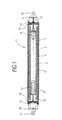
- an embodiment of a counter-die cylinder for a stamping machine for laminar material (not shown), indicated generally by reference 1, particularly suitable for stamping corrugated cardboard boxes, comprises an elongated cylindrical body (2) that rotates on its own axis and is horizontally coupled to the frame or bed of the stamping machine by means of two circular metal (9,10) plates at each end, which are each provided with axis-centred support and rotation (16, 17) respectively through which the rotational movement of the counter-die cylinder (1) is transmitted in a known way so it is not necessary to go into greater detail.
- a plurality of aligned tubular elements (3), arranged on the outer surface of the cylindrical body (2) and a plurality of shrouds (4) are provided, for example, polyurethane, each of which is arranged around its corresponding tubular element (3).
- the counter-die cylinder (1) is provided with movement means, which will be detailed hereinbelow, that allow movement, in a longitudinal direction, of the tubular elements (3) along with shrouds (4) with respect to the axis of the cylindrical body (2), such that the position of the tubular element (3) can vary along the length of the cylindrical body (2) by a relatively slow swinging movement of the shroud, i.e., from one end of the machine bed to the other on which the counter-die cylinder (1) is arranged, with said movement means actuated by automated actuation means which can be actuated by means of a button located on a part of the stamping machine or connected to the actual functioning of the counter-die cylinder (1).
- such movement means comprise a pusher element (5) associated with automated actuation means and a counter-pressure element (6) capable of being moved that exerts a force opposite to the force exerted by the pusher element (5).
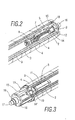
- this comprises a pusher member located on an axially movable axis (7) that passes through the inner cavity of the cylindrical body (2) that is provided with a reduced size geared motor (8), with dual rotation direction while the pusher member is in direct contact with a buffer ring (12) arranged at one end of the tubular element (3).
- the counter-pressure element (6) comprises a pneumatic cylinder (11), connected to a supply of compressed air that may be associated with other parts of the stamping machine, whose pneumatic cylinder (11) is housed inside the cylindrical body (2) and is integrally secured on the inside thereof.
- Said counter-pressure element (6) includes a pusher member movable by means of the cylinder (11) piston (19), which is in contact with a second buffer ring (13) arranged at the end opposite to the previously mentioned end. While the counter-die cylinder (1) is operating, this pneumatic cylinder (11) exerts a constant pressure on the buffer ring (13) that can be adjusted if so required.
- the axis (7) always works against the force exerted by the pneumatic cylinder (11) and is responsible for transmitting the final movement of the shrouds.
- the changing rotating direction of the axis (7) can be carried out using detector elements or limit switches located on both the outside and inside of the counter-die cylinder (1).
- the two aforementioned pusher members each comprise an annular body (14), 14' respectively, provided with retention tabs (15, 15') that protrude radially outwards and movable along raglets (18) located in the cylindrical body (2) in a radial arrangement, with the number of raglets (18) equal to the number of retention tabs provided.
- retention tabs (15, 15') consist of metal plates that have a protuberance on the upper part that acts as a buffer with a flange on the buffer ring.
- Figure 4 shows a sequence of three stages where the movement of the shrouds (4) to the left of the image can be seen, such that the buffer rings (12 and 13) move together with the shrouds (4) by means of the retention tabs (15, 15'). Additionally, this figure shows the arrangement of the die-holder cylinder above the counter-die cylinder (1) described in the memory herein.
- the movement means and motorized actuation means may be located outside the cylindrical body, which have used the same reference numerals for the common elements with the previously described embodiment.
- the movement means of the counter-die cylinder comprise a pair of pins (20), (21) each associated to respective buffer rings (12), (13) located at the two opposite ends of the counter-die cylinder (1), performing the swinging movement of such pins (20), (21) in a similar manner to the pusher members described previously along a spindle (22) which runs in parallel and separately to the counter-die cylinder, as indicated by arrows in Figure 5 .
- each of the pins is provided with a geared actuation system (23), (24) respectively which is integral to the corresponding pin (20), (21).
- buffer rings (12), (13) may have an additional incorporated mechanism that rotates with the tubular elements on which the shrouds are, preventing wear as a result of friction during movement.
- cylindrical body/bodies and shroud(s) can form a single integral body axially moveable without thereby departing from the scope of protection defined by the characteristics in claim 1.
Landscapes
- Life Sciences & Earth Sciences (AREA)
- Forests & Forestry (AREA)
- Engineering & Computer Science (AREA)
- Mechanical Engineering (AREA)
- Perforating, Stamping-Out Or Severing By Means Other Than Cutting (AREA)
- Details Of Cutting Devices (AREA)
- Actuator (AREA)
Claims (14)
- Cylindre contre-matrice (1) pour une machine à estamper en matériau laminaire qui comprend un corps cylindrique (2) tournant sur son propre axe, au moins un élément tubulaire (3), délimitant deux extrémités opposées, disposé sur le corps cylindrique (2) et au moins un protecteur (4) disposé autour dudit élément tubulaire correspondant (3), caractérisé en ce qu'il comprend des moyens de déplacement reliés aux deux extrémités opposées et composés au moins d'un élément tubulaire pour déplacer dans le sens longitudinal par rapport à l'axe du corps cylindrique ledit élément tubulaire, de telle manière que la position de l'élément tubulaire peut varier le long du corps cylindrique (2), ces moyens de déplacement étant actionnés par des moyens d'actionnement automatisés.
- Cylindre contre-matrice (1) selon la revendication 1, caractérisé en ce que les moyens de déplacement et les moyens d'actionnement automatisés sont placés à l'intérieur du corps cylindrique (2).
- Cylindre contre-matrice (1) selon la revendication 1, caractérisé en ce que les moyens de déplacement et les moyens d'actionnement automatisés sont placés à l'extérieur du corps cylindrique (2).
- Cylindre contre-matrice (1) selon la revendication 2 ou 3, caractérisé en ce que les moyens de déplacement comprennent au moins un élément de poussée associé aux moyens d'actionnement automatisés.
- Cylindre contre-matrice (1) selon la revendication 4, caractérisé en ce qu'il comprend un élément de contre-pression qui exerce une force opposée à la force exercée par l'élément de poussée.
- Cylindre contre-matrice (1) selon la revendication 1, caractérisé en ce que, à chacune des extrémités qui englobent la longueur totale définie par au moins un élément tubulaire, il dispose d'un anneau de butée (12, 13).
- Cylindre contre-matrice (1) selon la revendication 2, 4 et 5 caractérisé en ce que l'élément de poussée comprend un membre pousseur placé sur un axe déplaçable axialement qui passe à l'intérieur du corps cylindrique (2) muni d'un moteur à double sens de rotation, le membre pousseur étant en contact direct avec l'un des anneaux de butée (12) disposé à une extrémité finale de l'élément tubulaire.
- Cylindre contre-matrice (1) selon la revendication 2, 5 et 6, caractérisé en ce que l'élément contre-pression comprend un cylindre pneumatique logé à l'intérieur du corps cylindrique (2) d'une manière fixe incluant un membre pousseur déplaçable qui est en contact direct avec le second anneau de butée (13) disposé à l'extrémité finale opposée à l'extrémité finale antérieure.
- Cylindre contre-matrice (1) selon la revendication 7, caractérisé en ce que le membre pousseur comprend un corps annulaire muni d'au moins une languette de retenue en saillie vers l'extérieur et déplaçable le long d'une cannelure placée dans le corps cylindrique, le corps annulaire étant fixé de manière solidaire à une broche raccordée au moteur.
- Cylindre contre-matrice (1) selon la revendication 8, caractérisé en ce que le membre pousseur comprend un corps annulaire muni d'au moins une languette de retenue qui forme une saillie vers l'extérieur et déplaçable le long d'une cannelure placée dans le corps cylindrique, le corps annulaire étant fixé de manière solidaire à un piston déplaçable qui fait partie du cylindre pneumatique.
- Cylindre contre-matrice (1) selon la revendication 1, caractérisé en ce qu'il comprend une pluralité d'éléments tubulaires alignés sur le corps cylindrique (2) rotatif, sur lesquels est placé le protecteur correspondant (4) sur chaque élément tubulaire (3).
- Cylindre contre-matrice (1) selon la revendication 1, caractérisé en ce que le corps cylindrique (2) est muni d'au moins une trappe de visite pour accéder à l'intérieur de celui-ci.
- Cylindre contre-matrice (1) selon la revendication 1, caractérisé en ce que la vitesse des moyens d'actionnement automatisés est régulable.
- Cylindre contre-matrice (1) selon la revendication 1, caractérisé en ce qu'il comprend des moyens de synchronisation, de manière que la vitesse linéaire des moyens de déplacement est synchronisée avec la vitesse rotative du corps cylindrique rotatif.
Applications Claiming Priority (2)
| Application Number | Priority Date | Filing Date | Title |
|---|---|---|---|
| ES200900921A ES2357123B1 (es) | 2009-04-03 | 2009-04-03 | Cilindro contra-troquel para una maquina troqueladora |
| PCT/ES2010/070071 WO2010112642A1 (fr) | 2009-04-03 | 2010-02-09 | Cylindre contre-poinçon pour poinçonneuse |
Publications (3)
| Publication Number | Publication Date |
|---|---|
| EP2415568A1 EP2415568A1 (fr) | 2012-02-08 |
| EP2415568A4 EP2415568A4 (fr) | 2013-01-02 |
| EP2415568B1 true EP2415568B1 (fr) | 2013-08-28 |
Family
ID=42827506
Family Applications (1)
| Application Number | Title | Priority Date | Filing Date |
|---|---|---|---|
| EP20100758089 Not-in-force EP2415568B1 (fr) | 2009-04-03 | 2010-02-09 | Cylindre contre-poinçon pour poinçonneuse |
Country Status (8)
| Country | Link |
|---|---|
| US (1) | US8528454B2 (fr) |
| EP (1) | EP2415568B1 (fr) |
| JP (1) | JP2012522650A (fr) |
| CN (1) | CN102378671A (fr) |
| BR (1) | BRPI1006786A2 (fr) |
| ES (1) | ES2357123B1 (fr) |
| MX (1) | MX2011010232A (fr) |
| WO (1) | WO2010112642A1 (fr) |
Family Cites Families (11)
| Publication number | Priority date | Publication date | Assignee | Title |
|---|---|---|---|---|
| US3882745A (en) * | 1972-12-29 | 1975-05-13 | Koppers Co Inc | Method and apparatus for accurate die-cutting |
| US3916744A (en) * | 1973-05-02 | 1975-11-04 | Henry L West | Rotary web perforating apparatus |
| US4063493A (en) * | 1976-11-15 | 1977-12-20 | H&H Industries, Inc. | Rotary die cutting machine |
| US4240312A (en) * | 1979-05-15 | 1980-12-23 | The Ward Machinery Company | Apparatus for improving wear life of rotary die cutter anvil covers |
| US4736660A (en) * | 1986-05-21 | 1988-04-12 | The Ward Machinery Company | Rotary die-cut apparatus and gearing arrangement therein |
| US6135002A (en) * | 1998-04-27 | 2000-10-24 | Neal; Kenneth Ray | Die cutter blanket and bearing and method of arranging the blanket and bearing on an anvil |
| US6609997B1 (en) * | 1999-12-23 | 2003-08-26 | Sun Automation Inc. | Method and apparatus for resurfacing anvil blanket of a rotary diecutter for box making machine |
| DE10148503C5 (de) * | 2001-10-01 | 2008-01-31 | Koenig & Bauer Aktiengesellschaft | Falzapparat mit umfangsverstellbarem Zylinder |
| US6991696B2 (en) * | 2003-03-21 | 2006-01-31 | Kimberly-Clark Worldwide, Inc. | Method of forming a disposable, refastenable absorbent article |
| WO2005118238A1 (fr) * | 2004-05-26 | 2005-12-15 | Bhs Corrugated Maschinen Und Anlagenbau Gmbh | Balai rotatif |
| WO2009113900A1 (fr) * | 2008-03-12 | 2009-09-17 | Kizyma Aleksandr Alekseevich | Machine rotative universelle de fabrication de patrons pour articles de cartonnage |
-
2009
- 2009-04-03 ES ES200900921A patent/ES2357123B1/es not_active Expired - Fee Related
-
2010
- 2010-02-09 JP JP2012502720A patent/JP2012522650A/ja not_active Withdrawn
- 2010-02-09 EP EP20100758089 patent/EP2415568B1/fr not_active Not-in-force
- 2010-02-09 MX MX2011010232A patent/MX2011010232A/es not_active Application Discontinuation
- 2010-02-09 US US13/262,649 patent/US8528454B2/en not_active Expired - Fee Related
- 2010-02-09 WO PCT/ES2010/070071 patent/WO2010112642A1/fr not_active Ceased
- 2010-02-09 BR BRPI1006786A patent/BRPI1006786A2/pt not_active IP Right Cessation
- 2010-02-09 CN CN2010800145918A patent/CN102378671A/zh active Pending
Also Published As
| Publication number | Publication date |
|---|---|
| US8528454B2 (en) | 2013-09-10 |
| EP2415568A4 (fr) | 2013-01-02 |
| MX2011010232A (es) | 2011-10-11 |
| ES2357123B1 (es) | 2012-05-25 |
| CN102378671A (zh) | 2012-03-14 |
| WO2010112642A1 (fr) | 2010-10-07 |
| EP2415568A1 (fr) | 2012-02-08 |
| BRPI1006786A2 (pt) | 2016-03-15 |
| ES2357123A1 (es) | 2011-04-19 |
| JP2012522650A (ja) | 2012-09-27 |
| US20120048091A1 (en) | 2012-03-01 |
Similar Documents
| Publication | Publication Date | Title |
|---|---|---|
| US5297464A (en) | Rotary shears | |
| US8495938B2 (en) | Displacement unit | |
| JP6559664B2 (ja) | 工具機械のためのターレット | |
| US3783780A (en) | Intaglio print machine with novel roll mounting mandrel and bushing assembly | |
| AU2006217120B2 (en) | A cutting-and creasing-wheel assembly, and a method for cutting and creasing a compressible material | |
| CA2466330A1 (fr) | Machine a decouper des feuillards a commande numerique par ordinateur | |
| CN102310429B (zh) | 用于旋转冲压扁平多层物品的设备 | |
| EP1845048B1 (fr) | Ensemble de pliage et de découpe pour des produits tels que les tissus, les serviettes ou similaires | |
| CN111032298A (zh) | 用于切割刀片的研磨单元、包括所述单元的机器及相关方法 | |
| US4718265A (en) | Bending apparatus for rod- or ribbon-shaped material | |
| CN110382149B (zh) | 刀具头和带有刀具头的刀具系统 | |
| EP2415568B1 (fr) | Cylindre contre-poinçon pour poinçonneuse | |
| EP1612009B1 (fr) | Système d'admission d'air et appareil de découpe rotatif avec un tel système | |
| US8707840B2 (en) | Apparatus for slicing food products | |
| US6869388B2 (en) | Folding blade cylinder of a folding machine | |
| JP6599590B2 (ja) | カバーベアリングシステム | |
| US20110120283A1 (en) | Counter-Die Cylinder for a Machine for Stamping Sheet-Like Material and Method for Mounting/Removing a Cover | |
| JP6683705B2 (ja) | 軸受、平坦基材変換ユニット、回転工具の取付け及び取外しのための方法 | |
| GB2195935A (en) | Rotary cutting apparatus for tubes | |
| JP4086294B2 (ja) | 巻取物の切断装置 | |
| JPH0259295A (ja) | スリッタ装置 | |
| WO2018024335A1 (fr) | Bobineuse à broches en mosaïque extensibles | |
| IT202300021459A1 (it) | Sistema di fissaggio di fustelle rotanti in macchine per la fustellatura di materiale laminare | |
| ITUD990095A1 (it) | Dispositivo di affilatura per lame a disco | |
| ITMI962218A1 (it) | Apparecchiatura per il taglio in continuo a misura di materiale profilato cavo |
Legal Events
| Date | Code | Title | Description |
|---|---|---|---|
| PUAI | Public reference made under article 153(3) epc to a published international application that has entered the european phase |
Free format text: ORIGINAL CODE: 0009012 |
|
| 17P | Request for examination filed |
Effective date: 20110923 |
|
| AK | Designated contracting states |
Kind code of ref document: A1 Designated state(s): AT BE BG CH CY CZ DE DK EE ES FI FR GB GR HR HU IE IS IT LI LT LU LV MC MK MT NL NO PL PT RO SE SI SK SM TR |
|
| DAX | Request for extension of the european patent (deleted) | ||
| A4 | Supplementary search report drawn up and despatched |
Effective date: 20121205 |
|
| RIC1 | Information provided on ipc code assigned before grant |
Ipc: B26D 3/18 20060101ALI20121129BHEP Ipc: B26D 7/26 20060101ALI20121129BHEP Ipc: B26D 7/20 20060101AFI20121129BHEP |
|
| GRAP | Despatch of communication of intention to grant a patent |
Free format text: ORIGINAL CODE: EPIDOSNIGR1 |
|
| RIC1 | Information provided on ipc code assigned before grant |
Ipc: B26D 7/26 20060101ALI20130221BHEP Ipc: B26D 3/18 20060101ALI20130221BHEP Ipc: B26D 7/20 20060101AFI20130221BHEP |
|
| GRAS | Grant fee paid |
Free format text: ORIGINAL CODE: EPIDOSNIGR3 |
|
| GRAA | (expected) grant |
Free format text: ORIGINAL CODE: 0009210 |
|
| AK | Designated contracting states |
Kind code of ref document: B1 Designated state(s): AT BE BG CH CY CZ DE DK EE ES FI FR GB GR HR HU IE IS IT LI LT LU LV MC MK MT NL NO PL PT RO SE SI SK SM TR |
|
| REG | Reference to a national code |
Ref country code: GB Ref legal event code: FG4D |
|
| REG | Reference to a national code |
Ref country code: CH Ref legal event code: EP |
|
| REG | Reference to a national code |
Ref country code: AT Ref legal event code: REF Ref document number: 629026 Country of ref document: AT Kind code of ref document: T Effective date: 20130915 |
|
| REG | Reference to a national code |
Ref country code: IE Ref legal event code: FG4D |
|
| REG | Reference to a national code |
Ref country code: DE Ref legal event code: R096 Ref document number: 602010009834 Country of ref document: DE Effective date: 20131024 |
|
| REG | Reference to a national code |
Ref country code: AT Ref legal event code: MK05 Ref document number: 629026 Country of ref document: AT Kind code of ref document: T Effective date: 20130828 |
|
| REG | Reference to a national code |
Ref country code: LT Ref legal event code: MG4D |
|
| REG | Reference to a national code |
Ref country code: NL Ref legal event code: VDEP Effective date: 20130828 |
|
| PG25 | Lapsed in a contracting state [announced via postgrant information from national office to epo] |
Ref country code: NO Free format text: LAPSE BECAUSE OF FAILURE TO SUBMIT A TRANSLATION OF THE DESCRIPTION OR TO PAY THE FEE WITHIN THE PRESCRIBED TIME-LIMIT Effective date: 20131128 Ref country code: HR Free format text: LAPSE BECAUSE OF FAILURE TO SUBMIT A TRANSLATION OF THE DESCRIPTION OR TO PAY THE FEE WITHIN THE PRESCRIBED TIME-LIMIT Effective date: 20130828 Ref country code: LT Free format text: LAPSE BECAUSE OF FAILURE TO SUBMIT A TRANSLATION OF THE DESCRIPTION OR TO PAY THE FEE WITHIN THE PRESCRIBED TIME-LIMIT Effective date: 20130828 Ref country code: CY Free format text: LAPSE BECAUSE OF FAILURE TO SUBMIT A TRANSLATION OF THE DESCRIPTION OR TO PAY THE FEE WITHIN THE PRESCRIBED TIME-LIMIT Effective date: 20130807 Ref country code: PT Free format text: LAPSE BECAUSE OF FAILURE TO SUBMIT A TRANSLATION OF THE DESCRIPTION OR TO PAY THE FEE WITHIN THE PRESCRIBED TIME-LIMIT Effective date: 20131230 Ref country code: AT Free format text: LAPSE BECAUSE OF FAILURE TO SUBMIT A TRANSLATION OF THE DESCRIPTION OR TO PAY THE FEE WITHIN THE PRESCRIBED TIME-LIMIT Effective date: 20130828 Ref country code: IS Free format text: LAPSE BECAUSE OF FAILURE TO SUBMIT A TRANSLATION OF THE DESCRIPTION OR TO PAY THE FEE WITHIN THE PRESCRIBED TIME-LIMIT Effective date: 20131228 Ref country code: SE Free format text: LAPSE BECAUSE OF FAILURE TO SUBMIT A TRANSLATION OF THE DESCRIPTION OR TO PAY THE FEE WITHIN THE PRESCRIBED TIME-LIMIT Effective date: 20130828 |
|
| REG | Reference to a national code |
Ref country code: NL Ref legal event code: VDEP Effective date: 20130828 |
|
| PG25 | Lapsed in a contracting state [announced via postgrant information from national office to epo] |
Ref country code: GR Free format text: LAPSE BECAUSE OF FAILURE TO SUBMIT A TRANSLATION OF THE DESCRIPTION OR TO PAY THE FEE WITHIN THE PRESCRIBED TIME-LIMIT Effective date: 20131129 Ref country code: SI Free format text: LAPSE BECAUSE OF FAILURE TO SUBMIT A TRANSLATION OF THE DESCRIPTION OR TO PAY THE FEE WITHIN THE PRESCRIBED TIME-LIMIT Effective date: 20130828 Ref country code: LV Free format text: LAPSE BECAUSE OF FAILURE TO SUBMIT A TRANSLATION OF THE DESCRIPTION OR TO PAY THE FEE WITHIN THE PRESCRIBED TIME-LIMIT Effective date: 20130828 Ref country code: PL Free format text: LAPSE BECAUSE OF FAILURE TO SUBMIT A TRANSLATION OF THE DESCRIPTION OR TO PAY THE FEE WITHIN THE PRESCRIBED TIME-LIMIT Effective date: 20130828 Ref country code: BE Free format text: LAPSE BECAUSE OF FAILURE TO SUBMIT A TRANSLATION OF THE DESCRIPTION OR TO PAY THE FEE WITHIN THE PRESCRIBED TIME-LIMIT Effective date: 20130828 Ref country code: FI Free format text: LAPSE BECAUSE OF FAILURE TO SUBMIT A TRANSLATION OF THE DESCRIPTION OR TO PAY THE FEE WITHIN THE PRESCRIBED TIME-LIMIT Effective date: 20130828 |
|
| PG25 | Lapsed in a contracting state [announced via postgrant information from national office to epo] |
Ref country code: CY Free format text: LAPSE BECAUSE OF FAILURE TO SUBMIT A TRANSLATION OF THE DESCRIPTION OR TO PAY THE FEE WITHIN THE PRESCRIBED TIME-LIMIT Effective date: 20130828 |
|
| PG25 | Lapsed in a contracting state [announced via postgrant information from national office to epo] |
Ref country code: EE Free format text: LAPSE BECAUSE OF FAILURE TO SUBMIT A TRANSLATION OF THE DESCRIPTION OR TO PAY THE FEE WITHIN THE PRESCRIBED TIME-LIMIT Effective date: 20130828 Ref country code: RO Free format text: LAPSE BECAUSE OF FAILURE TO SUBMIT A TRANSLATION OF THE DESCRIPTION OR TO PAY THE FEE WITHIN THE PRESCRIBED TIME-LIMIT Effective date: 20130828 Ref country code: NL Free format text: LAPSE BECAUSE OF FAILURE TO SUBMIT A TRANSLATION OF THE DESCRIPTION OR TO PAY THE FEE WITHIN THE PRESCRIBED TIME-LIMIT Effective date: 20130828 Ref country code: DK Free format text: LAPSE BECAUSE OF FAILURE TO SUBMIT A TRANSLATION OF THE DESCRIPTION OR TO PAY THE FEE WITHIN THE PRESCRIBED TIME-LIMIT Effective date: 20130828 Ref country code: SK Free format text: LAPSE BECAUSE OF FAILURE TO SUBMIT A TRANSLATION OF THE DESCRIPTION OR TO PAY THE FEE WITHIN THE PRESCRIBED TIME-LIMIT Effective date: 20130828 Ref country code: CZ Free format text: LAPSE BECAUSE OF FAILURE TO SUBMIT A TRANSLATION OF THE DESCRIPTION OR TO PAY THE FEE WITHIN THE PRESCRIBED TIME-LIMIT Effective date: 20130828 |
|
| PG25 | Lapsed in a contracting state [announced via postgrant information from national office to epo] |
Ref country code: ES Free format text: LAPSE BECAUSE OF FAILURE TO SUBMIT A TRANSLATION OF THE DESCRIPTION OR TO PAY THE FEE WITHIN THE PRESCRIBED TIME-LIMIT Effective date: 20130828 Ref country code: IT Free format text: LAPSE BECAUSE OF FAILURE TO SUBMIT A TRANSLATION OF THE DESCRIPTION OR TO PAY THE FEE WITHIN THE PRESCRIBED TIME-LIMIT Effective date: 20130828 |
|
| REG | Reference to a national code |
Ref country code: DE Ref legal event code: R097 Ref document number: 602010009834 Country of ref document: DE |
|
| PLBE | No opposition filed within time limit |
Free format text: ORIGINAL CODE: 0009261 |
|
| STAA | Information on the status of an ep patent application or granted ep patent |
Free format text: STATUS: NO OPPOSITION FILED WITHIN TIME LIMIT |
|
| 26N | No opposition filed |
Effective date: 20140530 |
|
| REG | Reference to a national code |
Ref country code: DE Ref legal event code: R119 Ref document number: 602010009834 Country of ref document: DE |
|
| REG | Reference to a national code |
Ref country code: DE Ref legal event code: R097 Ref document number: 602010009834 Country of ref document: DE Effective date: 20140530 |
|
| PG25 | Lapsed in a contracting state [announced via postgrant information from national office to epo] |
Ref country code: LU Free format text: LAPSE BECAUSE OF FAILURE TO SUBMIT A TRANSLATION OF THE DESCRIPTION OR TO PAY THE FEE WITHIN THE PRESCRIBED TIME-LIMIT Effective date: 20140209 Ref country code: MC Free format text: LAPSE BECAUSE OF FAILURE TO SUBMIT A TRANSLATION OF THE DESCRIPTION OR TO PAY THE FEE WITHIN THE PRESCRIBED TIME-LIMIT Effective date: 20130828 |
|
| REG | Reference to a national code |
Ref country code: CH Ref legal event code: PL |
|
| GBPC | Gb: european patent ceased through non-payment of renewal fee |
Effective date: 20140209 |
|
| PG25 | Lapsed in a contracting state [announced via postgrant information from national office to epo] |
Ref country code: LI Free format text: LAPSE BECAUSE OF NON-PAYMENT OF DUE FEES Effective date: 20140228 Ref country code: CH Free format text: LAPSE BECAUSE OF NON-PAYMENT OF DUE FEES Effective date: 20140228 |
|
| REG | Reference to a national code |
Ref country code: FR Ref legal event code: ST Effective date: 20141031 |
|
| REG | Reference to a national code |
Ref country code: DE Ref legal event code: R119 Ref document number: 602010009834 Country of ref document: DE Effective date: 20140902 |
|
| REG | Reference to a national code |
Ref country code: IE Ref legal event code: MM4A |
|
| PG25 | Lapsed in a contracting state [announced via postgrant information from national office to epo] |
Ref country code: IE Free format text: LAPSE BECAUSE OF NON-PAYMENT OF DUE FEES Effective date: 20140209 Ref country code: DE Free format text: LAPSE BECAUSE OF NON-PAYMENT OF DUE FEES Effective date: 20140902 Ref country code: GB Free format text: LAPSE BECAUSE OF NON-PAYMENT OF DUE FEES Effective date: 20140209 Ref country code: FR Free format text: LAPSE BECAUSE OF NON-PAYMENT OF DUE FEES Effective date: 20140228 |
|
| PG25 | Lapsed in a contracting state [announced via postgrant information from national office to epo] |
Ref country code: MT Free format text: LAPSE BECAUSE OF FAILURE TO SUBMIT A TRANSLATION OF THE DESCRIPTION OR TO PAY THE FEE WITHIN THE PRESCRIBED TIME-LIMIT Effective date: 20130828 |
|
| PG25 | Lapsed in a contracting state [announced via postgrant information from national office to epo] |
Ref country code: SM Free format text: LAPSE BECAUSE OF FAILURE TO SUBMIT A TRANSLATION OF THE DESCRIPTION OR TO PAY THE FEE WITHIN THE PRESCRIBED TIME-LIMIT Effective date: 20130828 |
|
| PG25 | Lapsed in a contracting state [announced via postgrant information from national office to epo] |
Ref country code: BG Free format text: LAPSE BECAUSE OF FAILURE TO SUBMIT A TRANSLATION OF THE DESCRIPTION OR TO PAY THE FEE WITHIN THE PRESCRIBED TIME-LIMIT Effective date: 20130828 |
|
| PG25 | Lapsed in a contracting state [announced via postgrant information from national office to epo] |
Ref country code: TR Free format text: LAPSE BECAUSE OF FAILURE TO SUBMIT A TRANSLATION OF THE DESCRIPTION OR TO PAY THE FEE WITHIN THE PRESCRIBED TIME-LIMIT Effective date: 20130828 Ref country code: HU Free format text: LAPSE BECAUSE OF FAILURE TO SUBMIT A TRANSLATION OF THE DESCRIPTION OR TO PAY THE FEE WITHIN THE PRESCRIBED TIME-LIMIT; INVALID AB INITIO Effective date: 20100209 |
|
| PG25 | Lapsed in a contracting state [announced via postgrant information from national office to epo] |
Ref country code: MK Free format text: LAPSE BECAUSE OF FAILURE TO SUBMIT A TRANSLATION OF THE DESCRIPTION OR TO PAY THE FEE WITHIN THE PRESCRIBED TIME-LIMIT Effective date: 20130828 |