EP2416082A1 - Wärmequellensystem und steuerverfahren dafür - Google Patents
Wärmequellensystem und steuerverfahren dafür Download PDFInfo
- Publication number
- EP2416082A1 EP2416082A1 EP10758621A EP10758621A EP2416082A1 EP 2416082 A1 EP2416082 A1 EP 2416082A1 EP 10758621 A EP10758621 A EP 10758621A EP 10758621 A EP10758621 A EP 10758621A EP 2416082 A1 EP2416082 A1 EP 2416082A1
- Authority
- EP
- European Patent Office
- Prior art keywords
- cooling
- centrifugal
- tower
- capacity
- chiller
- Prior art date
- Legal status (The legal status is an assumption and is not a legal conclusion. Google has not performed a legal analysis and makes no representation as to the accuracy of the status listed.)
- Withdrawn
Links
Images






Classifications
-
- F—MECHANICAL ENGINEERING; LIGHTING; HEATING; WEAPONS; BLASTING
- F25—REFRIGERATION OR COOLING; COMBINED HEATING AND REFRIGERATION SYSTEMS; HEAT PUMP SYSTEMS; MANUFACTURE OR STORAGE OF ICE; LIQUEFACTION SOLIDIFICATION OF GASES
- F25B—REFRIGERATION MACHINES, PLANTS OR SYSTEMS; COMBINED HEATING AND REFRIGERATION SYSTEMS; HEAT PUMP SYSTEMS
- F25B1/00—Compression machines, plants or systems with non-reversible cycle
- F25B1/04—Compression machines, plants or systems with non-reversible cycle with compressor of rotary type
- F25B1/053—Compression machines, plants or systems with non-reversible cycle with compressor of rotary type of turbine type
-
- F—MECHANICAL ENGINEERING; LIGHTING; HEATING; WEAPONS; BLASTING
- F25—REFRIGERATION OR COOLING; COMBINED HEATING AND REFRIGERATION SYSTEMS; HEAT PUMP SYSTEMS; MANUFACTURE OR STORAGE OF ICE; LIQUEFACTION SOLIDIFICATION OF GASES
- F25B—REFRIGERATION MACHINES, PLANTS OR SYSTEMS; COMBINED HEATING AND REFRIGERATION SYSTEMS; HEAT PUMP SYSTEMS
- F25B49/00—Arrangement or mounting of control or safety devices
- F25B49/02—Arrangement or mounting of control or safety devices for compression type machines, plants or systems
- F25B49/027—Condenser control arrangements
-
- F—MECHANICAL ENGINEERING; LIGHTING; HEATING; WEAPONS; BLASTING
- F28—HEAT EXCHANGE IN GENERAL
- F28B—STEAM OR VAPOUR CONDENSERS
- F28B9/00—Auxiliary systems, arrangements, or devices
- F28B9/04—Auxiliary systems, arrangements, or devices for feeding, collecting, and storing cooling water or other cooling liquid
- F28B9/06—Auxiliary systems, arrangements, or devices for feeding, collecting, and storing cooling water or other cooling liquid with provision for re-cooling the cooling water or other cooling liquid
-
- F—MECHANICAL ENGINEERING; LIGHTING; HEATING; WEAPONS; BLASTING
- F25—REFRIGERATION OR COOLING; COMBINED HEATING AND REFRIGERATION SYSTEMS; HEAT PUMP SYSTEMS; MANUFACTURE OR STORAGE OF ICE; LIQUEFACTION SOLIDIFICATION OF GASES
- F25B—REFRIGERATION MACHINES, PLANTS OR SYSTEMS; COMBINED HEATING AND REFRIGERATION SYSTEMS; HEAT PUMP SYSTEMS
- F25B2400/00—Component parts or details not otherwise provided for in this subclass
- F25B2400/06—Several compression cycles arranged in parallel
-
- F—MECHANICAL ENGINEERING; LIGHTING; HEATING; WEAPONS; BLASTING
- F25—REFRIGERATION OR COOLING; COMBINED HEATING AND REFRIGERATION SYSTEMS; HEAT PUMP SYSTEMS; MANUFACTURE OR STORAGE OF ICE; LIQUEFACTION SOLIDIFICATION OF GASES
- F25B—REFRIGERATION MACHINES, PLANTS OR SYSTEMS; COMBINED HEATING AND REFRIGERATION SYSTEMS; HEAT PUMP SYSTEMS
- F25B2700/00—Sensing or detecting of parameters; Sensors therefor
- F25B2700/21—Temperatures
- F25B2700/2106—Temperatures of fresh outdoor air
-
- F—MECHANICAL ENGINEERING; LIGHTING; HEATING; WEAPONS; BLASTING
- F28—HEAT EXCHANGE IN GENERAL
- F28C—HEAT-EXCHANGE APPARATUS, NOT PROVIDED FOR IN ANOTHER SUBCLASS, IN WHICH THE HEAT-EXCHANGE MEDIA COME INTO DIRECT CONTACT WITHOUT CHEMICAL INTERACTION
- F28C1/00—Direct-contact trickle coolers, e.g. cooling towers
- F28C2001/006—Systems comprising cooling towers, e.g. for recooling a cooling medium
-
- F—MECHANICAL ENGINEERING; LIGHTING; HEATING; WEAPONS; BLASTING
- F28—HEAT EXCHANGE IN GENERAL
- F28F—DETAILS OF HEAT-EXCHANGE AND HEAT-TRANSFER APPARATUS, OF GENERAL APPLICATION
- F28F27/00—Control arrangements or safety devices specially adapted for heat-exchange or heat-transfer apparatus
Definitions
- the present invention relates to a heat-source system and a method for controlling the same for improving the efficiency of the overall heat-source system.
- a known heat-source system used to supply chilled water and provide local heating and cooling in semiconductor factories includes a plurality of centrifugal-chillers that can be activated or deactivated according to the quantity of heat required by an external load.
- the heat-source system includes, besides the centrifugal-chillers, cooling-water pumps for supplying cooling water to condensers of the centrifugal-chillers, cooling towers for cooling the cooling water heated by recovering heat of condensation in the condensers by bringing the cooling water into contact with the outside air, and chilled-water pumps for supplying the chilled water cooled by evaporators of the centrifugal-chillers to the external load.
- the cooling towers have cooling-tower fans for introducing the outside air into the cooling towers.
- PTL 1 discloses an invention related to such a heat-source system, for improving the operating efficiency of the overall heat-source system, taking into consideration not only the chillers alone, but also auxiliary machines, such as the cooling-water pumps, the cooling towers, and the chilled-water pumps. More specifically, a table is formed, with which the COP of the overall heat-source system can be understood from the relationship between the outside-air wet-bulb temperature and the chiller load factor. Next, parameters used in an arithmetic expression which maximizes the COP of the overall heat-source system is determined from the table. Then, based on the result of calculation, the number and output powers of chillers to be operated and the flow rate and temperature of the cooling water are controlled.
- the heat-source system disclosed in PTL 1 is supposed to have a configuration in which the respective cooling towers are independently connected to the respective chillers, as shown in FIG. 1 therein.
- a heat-source system including a plurality of cooling towers that are commonly connected to respective centrifugal-chillers.
- a plurality of cooling towers can be activated so that the cooling-tower capacity is greater than the capacity corresponding to the centrifugal-chillers being operated. Assuming that, for example, only one centrifugal-chiller is operated.
- the cooling capacity increases. As a result, the temperature of the cooling water drops. If the temperature of the cooling water drops, the power consumption of the centrifugal-chiller may decrease, which may increase the efficiency.
- the power consumption of the cooling-tower fans increases, which may decrease the efficiency of the overall heat-source system.
- an increase in the power consumption of the cooling-tower fans may be relatively small, decreasing the power consumption of the centrifugal-chiller, which may increase the efficiency of the overall heat-source system.
- the efficiency of the overall heat-source system can be improved by selecting an appropriate number of cooling towers to be activated.
- the present invention has been made in view of the above-described circumstances, and an object thereof is to provide a heat-source system and a method for controlling the same in which the efficiency of the overall heat-source system can be improved by selecting an appropriate number of cooling towers to be activated.
- a heat-source system includes a centrifugal-chiller having a centrifugal-compressor driven by electricity and having a variable rotational frequency, the centrifugal-compressor compressing refrigerant gas, a condenser that condenses the refrigerant gas compressed by the centrifugal-compressor into liquid, an expansion valve that expands the refrigerant condensed into liquid by the condenser, and an evaporator that evaporates the refrigerant expanded by the expansion valve; a cooling-water pump driven by electricity that supplies cooling water for cooling the refrigerant by heat exchange in the condenser; a cooling tower that cools the cooling water guided from the condenser by the cooling-water pump by bringing the cooling water into contact with the outside air to perform heat exchange; a cooling-tower fan driven by electricity and
- a plurality of the centrifugal-chillers are provided.
- a plurality of the cooling towers are provided so as to have a cooling-tower capacity corresponding to the total capacity of the rated capacities of the respective centrifugal-chillers, the cooling towers being commonly connected to the plurality of centrifugal-chillers.
- the control unit can change the number of cooling towers to be operated so that the cooling-tower capacity can be changed.
- the control unit preliminarily stores an optimum cooling-tower capacity relationship representing the cooling-tower capacity of the cooling towers with which the heat-source system efficiency, taking into consideration the centrifugal-chillers, the cooling-water pump, the cooling towers, the cooling-tower fan, and the chilled-water pump, is higher, in relation to the outside-air wet-bulb temperature and the centrifugal-chiller partial load factor.
- the control unit determines the number of cooling towers to be operated by referring to the optimum cooling-tower capacity relationship, on the basis of the outside-air wet-bulb temperature and the partial load factor of the centrifugal-chillers during operation.
- cooling towers having a cooling capacity larger than the rated capacity of one centrifugal-chiller can be activated. For example, this state can be realized by operating a plurality of cooling towers while only one centrifugal-chiller is operated. Because the temperature of the cooling water decreases in this state, the power consumption of the centrifugal-chiller may decrease.
- many cooling-tower fans are activated, which may increase the power consumption of the cooling-tower fans.
- the efficiency of the overall heat-source system taking into consideration the centrifugal-chillers, the cooling-water pumps, the cooling towers, the cooling-tower fans, and the chilled-water pumps, is higher.
- the inventor found that there is a cooling-tower capacity of the cooling towers (for example, the number of cooling towers to be activated) with which the heat-source system efficiency is increased, which depends on the outside-air wet-bulb temperature and the centrifugal-chiller partial load factor.
- the cooling-tower capacity with which the efficiency of the heat-source system is increased is obtained in advance, in relation to the outside-air wet-bulb temperature and the centrifugal-chiller partial load factor, and operation is performed accordingly.
- the number of cooling towers to be operated can be determined simply by obtaining the outside-air wet-bulb temperature and the centrifugal-chiller partial load factor, extremely simple operation control can be realized.
- a moisture sensor is preferably used to obtain the outside-air wet-bulb temperature.
- the outside-air wet-bulb temperature may be obtained from the dry-bulb temperature, the relative humidity, and the outside pressure, instead of the moisture sensor.
- control unit may determine the number of cooling towers to be operated based on the optimum cooling-tower capacity relationship, such that a first capacity that is larger than the rated capacity of the operating centrifugal-chiller is provided, when the outside-air wet-bulb temperature is equal to or lower than a first predetermined temperature.
- the efficiency of the overall heat-source system is increased by determining the number of cooling towers to be operated such that the cooling-tower capacity is the first capacity, which is larger than the rated capacity of the operating centrifugal-chiller, when the outside-air wet-bulb temperature is equal to or lower than the first predetermined temperature. Accordingly, high-efficiency operation is realized by performing the above-described heat-source system operation during the winter period and an intermediate period when the outside-air wet-bulb temperature is low.
- the number of cooling towers to be operated can be determined based only on the outside-air wet-bulb temperature, independently of the centrifugal-chiller partial load factor. Accordingly, simple operation control is realized.
- control unit may determine the number of cooling towers to be operated such that an equal capacity, which is equal to the rated capacity of the operating centrifugal-chiller, is provided, when the outside-air wet-bulb temperature is higher than a second predetermined temperature and the centrifugal-chiller partial load factor is equal to or lower than a predetermined load factor.
- the efficiency of the overall heat-source system is increased by determining the number of cooling towers to be operated such that the capacity is equal to the rated capacity of the operating centrifugal-chiller, when the outside-air wet-bulb temperature is higher than the second predetermined temperature and the centrifugal-chiller partial load factor is equal to or lower than the predetermined load factor. Accordingly, high-efficiency operation is realized by performing the above-described heat-source system operation during an intermediate period when the outside-air wet-bulb temperature is relatively high and the quantity of heat required by the external load is small.
- the "second predetermined temperature" of the above-described configuration is set to the same value as the "first predetermined temperature", which is used as the threshold when the number of cooling towers to be operated is determined so as to provide the first capacity, it is only necessary to change the number of cooling towers using this predetermined temperature as the threshold. Accordingly, simplified operation control is realized.
- control unit may determine the number of cooling towers to be operated such that a second capacity, which is equal to or lower than the first capacity and is equal to or higher than the equal capacity, is provided, when the outside-air wet-bulb temperature is equal to or higher than the second predetermined temperature and the centrifugal-chiller partial load factor is equal to or higher than the predetermined load factor.
- the efficiency of the overall heat-source system is increased by determining the number of cooling towers to be operated such that the capacity is equal to or lower than the first capacity and is equal to or higher than the equal capacity, when the outside-air wet-bulb temperature is equal to or higher than the second predetermined temperature and the centrifugal-chiller partial load factor is equal to or higher than the predetermined load factor. Accordingly, high-efficiency operation is realized by performing the above-described heat-source system operation during the summer period when the outside-air wet-bulb temperature is relatively high and the quantity of heat required by the external load is large.
- control unit may control the flow rate of the cooling-water pump based on the centrifugal-chiller partial load factor, regardless of the outside-air wet-bulb temperature or the number of cooling towers to be operated.
- the flow rate of the cooling-water pumps decreases, the power consumption thereof decreases. Thus, it is expected that the efficiency improves. Conversely, it may be considered that the power consumption of the centrifugal-chiller increases, because the temperature of the cooling water increases.
- the inventor found that, as a result of a study of the cooling-water flow rate relative to the efficiency of the overall heat-source system, it was found that it is not heavily dependent on the outside-air wet-bulb temperature or the number of cooling towers to be operated, but is heavily dependent on the centrifugal-chiller partial load factor. Therefore, the flow rate of the cooling-water pumps is controlled based on the centrifugal-chiller partial load factor, not the outside-air wet-bulb temperature or the number of cooling towers to be operated. Thus, simplified operation control is realized. Furthermore, by combining this control with the above-described configurations in which the number of cooling towers to be operated is optimized from the standpoint of the efficiency, the heat-source system can be operated at an even higher efficiency.
- a method for controlling a heat-source system includes a centrifugal-chiller having a centrifugal-compressor driven by electricity and having a variable rotational frequency, the centrifugal-compressor compressing refrigerant, a condenser that condenses the refrigerant compressed by the centrifugal-compressor into liquid, an expansion valve that expands the refrigerant condensed into liquid by the condenser, and an evaporator that evaporates the refrigerant expanded by the expansion valve; a cooling-water pump driven by electricity that supplies cooling water for cooling the refrigerant by heat exchange in the condenser; a cooling tower that cools the cooling water guided from the condenser by the cooling-water pump by bringing the cooling water into contact with the outside air to perform heat exchange; a cooling-tower fan driven by electricity and provided on the cooling tower, the cooling-tower fan introducing the outside air into the cooling tower; a chilled-water pump driven by
- a plurality of the centrifugal-chillers are provided.
- a plurality of the cooling towers are provided so as to have a cooling-tower capacity corresponding to the total capacity of the rated capacities of the respective centrifugal-chillers, the cooling towers being commonly connected to the plurality of centrifugal-chillers.
- the control unit can change the number of cooling towers to be operated so that the cooling-tower capacity can be changed.
- the control unit preliminarily stores an optimum cooling-tower capacity relationship representing the cooling-tower capacity of the cooling towers with which the heat-source system efficiency, taking into consideration the centrifugal-chillers, the cooling-water pump, the cooling towers, the cooling-tower fan, and the chilled-water pump, is higher, in relation to the outside-air wet-bulb temperature and the centrifugal-chiller partial load factor.
- the control unit determines the number of cooling towers to be operated by referring to the optimum cooling-tower capacity relationship, on the basis of the outside-air wet-bulb temperature and the partial load factor of the centrifugal-chillers during operation.
- cooling towers having a cooling capacity larger than the rated capacity of one centrifugal-chiller can be activated. For example, this state can be realized by operating a plurality of cooling towers while only one centrifugal-chiller is operated. Because the temperature of the cooling water decreases in this state, the power consumption of the centrifugal-chiller may decrease.
- many cooling-tower fans are activated, which may increase the power consumption of the cooling-tower fans.
- the efficiency of the overall heat-source system taking into consideration the centrifugal-chillers, the cooling-water pumps, the cooling towers, the cooling-tower fans, and the chilled-water pumps, is higher.
- the inventor found that there is a cooling-tower capacity of the cooling towers (for example, the number of cooling towers to be activated) with which the heat-source system efficiency is increased, which depends on the outside-air wet-bulb temperature and the centrifugal-chiller partial load factor.
- the cooling-tower capacity with which the efficiency of the heat-source system is increased is obtained in advance, in relation to the outside-air wet-bulb temperature and the centrifugal-chiller partial load factor, and operation is performed accordingly.
- the number of cooling towers to be operated can be determined simply by obtaining the outside-air wet-bulb temperature and the centrifugal-chiller partial load factor, extremely simple operation control can be realized.
- a moisture sensor is preferably used to obtain the outside-air wet-bulb temperature.
- the outside-air wet-bulb temperature may be obtained from the dry-bulb temperature, the relative humidity, and the outside pressure, instead of the moisture sensor.
- the heat-source system and the method for controlling the same according to the present invention provide the following advantages.
- the number of cooling towers to be operated is determined based on the relationship that shows the cooling-tower capacity of the cooling tower with which the efficiency of the overall heat-source system is higher, with respect to the outside-air wet-bulb temperature and the centrifugal-chiller partial load factor. Accordingly, an efficient operation of the heat-source system can be achieved by extremely simple operation control. Furthermore, by reducing the cooling-water flow rate, a more efficient operation of the heat-source system can be achieved.
- FIG. 1 shows a heat-source system according to an embodiment of the present invention.
- a heat-source system 1 includes a plurality of (six, in this embodiment) centrifugal-chillers 3 arranged in parallel and a plurality of (six, in this embodiment) cooling towers 5 arranged in parallel.
- the centrifugal-chillers 3 each include a centrifugal-compressor 7 that compresses refrigerant, a condenser 9 that condenses the refrigerant compressed by the centrifugal-compressor 7 into liquid, an expansion valve (not shown) that expands the refrigerant condensed into liquid by the condenser 9, and an evaporator 11 that evaporates the refrigerant expanded by the expansion valve.
- the centrifugal-compressor 7 is driven by an electric motor 13 whose rotational frequency can be varied by an inverter device.
- Cooling water supplied by cooling-water pumps 15 is guided to the condenser 9.
- two cooling-water pumps 15 arranged in parallel are used, each being driven by an electric motor (not shown) whose rotational frequency can be varied by an inverter device and having a cooling-water-pump switching valve (not shown) that is opened or closed when only one of the cooling-water pumps 15 is operated.
- one of the cooling-water pumps 15 may be operated at a fixed rate and only the other one may be operated at a variable rate by driving it with an inverter.
- Each cooling-water pump 15 takes in cooling water guided from a cooling-water inflow header 17 and discharges the cooling water to the condenser 9 side.
- the cooling water discharged from the condenser 9 side is guided to a cooling-water outflow header 19. All the centrifugal-chillers 3 and all the cooling towers 5 are commonly connected to the cooling-water inflow header 17. All the centrifugal-chillers 3 and all the cooling towers 5 are also commonly connected to the cooling-water outflow header 19.
- Chilled water supplied by chilled-water pumps 21 is guided to the evaporator 11.
- two chilled-water pumps 21 arranged in parallel are used, each being driven by an electric motor (not shown) whose rotational frequency can be varied by an inverter device and having a chilled-water-pump switching valve (not shown) that is opened or closed when only one of the chilled-water pumps 21 is operated.
- one of the chilled-water pumps 21 may be operated at a fixed rate and only the other one may be operated at a variable rate by driving it with an inverter.
- Each chilled-water pump 21 takes in guided chilled water from a chilled-water inflow header 23 and discharges the chilled water to the evaporator 11 side.
- the chilled water discharged from the evaporator 11 side is guided to a chilled-water outflow header 25.
- All the centrifugal-chillers 3 are commonly connected to the chilled-water inflow header 23. All the centrifugal-chillers 3 are also commonly connected to the chilled-water outflow header 25.
- the chilled-water inflow header 23 and the chilled-water outflow header 25 are connected to an external load (not shown). Chilled water (at a temperature of, for example, 7°C) cooled by the evaporator 11 is supplied to the external load via the chilled-water outflow header 25, and the chilled water (at a temperature of, for example, 12°C) used and heated by the external load is returned to the evaporator 11 side via the chilled-water inflow header 23.
- the cooling tower 5 includes a cooling-tower fan 30, a sprinkler header 32, and a cooling-water reservoir tank 34.
- the cooling-tower fan 30 is used to introduce the outside air into the cooling tower 5 and is driven by an electric motor 36.
- An electric motor whose rotational frequency can be varied by an inverter device may be suitably used as this electric motor 36.
- a sprinkler header 32 sprays cooling water from above, allowing the cooling water to flow down a filler (not shown), which has a large surface area and is disposed below the sprinkler header 32, so that the cooling water comes into contact with the outside air, thereby cooling the cooling water utilizing not only sensible heat, but also latent heat of vaporization.
- a cooling-water outflow on-off valve 38 is provided between the sprinkler header 32 and the cooling-water outflow header 19. Cooled cooling water, which has been sprayed and cooled by the outside air, is collected in the cooling-water reservoir tank 34. The cooling water collected in the cooling-water reservoir tank 34 is guided to the cooling-water inflow header 17 via a cooling-water inflow on-off valve 40.
- the cooling tower 5 is activated or deactivated by opening or closing the cooling-water outflow on-off valve 38 and the cooling-water inflow on-off valve 40. Thus, the number of cooling towers 5 to be activated can be changed.
- the cooling tower 5 has a moisture sensor (not shown).
- the outside-air wet-bulb temperature can be obtained with this moisture sensor.
- the output of the moisture sensor is directed to a control unit (described below). Note that the outside-air wet-bulb temperature may be obtained from the dry-bulb temperature, the relative humidity, and the outside pressure, instead of the moisture sensor.
- the heat-source system includes the control unit (not shown), which controls the operation of the centrifugal-chillers 3, cooling-water pumps 15, cooling-tower fans 30, cooling-water outflow on-off valves 38, cooling-water inflow on-off valves 40, chilled-water pumps 21, chilled-water-pump switching valves (not shown), and cooling-water-pump switching valves (not shown).
- the total rated capacity of all the centrifugal-chillers 3 and the total rated capacity of all the cooling towers 5 are equal. For example, when three of the six centrifugal-chillers have a rated capacity of 370 Rt and the remaining three have a rated capacity of 750 Rt, three of the six cooling towers have a rated capacity of 370 Rt and the remaining three have a rated capacity of 750 Rt. Note that, as long as their total rated capacities are equal, it is not necessary that each centrifugal-chiller has the same rated capacity as the corresponding cooling tower.
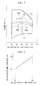
- the control unit stores a map or a relational expression, as shown in FIGS. 2 and 3 , in its storage area.
- the horizontal axis shows the centrifugal-chiller partial load factor
- the vertical axis shows the system COP, which represents the efficiency of the overall heat-source system.
- This map (optimum cooling-tower capacity relationship) shows the most efficient cooling-tower capacities of the cooling towers 5 in the overall heat-source system, in relation to the centrifugal-chiller partial load factor and the outside-air wet-bulb temperature.
- a curve L1 in the figure indicates the outside-air wet-bulb temperature serving as a threshold (first temperature).
- a cooling-tower capacity of 300% is the most efficient (the upper region in the figure).
- a cooling-tower capacity of 300% means a cooling-tower capacity that is three times (300%) the total rated capacity of the activated centrifugal-chillers 3.
- a line L2 in the figure indicates the centrifugal-chiller partial load factor serving as a threshold (the predetermined load factor).
- a cooling-tower capacity of 100% is the most efficient (the lower left region in the figure).
- a cooling-tower capacity of 200% is the maximum (the lower right region in the figure).
- isothermal lines La, Lb, Lc, and Ld of the outside-air wet-bulb temperature are shown for reference. The outside-air wet-bulb temperature increases in the sequence of La, Lb, L1, Lc, and Ld.
- FIG. 3 shows the relationship between the flow rate of the cooling-water pumps 15 and the centrifugal-chiller partial load factor.
- a cooling-water-pump flow rate of 100% is the rated flow rate.
- the control unit controls the cooling-water-pump flow rate based only on the centrifugal-chiller partial load factor, regardless of the outside-air wet-bulb temperature or the number of cooling towers 5 being operated.
- control becomes extremely simple.
- step S1 the load and the outside-air conditions are obtained. More specifically, the control unit obtains the chilled-water inlet temperature of the chilled water flowing into the evaporator 11 and the chilled-water outlet temperature flowing out of the evaporator 11 using temperature sensors. Then, the flow rate of the chilled water supplied by the chilled-water pumps 21 is obtained by a flowmeter. The control unit calculates the load consumed by the external load by multiplying the chilled-water inlet-outlet temperature difference obtained by the temperature sensors, the flow rate of the chilled water, the specific heat of the chilled water, and the specific weight of the chilled water. Furthermore, the control unit obtains the outside-air wet-bulb temperature from the moisture sensor provided on the cooling tower 5.
- step S2 the number of the centrifugal-chillers 3 being operated is determined such that the chilled-water inlet temperature is equal to or lower than a predetermined value, which is the conventional operation method (1); or such that the chilled-water inlet temperature can be maintained at or below a predetermined value and such that the COP of the centrifugal-chillers alone is the maximum, (2) (the "maximum COP operation" as used herein means an operation in which the number of the chillers to be operated is determined using the operation method disclosed in Japanese Unexamined Patent Application, Publication No. 2009-204262 ).
- the number of centrifugal-chillers 3 to be activated is determined for the centrifugal-chillers alone, independently of the number of the cooling towers 5 to be activated.
- step S3 the flow rate of the chilled-water pumps 21 is controlled.
- the flow rate of the chilled water in the chilled-water pumps 21 is determined according to the chilled water demand of the external load.
- step S4 by reducing the flow rate of the chilled-water pumps 21 to the maximum extent as long as the chilled water demand is met, the power consumption of the chilled-water pumps 21 is reduced as much as possible.
- the flow rate of the chilled water is reduced by reducing the rotational frequency of the electric motors that drive the chilled-water pumps 21, using inverter devices.
- the chilled water demand of the external load may be obtained either as the required amount of chilled water or as the pressure difference between the chilled-water outflow header 25 and the chilled-water inflow header 23, by which the necessary water can be delivered.
- step S5 the flow rate of the cooling-water pumps 15 is controlled.
- the flow rate of the cooling-water pumps 15 can be obtained in step S6 from a preliminarily obtained relational expression, as shown in FIG. 3 .
- This relational expression is described as a linear function with respect to the centrifugal-chiller partial load factor and is stored in the storage area of the control unit.
- control is performed such that the cooling-water flow rate is 100% at a centrifugal-chiller partial load factor of 100% (rated value) and such that the cooling-water flow rate is 50% at a centrifugal-chiller partial load factor of 20%, which is the minimum; that is, such that the cooling-water flow rate monotonically decreases as the centrifugal-chiller partial load factor decreases.
- the flow rate of the cooling-water pumps 15 is controlled separately and independently of the number of cooling towers.
- step S7 the number of the cooling towers 5 to be activated is determined.
- the required capacity for the cooling towers 5, QCTd is set to 300% (step S8).
- the required capacity QCTd means the cooling-tower capacity required when the cooling tower capacity corresponding to the rated capacity of one operating centrifugal-chiller 3 is 100%.
- a QCTd of 300% means requiring a cooling-tower capacity that is three times the rated capacity of one operating centrifugal-chiller 3 to the cooling towers.
- the required capacity for the cooling towers 5, QCTd is set 200% (step S8). In this case, the lower right region below the curve L1 and to the right of the line L2 in the map shown in FIG. 2 is required.
- the required capacity for the cooling towers 5, QCTd is set 100% (step S8). In this case, the lower left region below the curve L1 and to the left of the L2 in the map shown in FIG. 2 is required.
- step S9 the total required capacity ⁇ QCTd is calculated, which is the sum of the required capacities for the cooling towers 5 required by the respective operating centrifugal-chillers 3.
- the process proceeds to step S10, where the required capacity for the cooling towers required in step S8 is employed.
- step S11 the total required capacity ⁇ QCTd exceeds the total capacity of installed cooling towers ⁇ QCTi.
- the cooling-tower capacity QCTd' that can be required by each operating centrifugal-chiller 3 is the value obtained by dividing the total capacity of installed cooling towers ⁇ QCTi by the number of the operating centrifugal-chillers 3, N (step S12).
- the heat-source system COP which shows the efficiency of the overall heat-source system 1, is obtained by dividing the quantity of heat, which is obtained by subtracting the thermal input of the chilled-water pump from the quantity of heat output from the centrifugal-chiller, by the sum of the energy consumptions of the centrifugal-chillers, chilled-water pumps, cooling-water pumps, and cooling-tower fans, as shown in Expression 1.
- the thermal output of the heat-source system is subtraction of ⁇ mp ⁇ P chp from the thermal output of the centrifugal-chiller, Q tb . Note that the quantity of remaining heat of the chilled-water pump, (1- ⁇ mp ) ⁇ P chp , is released into the air.
- the energy consumption P tb is calculated by dividing the thermal output of the centrifugal-chiller, Q tb , by COP tb , which is obtained from the temperature of the cooling water, the centrifugal-chiller partial load factor, and the performance characteristics.
- the power consumption of the cooling-tower fan P ct [kW] is expressed as Expression 4.
- the power consumption of the rotational-speed-controlled cooling-tower fans is proportional to the cube of the airflow rate, and the airflow rate is proportional to the square of the rotational speed of the fans. Because typical open-type cooling towers have fans at the top of the towers, the amount of cooling water evaporated and released into the air is taken into consideration.
- Expression 4 to simplify the calculation, a method is employed in which the specific volume of the air is used as the intake conditions of the cooling towers and the amount of evaporated water is added.
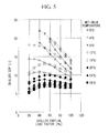
- FIG. 5 shows simulation results of the chiller COP, which shows the efficiency of the centrifugal-chillers alone, the simulation being performed under the above-described conditions.
- the horizontal axis represents the centrifugal-chiller partial load factor.
- the results are plotted for respective outside-air wet-bulb temperatures.
- the solid lines show the cooling-tower capacity of 100%, and the dashed lines show the cooling-tower capacity of 300%.
- the chiller COP increases at all the wet-bulb temperatures.
- the improvement in the chiller COP is small in a region where the load factor is low, i.e., about 20% to 40%.
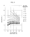
- FIG. 6 shows simulation results of the system COP, which shows the efficiency of the heat-source system 1, the simulation being performed under the same conditions as FIG. 5 .
- the solid lines show the cooling-tower capacity of 100%
- the dashed lines show the cooling-tower capacity of 300%.
- the centrifugal-chiller partial load factor with which the relationship between the system COP with a cooling-tower capacity of 300% and the system COP with a cooling-tower capacity of 100% is inverted moves to a higher load side as the outside-air wet-bulb temperature increases.
- the maximum COP occurs with a cooling-tower capacity of 300%, regardless of the centrifugal-chiller partial load factor. Furthermore, in a region where the outside-air wet-bulb temperature is higher than 8°C, a good COP occurs with a cooling-tower capacity of 200% in a region where the chiller load factor is higher than 60%, and the maximum COP occurs with a cooling-tower capacity of 100% in a region where the chiller load factor is equal to or lower than 60%.
- the energy saving effect can be obtained by increasing the cooling-tower capacity to 300%, regardless of the centrifugal-chiller partial load factor.
- the outside-air wet-bulb temperature is high and in a region where the centrifugal-chiller partial load factor is low, no advantage can be obtained from an increase in the cooling-tower capacity.
- the advantage due to an increase in the cooling-tower capacity may be obtained in a region where the chiller load factor is higher than a certain level, under conditions in which the wet-bulb temperature is high, such as in the summer period, it can be said that a moderate cooling-tower capacity of 200% is suitable.
- FIG. 8 shows simulation results of the chiller COP, which shows the efficiency of the centrifugal-chillers alone, when the specified rated cooling-water inlet-outlet temperature difference is 5°C and when the cooling-water flow rate is reduced from the rated value flow rate, 100%.
- the horizontal axis represents the centrifugal-chiller partial load factor. The results are plotted for respective outside-air wet-bulb temperatures.
- the solid lines show the cases where the cooling-water flow rate is not reduced (i.e., the cooling-water flow rate is 100%), and the dashed lines show the chiller COPs occurring at the cooling-water flow rates at which the chiller COP is maximized, for cases where the cooling-water flow rate is reduced from 100% in decrements of 5%.
- the chiller COP decreases at all the outside-air wet-bulb temperatures and all the centrifugal-chiller partial load factors. This is thought to be because the reduced cooling-water flow rate raises the temperature of the cooling water, increasing the power consumption of the centrifugal-chillers.
- FIG. 9 shows simulation results of the system COP, which shows the efficiency of the heat-source system 1, the simulation being performed under the same conditions as FIG. 8 .
- the solid lines show the cases where the cooling-water flow rate is not reduced
- the dashed lines show the system COPs occurring at the cooling-water flow rates at which the system COP is maximized, for cases where the cooling-water flow rate is reduced from 100% in decrements of 5%.
- the figure shows regions of the cooling-water flow rate, defined by dotted lines, where the maximum system COP occurs when the cooling-water flow rate is reduced. That is, in regions where the centrifugal-chiller partial load factor is high, the maximum system COP occurs at a cooling-water flow rate of 90%.
- the cooling-water flow rate at which the efficiency is maximized decreases, from 80% to 70% to 60% and to 50%.
- the system COP is improved at all the outside-air wet-bulb temperatures and all the centrifugal-chiller partial load factors. This means that the system COP increases despite a decrease in the chiller COP due to a reduction in the cooling-water flow rate (see FIG. 8 ), which is a new finding.
- the cooling-water flow rate at which the maximum system COP occurs decreases as the centrifugal-chiller partial load factor decreases. At the minimum centrifugal-chiller partial load factor, 20%, the cooling-water flow rate is the minimum, 50%.
- the influence of the outside-air wet-bulb temperature on the cooling-water flow rate relative to the centrifugal-chiller partial load factor is about 10%, which is not significant.
- the minimum cooling-water flow rate is 50%, independent of the outside-air wet-bulb temperature. Accordingly, it was found that expressing the cooling-water flow rate as a first order expression only in relation to the centrifugal-chiller partial load factor, as shown in FIG. 3 , is sufficient.
- a method for narrowing the 10% error range of the cooling-water flow rate may be employed, taking into consideration the outside-air wet-bulb temperature.
- FIG. 10 shows simulation results of the system COP, which shows the efficiency of the heat-source system, when the cooling-tower capacity is increased and the cooling-water flow rate is reduced.
- the horizontal axis represents the centrifugal-chiller partial load factor.
- the results are plotted for respective outside-air wet-bulb temperatures.
- the solid lines show points at which the maximum system COP occurs.
- the dotted lines define regions of the cooling-water flow rate where the maximum system COP occurs.
- regions of the cooling-tower capacity where the maximum system COP occurs are shown.
- the cooling-water flow rate at which the maximum system COP occurs decreases as the centrifugal-chiller partial load factor decreases.
- the cooling-water flow rate is the minimum, 50%. This is the same tendency as FIG. 9 , and it can be understood that the influence of an increase in the cooling-tower capacity on the optimum cooling-water flow rate is small. Accordingly, as shown in the flowchart in FIG. 4 , it is appropriate that the cooling-water flow rate is calculated (step S5), independently of an increase in the number of cooling towers (step S7).
- the combination of the outside-air wet-bulb temperature and the centrifugal-chiller partial load factor at which the maximum system COP occurs is obtained in advance as the map (optimum cooling-tower capacity relationship) shown in FIG. 2 , and, according to this map, the number of cooling towers to be activated is determined according to steps S7 to S12 shown in FIG. 4 .
- the cooling-water flow rate at which the maximum system COP occurs is obtained in advance as a relational expression shown in FIG. 3 , in relation to the centrifugal-chiller partial load factor. Then, according to this, the amount of the cooling water to be reduced is determined according to steps S5 to S6 shown in FIG. 4 .
- the heat-source system 1 and the method for controlling the same provide the following advantages. It was found that there is a cooling-tower capacity of the cooling towers 5 with which the heat-source system efficiency is maximized, depending on the outside-air wet-bulb temperature and the centrifugal-chiller partial load factor. Thus, a map showing the cooling-tower capacity with which the efficiency of the heat-source system is increased is obtained in advance, in relation to the outside-air wet-bulb temperature and the centrifugal-chiller partial load factor, and operation is performed according to the map. In this way, high-efficiency operation of the overall heat-source system can be realized. Furthermore, because the number of cooling towers 5 to be operated can be determined simply by obtaining the outside-air wet-bulb temperature and the centrifugal-chiller partial load factor, extremely simple operation control can be realized.
- the efficiency of the overall heat-source system is increased by determining the number of cooling towers 5 to be operated such that the cooling-tower capacity is 300% (first capacity), which is larger than the rated capacity of the operating centrifugal-chiller, when the outside-air wet-bulb temperature is equal to or lower than the first predetermined temperature (the outside-air wet-bulb temperature indicated by the curve L1 in FIG. 2 ).
- the efficiency of the overall heat-source system is increased by determining the number of cooling towers to be operated such that the cooling-tower capacity is 100%, which is equal to the rated capacity of the operating centrifugal-chiller 3, when the outside-air wet-bulb temperature is higher than the first predetermined temperature (the outside-air wet-bulb temperature indicated by the curve L1 in FIG. 2 ) and the centrifugal-chiller partial load factor is equal to or lower than 60% (the predetermined load factor). Accordingly, high-efficiency operation is realized by performing this operation during an intermediate period when the outside-air wet-bulb temperature is relatively high and the quantity of heat required by the external load is small.
- the efficiency of the overall heat-source system is increased by determining the number of cooling towers to be operated such that the cooling-tower capacity is 200%, when the outside-air wet-bulb temperature is equal to or higher than the first predetermined temperature (the outside-air wet-bulb temperature indicated by the curve L1 in FIG. 2 ) and the centrifugal-chiller partial load factor is equal to or higher than 60% (the predetermined load factor). Accordingly, high-efficiency operation is realized by performing this operation during the summer period when the outside-air wet-bulb temperature is relatively high and the quantity of heat required by the external load is large.
- the flow rate of the cooling-water pumps 15 is controlled based on the centrifugal-chiller partial load factor, not the outside-air wet-bulb temperature or the number of cooling towers 5 to be operated.
- simplified operation control is realized. Furthermore, by combining this control with the case where the number of cooling towers 5 to be operated is optimized from the standpoint of the efficiency, the heat-source system can be operated at an even higher efficiency.
Landscapes
- Engineering & Computer Science (AREA)
- Mechanical Engineering (AREA)
- General Engineering & Computer Science (AREA)
- Physics & Mathematics (AREA)
- Thermal Sciences (AREA)
- Air Conditioning Control Device (AREA)
Applications Claiming Priority (2)
| Application Number | Priority Date | Filing Date | Title |
|---|---|---|---|
| JP2009083371A JP5404132B2 (ja) | 2009-03-30 | 2009-03-30 | 熱源システムおよびその制御方法 |
| PCT/JP2010/055531 WO2010113850A1 (ja) | 2009-03-30 | 2010-03-29 | 熱源システムおよびその制御方法 |
Publications (2)
| Publication Number | Publication Date |
|---|---|
| EP2416082A1 true EP2416082A1 (de) | 2012-02-08 |
| EP2416082A4 EP2416082A4 (de) | 2018-03-14 |
Family
ID=42828140
Family Applications (1)
| Application Number | Title | Priority Date | Filing Date |
|---|---|---|---|
| EP10758621.6A Withdrawn EP2416082A4 (de) | 2009-03-30 | 2010-03-29 | Wärmequellensystem und steuerverfahren dafür |
Country Status (5)
| Country | Link |
|---|---|
| US (1) | US8646284B2 (de) |
| EP (1) | EP2416082A4 (de) |
| JP (1) | JP5404132B2 (de) |
| CN (1) | CN102341656B (de) |
| WO (1) | WO2010113850A1 (de) |
Cited By (1)
| Publication number | Priority date | Publication date | Assignee | Title |
|---|---|---|---|---|
| CN107062472A (zh) * | 2017-03-08 | 2017-08-18 | 大连国霖技术有限公司 | 自然冷却机组与离心冷水机组相结合的双冷源制冷系统 |
Families Citing this family (37)
| Publication number | Priority date | Publication date | Assignee | Title |
|---|---|---|---|---|
| US10845067B2 (en) | 2010-05-18 | 2020-11-24 | Energy & Enviornmental Research Center | Hygroscopic cooling tower for waste water disposal |
| US10808948B2 (en) | 2010-05-18 | 2020-10-20 | Energy & Environmental Research Center | Heat dissipation systems with hygroscopic working fluid |
| US10260761B2 (en) | 2010-05-18 | 2019-04-16 | Energy & Environmental Research Center Foundation | Heat dissipation systems with hygroscopic working fluid |
| JP5715455B2 (ja) * | 2011-03-15 | 2015-05-07 | 株式会社Nttファシリティーズ | 空調機とデータ処理負荷分配の連係制御方法 |
| JP5777929B2 (ja) * | 2011-04-22 | 2015-09-09 | 株式会社日立製作所 | 冷熱源装置の運転制御システム |
| JP5755013B2 (ja) * | 2011-04-25 | 2015-07-29 | 三菱重工業株式会社 | 熱源システムの冷却水流量制御方法 |
| JP5843630B2 (ja) * | 2012-01-25 | 2016-01-13 | 三菱電機株式会社 | 冷却システム |
| JP6090904B2 (ja) | 2012-02-29 | 2017-03-08 | 三菱重工業株式会社 | 冷却塔制御装置、冷却塔制御方法、及び熱源システム |
| JP6066648B2 (ja) * | 2012-09-27 | 2017-01-25 | 三菱重工業株式会社 | 熱源システム及びその制御方法 |
| US20140202177A1 (en) * | 2013-01-22 | 2014-07-24 | Charles Warrener Rush | Cooling water process control system |
| US10408712B2 (en) | 2013-03-15 | 2019-09-10 | Vertiv Corporation | System and method for energy analysis and predictive modeling of components of a cooling system |
| US10006685B2 (en) | 2014-06-03 | 2018-06-26 | Trane International Inc. | System and method for controlling a cooling system |
| WO2016009498A1 (ja) * | 2014-07-15 | 2016-01-21 | 株式会社インティ | 冷凍システム、コントローラ、及び冷却塔 |
| KR20160043402A (ko) * | 2014-10-13 | 2016-04-21 | 엘지전자 주식회사 | 칠러용 컨트롤러 및 칠러의 제어방법 |
| JP6408972B2 (ja) * | 2015-10-05 | 2018-10-17 | 日本エア・リキード株式会社 | 冷却塔制御システムおよび冷却塔制御方法 |
| CN107305082B (zh) * | 2016-04-21 | 2021-08-31 | 开利公司 | 冷却器系统、其中间水温获取方法及其控制方法 |
| CN106123215B (zh) * | 2016-06-27 | 2019-04-16 | 新奥泛能网络科技股份有限公司 | 一种空调冷却水系统控制方法及装置 |
| US11280511B2 (en) | 2016-09-02 | 2022-03-22 | Johnson Controls Technology Company | Systems and methods for evaporative heat rejection equipment fan speed control |
| CN108626923B (zh) * | 2017-03-15 | 2021-10-22 | 约克广州空调冷冻设备有限公司 | 一种空调系统的控制结构以及控制方法 |
| KR102364621B1 (ko) * | 2017-04-04 | 2022-02-17 | 엘지전자 주식회사 | 공기조화기 시스템 및 그 제어방법 |
| JP7149800B2 (ja) * | 2018-10-15 | 2022-10-07 | 東京瓦斯株式会社 | 冷却塔システム |
| JP7844768B2 (ja) * | 2019-04-26 | 2026-04-14 | ダイキン工業株式会社 | 熱源システム、目標運転容量推定方法、目標運転容量推定プログラム |
| JP6866447B2 (ja) * | 2019-10-01 | 2021-04-28 | 新菱冷熱工業株式会社 | 熱源システム制御方法及びその装置 |
| IT201900024138A1 (it) * | 2019-12-16 | 2021-06-16 | Daikin Applied Europe S P A | Metodo per effettuare una valutazione diagnostica di un refrigeratore |
| CN111720935B (zh) * | 2020-08-03 | 2025-06-24 | 付宝禄 | 一种智能冷源高效管路系统 |
| CN112129015A (zh) * | 2020-09-27 | 2020-12-25 | 厦门烟草工业有限责任公司 | 制冷系统及其控制方法 |
| CN112556222A (zh) * | 2020-12-14 | 2021-03-26 | 珠海格力电器股份有限公司 | 船用空调及基于船用空调的海水流量检测控制方法和装置 |
| KR102483126B1 (ko) * | 2021-04-14 | 2022-12-30 | 유병천 | 공조시스템의 에너지 절감을 위한 운전제어방법 및 이를 이용한 공조기 제어시스템 |
| CN114110946B (zh) * | 2021-11-12 | 2022-09-09 | 贵州绿云科技有限公司 | 水冷式中央空调自然冷却充分利用的控制方法及装置 |
| CN116772370A (zh) | 2022-03-09 | 2023-09-19 | 开利公司 | 混合热系统、其能力分配控制方法、可读存储介质及控制系统 |
| CN114623636B (zh) * | 2022-05-17 | 2023-02-03 | 中国空气动力研究与发展中心高速空气动力研究所 | 一种用于冷却水温度分类调节的循环水系统 |
| CN114791163B (zh) * | 2022-06-23 | 2022-09-06 | 蘑菇物联技术(深圳)有限公司 | 用于控制中央空调系统的方法、设备和介质 |
| CN115235051B (zh) * | 2022-07-27 | 2023-03-14 | 广州市铭汉科技股份有限公司 | 一种双控式冷却水控制系统 |
| CN116222097A (zh) * | 2022-12-29 | 2023-06-06 | 佛山中科融谷科技有限公司 | 一种低阻力变流场控制供冷装置及控制方法 |
| CN116007072B (zh) * | 2023-01-28 | 2025-10-28 | 青岛海信日立空调系统有限公司 | 一种中央空调系统及其控制方法 |
| CN117968326A (zh) * | 2024-01-19 | 2024-05-03 | 中国恩菲工程技术有限公司 | 制冷系统及其控制方法 |
| CN120740364B (zh) * | 2025-09-03 | 2025-12-30 | 深圳市前海能源科技发展有限公司 | 冷却塔集群系统、控制方法、设备及介质 |
Family Cites Families (30)
| Publication number | Priority date | Publication date | Assignee | Title |
|---|---|---|---|---|
| US4926649A (en) * | 1987-06-11 | 1990-05-22 | Martinez Jr George | Method and apparatus for saving energy in an air conditioning system |
| JP2742407B2 (ja) * | 1996-06-24 | 1998-04-22 | 日本たばこ産業株式会社 | 冷却水温度のマトリックス制御方法 |
| US6405543B2 (en) * | 1997-05-16 | 2002-06-18 | Work Smart Energy Enterprises Inc. | High-efficiency air-conditioning system with high-volume air distribution |
| US5946926A (en) * | 1998-04-07 | 1999-09-07 | Hartman; Thomas B. | Variable flow chilled fluid cooling system |
| US6185946B1 (en) * | 1999-05-07 | 2001-02-13 | Thomas B. Hartman | System for sequencing chillers in a loop cooling plant and other systems that employ all variable-speed units |
| US20030000230A1 (en) * | 1999-06-25 | 2003-01-02 | Kopko William L. | High-efficiency air handler |
| US6848267B2 (en) * | 2002-07-26 | 2005-02-01 | Tas, Ltd. | Packaged chilling systems for building air conditioning and process cooling |
| US6532754B2 (en) * | 2001-04-25 | 2003-03-18 | American Standard International Inc. | Method of optimizing and rating a variable speed chiller for operation at part load |
| US6718779B1 (en) * | 2001-12-11 | 2004-04-13 | William R. Henry | Method to optimize chiller plant operation |
| JP2003336891A (ja) | 2002-05-22 | 2003-11-28 | Daikin Ind Ltd | 冷凍装置の制御方法および冷凍装置 |
| JP3783859B2 (ja) | 2002-07-19 | 2006-06-07 | 日立プラント建設株式会社 | 空調設備及びその制御方法 |
| JP4435533B2 (ja) * | 2003-10-09 | 2010-03-17 | 高砂熱学工業株式会社 | 熱源システム及び制御装置 |
| JP2005214608A (ja) * | 2004-01-31 | 2005-08-11 | Kiyoshi Yanagimachi | 空気調和設備の省エネルギー改善の方法 |
| JP4167190B2 (ja) * | 2004-02-20 | 2008-10-15 | 三菱重工業株式会社 | 冷凍システムおよびその運転方法 |
| JP4422572B2 (ja) | 2004-07-29 | 2010-02-24 | 東洋熱工業株式会社 | 冷温熱源機の冷温水制御方法 |
| JP4435651B2 (ja) | 2004-08-31 | 2010-03-24 | 東洋熱工業株式会社 | 冷温水システムの冷温熱源機出力分配制御方法 |
| JP4630702B2 (ja) * | 2005-03-28 | 2011-02-09 | 三機工業株式会社 | 熱源システム最適運転制御装置 |
| JP4594146B2 (ja) | 2005-03-29 | 2010-12-08 | 東洋熱工業株式会社 | 空調システムの変風量最適制御方法 |
| US7698906B2 (en) * | 2005-12-30 | 2010-04-20 | Nexajoule, Inc. | Sub-wet bulb evaporative chiller with pre-cooling of incoming air flow |
| CN2909078Y (zh) | 2005-12-31 | 2007-06-06 | 东莞市广大制冷有限公司 | 可自动调节冷却水及冷冻水流量的中央空调系统 |
| HK1086984A2 (en) * | 2006-02-23 | 2006-09-29 | Man Chu Lau David | An industrial process efficiency method and system |
| JP2007240131A (ja) * | 2006-03-03 | 2007-09-20 | Es Systems Kk | 熱源機廻りの最適化制御 |
| JP4594276B2 (ja) | 2006-05-26 | 2010-12-08 | 東洋熱工業株式会社 | 冷温熱源機の冷温水制御方法及びこれに用いる空調システム |
| JP4505436B2 (ja) * | 2006-06-19 | 2010-07-21 | 東洋熱工業株式会社 | 冷却塔群の省エネルギー運転方法及びこれに用いる冷却塔群 |
| JP4994754B2 (ja) * | 2006-09-12 | 2012-08-08 | 株式会社九電工 | 熱源システム |
| JP2008070067A (ja) | 2006-09-15 | 2008-03-27 | Yamatake Corp | 冷凍機運転台数決定装置および方法 |
| JP2008134013A (ja) * | 2006-11-29 | 2008-06-12 | Toyo Netsu Kogyo Kk | 冷熱源機の運転制御方法及びこれを用いた冷熱源システム |
| TWI326018B (en) * | 2006-12-27 | 2010-06-11 | Ind Tech Res Inst | Method to optimize chiller system |
| JP4943880B2 (ja) | 2007-02-01 | 2012-05-30 | 東洋熱工業株式会社 | 冷却塔の冷却水給排水方法及びこれを用いた冷却塔群の冷却水給排水方法 |
| JP5244420B2 (ja) | 2008-02-28 | 2013-07-24 | 三菱重工業株式会社 | ターボ冷凍機および熱源システムならびにこれらの制御方法 |
-
2009
- 2009-03-30 JP JP2009083371A patent/JP5404132B2/ja active Active
-
2010
- 2010-03-29 US US13/146,811 patent/US8646284B2/en active Active
- 2010-03-29 EP EP10758621.6A patent/EP2416082A4/de not_active Withdrawn
- 2010-03-29 CN CN201080009831.5A patent/CN102341656B/zh active Active
- 2010-03-29 WO PCT/JP2010/055531 patent/WO2010113850A1/ja not_active Ceased
Non-Patent Citations (1)
| Title |
|---|
| See references of WO2010113850A1 * |
Cited By (1)
| Publication number | Priority date | Publication date | Assignee | Title |
|---|---|---|---|---|
| CN107062472A (zh) * | 2017-03-08 | 2017-08-18 | 大连国霖技术有限公司 | 自然冷却机组与离心冷水机组相结合的双冷源制冷系统 |
Also Published As
| Publication number | Publication date |
|---|---|
| JP5404132B2 (ja) | 2014-01-29 |
| CN102341656B (zh) | 2014-06-25 |
| US20110283718A1 (en) | 2011-11-24 |
| CN102341656A (zh) | 2012-02-01 |
| WO2010113850A1 (ja) | 2010-10-07 |
| US8646284B2 (en) | 2014-02-11 |
| EP2416082A4 (de) | 2018-03-14 |
| JP2010236728A (ja) | 2010-10-21 |
Similar Documents
| Publication | Publication Date | Title |
|---|---|---|
| US8646284B2 (en) | Heat-source system and method for controlling the same | |
| US4471630A (en) | Cooling system having combination of compression and absorption type units | |
| US6257007B1 (en) | Method of control of cooling system condenser fans and cooling tower fans and pumps | |
| CN106482376A (zh) | 制冷或热泵系统及其冷媒循环量调节方法 | |
| KR20130069805A (ko) | 열원 시스템 및 열원 시스템의 대수 제어 방법 | |
| JP5496182B2 (ja) | 冷凍機 | |
| CN102105752A (zh) | 空调装置 | |
| JP2010054152A (ja) | 熱源システムおよびその制御方法 | |
| US20090293724A1 (en) | Water extractor and a method of extracting water | |
| CN108397942A (zh) | 一种制冷系统的运行方法 | |
| JP5180616B2 (ja) | 冷房機等の省エネルギ装置 | |
| JP4167190B2 (ja) | 冷凍システムおよびその運転方法 | |
| JP5180130B2 (ja) | 水蒸気圧縮冷凍機システム | |
| CN103348196A (zh) | 热源系统及其控制方法 | |
| WO2013041897A1 (en) | Method for improving the efficiency of an air conditioning system for a cabin of a vehicle | |
| CN119737682A (zh) | 水源多联机控制方法、装置、水源多联机及存储介质 | |
| CN103906985A (zh) | 具有蒸发盘的制冷器具 | |
| JP5336268B2 (ja) | 冷却システム及び冷却方法 | |
| JP5971964B2 (ja) | ターボ冷凍機 | |
| RU2488750C2 (ru) | Холодильник с регулированием задаваемых установок | |
| CN112513542A (zh) | 用于基于预估流量来控制蒸气压缩系统的方法 | |
| JP2004020143A (ja) | 風力利用ヒートポンプ装置 | |
| JP3888814B2 (ja) | 製氷用冷却装置 | |
| EP1616136B1 (de) | Kühlsystem und verfahren zum betrieb eines solchen systems | |
| JP3854586B2 (ja) | 熱源システムと当該熱源システムの制御方法及び熱源と当該熱源の制御方法 |
Legal Events
| Date | Code | Title | Description |
|---|---|---|---|
| PUAI | Public reference made under article 153(3) epc to a published international application that has entered the european phase |
Free format text: ORIGINAL CODE: 0009012 |
|
| 17P | Request for examination filed |
Effective date: 20110720 |
|
| AK | Designated contracting states |
Kind code of ref document: A1 Designated state(s): AT BE BG CH CY CZ DE DK EE ES FI FR GB GR HR HU IE IS IT LI LT LU LV MC MK MT NL NO PL PT RO SE SI SK SM TR |
|
| DAX | Request for extension of the european patent (deleted) | ||
| RAP1 | Party data changed (applicant data changed or rights of an application transferred) |
Owner name: MITSUBISHI HEAVY INDUSTRIES THERMAL SYSTEMS, LTD. |
|
| RA4 | Supplementary search report drawn up and despatched (corrected) |
Effective date: 20180212 |
|
| RIC1 | Information provided on ipc code assigned before grant |
Ipc: F25B 1/053 20060101AFI20180206BHEP Ipc: F28F 27/00 20060101ALI20180206BHEP Ipc: F28B 9/06 20060101ALI20180206BHEP Ipc: F25B 49/02 20060101ALI20180206BHEP Ipc: F28C 1/00 20060101ALI20180206BHEP |
|
| 17Q | First examination report despatched |
Effective date: 20190214 |
|
| GRAP | Despatch of communication of intention to grant a patent |
Free format text: ORIGINAL CODE: EPIDOSNIGR1 |
|
| INTG | Intention to grant announced |
Effective date: 20191218 |
|
| STAA | Information on the status of an ep patent application or granted ep patent |
Free format text: STATUS: THE APPLICATION IS DEEMED TO BE WITHDRAWN |
|
| 18D | Application deemed to be withdrawn |
Effective date: 20200603 |