EP2416112B1 - Formmessvorrichtung - Google Patents
Formmessvorrichtung Download PDFInfo
- Publication number
- EP2416112B1 EP2416112B1 EP11176393A EP11176393A EP2416112B1 EP 2416112 B1 EP2416112 B1 EP 2416112B1 EP 11176393 A EP11176393 A EP 11176393A EP 11176393 A EP11176393 A EP 11176393A EP 2416112 B1 EP2416112 B1 EP 2416112B1
- Authority
- EP
- European Patent Office
- Prior art keywords
- signal
- unit
- output
- light intensity
- path length
- Prior art date
- Legal status (The legal status is an assumption and is not a legal conclusion. Google has not performed a legal analysis and makes no representation as to the accuracy of the status listed.)
- Active
Links
Images


Classifications
-
- G—PHYSICS
- G01—MEASURING; TESTING
- G01B—MEASURING LENGTH, THICKNESS OR SIMILAR LINEAR DIMENSIONS; MEASURING ANGLES; MEASURING AREAS; MEASURING IRREGULARITIES OF SURFACES OR CONTOURS
- G01B9/00—Measuring instruments characterised by the use of optical techniques
- G01B9/02—Interferometers
- G01B9/02083—Interferometers characterised by particular signal processing and presentation
-
- G—PHYSICS
- G01—MEASURING; TESTING
- G01B—MEASURING LENGTH, THICKNESS OR SIMILAR LINEAR DIMENSIONS; MEASURING ANGLES; MEASURING AREAS; MEASURING IRREGULARITIES OF SURFACES OR CONTOURS
- G01B11/00—Measuring arrangements characterised by the use of optical techniques
- G01B11/24—Measuring arrangements characterised by the use of optical techniques for measuring contours or curvatures
- G01B11/2441—Measuring arrangements characterised by the use of optical techniques for measuring contours or curvatures using interferometry
-
- G—PHYSICS
- G01—MEASURING; TESTING
- G01B—MEASURING LENGTH, THICKNESS OR SIMILAR LINEAR DIMENSIONS; MEASURING ANGLES; MEASURING AREAS; MEASURING IRREGULARITIES OF SURFACES OR CONTOURS
- G01B9/00—Measuring instruments characterised by the use of optical techniques
- G01B9/02—Interferometers
- G01B9/02055—Reduction or prevention of errors; Testing; Calibration
- G01B9/0207—Error reduction by correction of the measurement signal based on independently determined error sources, e.g. using a reference interferometer
-
- G—PHYSICS
- G01—MEASURING; TESTING
- G01B—MEASURING LENGTH, THICKNESS OR SIMILAR LINEAR DIMENSIONS; MEASURING ANGLES; MEASURING AREAS; MEASURING IRREGULARITIES OF SURFACES OR CONTOURS
- G01B9/00—Measuring instruments characterised by the use of optical techniques
- G01B9/02—Interferometers
- G01B9/0209—Low-coherence interferometers
Definitions
- the present invention relates to a shape measuring apparatus for measuring the position of a measuring face on the basis of the light applied from a light source having a wideband spectrum to the measuring face and the interference intensity of the light applied to a reference face.
- a white light interferometer is known as a shape measuring apparatus capable of three-dimensionally measuring very small objects to be measured, such as micromachines and LSIs.
- the white light applied from a white light source to an object to be measured and reflected by the object to be measured is made to interfere with the white light applied from the white light source to a reference face and reflected by the reference face, a reference face position having the largest interfering light intensity is detected while the reference face is moved in the direction of the optical axis, and the height of the object to be measured in the direction of the optical axis is measured on the basis of this reference face position (refer to International publication No. 2006-068217).
- a shape measuring apparatus is known as an apparatus of using simplified arithmetic processing in which the weighted average of inspection positions is calculated while the absolute value of the difference value between the interference fringe intensity values obtained before and after an optical path length difference is changed by a predetermined amount is used as a weight, and the value indicated by the weighted average is obtained as a peak position at which the absolute value of the difference value becomes the largest (refer to Japanese Patent No. 3220955 ).
- an object of the present invention is to provide a shape measuring apparatus capable of obtaining stable and accurate measurement results while suppressing the influence of noise.
- a shape measuring apparatus including: a light source having a wideband spectrum; an optical system configured to guide the light from the light source to an object to be measured and a reference face, configured to combine the light reflected from the object to be measured and the light reflected from the reference face, and configured to generate an interfering light intensity distribution image indicating interfering light intensity that corresponds to each measurement position inside the measuring face of the object to be measured and changes depending on the difference between a first optical path length from the light source to the object to be measured and a second optical path length from the light source to the reference face; an imaging unit configured to image the interfering light intensity distribution image output from the optical system; an optical path length difference changing unit configured to change the optical path length difference between the first optical path length and the second optical path length; an image storing unit configured to sequentially store interfering light intensity distribution images that are imaged using the imaging unit and changed depending on the change in the optical path length difference; and an arithmetic processing unit configured to obtain the peak value of an inter
- a signal subtracting unit configured to subtract the output of the second signal adding unit from the interfering light intensity sequence, and configured to output the result of the subtraction as an error signal
- an adaptive signal processing block having an adaptive algorithm section for adjusting the weights of the weighting unit on the basis of the error signal so that the error signal becomes smallest
- a peak detection block configured to detect the peak position of the detection signal.
- the adaptive algorithm section may execute algorithm using an RLS (Recursive Least Square) method.
- RLS Recursive Least Square
- the peak detection block may include: a squaring unit configured to output the squared value of the detection signal; an integrating unit configured to integrate the output signal from the squaring unit, and configured to output the obtained signal; a smoothing and differentiating unit configured to smooth and differentiate the output signal from the integrating unit, and configured to output the obtained signal; and a peak position detecting unit configured to detect the peak value from the output signal of the smoothing and differentiating unit.
- FIG. 1 is a view showing a configuration of a white light interferometer serving as the shape measuring apparatus according to this embodiment.
- a Michelson interferometer is shown herein, another equivalent interferometer, such as a Mirau interferometer, can also be used.
- an interferometer being used in combination with another optical measuring apparatus, such as an image measuring apparatus, may be used.
- a light source 1 is a white light source having a wideband spectrum, such as a halogen lamp, a Xenon lamp, a mercury lamp, a metal halide lamp or an LED.
- the white light emitted from the light source 1 is collimated by a collimator lens 2 and split by a beam splitter 3 into two directions.
- One of the split beams is applied to the measuring face of a workpiece 4 serving as an object to be measured, and the other split beam is applied to the reference face of a reference plate 5.
- the white light beams respectively reflected by the measuring face and the reference face are combined by the beam splitter 3.
- the interfering light obtained at that time is imaged by a CCD camera 8 via an imaging lens 7.
- the reference plate 5 is moved and scanned in the direction of the optical axis using a drive unit 6, such as a piezo element.
- An interference image at each scanning position is sampled using the CCD camera 8 and stored in an image memory 9.
- An arithmetic processing section 10 determines the position of the measuring face of the workpiece 4 in the height direction thereof on the basis of the intensity of the interfering light at each measurement position on the measuring face of the workpiece 4 and the scanning position information of the reference plate 5 being input from an encoder 14. Furthermore, the arithmetic processing section 10 is equipped with an adaptive signal processing block 100 ( FIG. 4 ) for eliminating noise and a peak detection block 110 ( FIG.
- the white light from the light source 1 is reflected by the measuring face of the workpiece 4 and the reference face of the reference plate 5 and combined by the beam splitter 3.
- the intensity of the interfering light at that time is determined by the optical path length difference between a first optical path length from the light source 1 to the workpiece 4 and a second optical path length from the light source 1 to the reference plate 5.
- the intensity of the interfering light becomes largest.
- the intensity of the interfering light is changed by moving and scanning the reference plate 5 in the direction of the optical axis using the piezo element 6.
- the range in which interference fringes are generated can be narrowed using white light having low coherence. Hence, as shown in FIG.
- the change in the intensity of the interfering light at each position on the measuring face, generated by the movement and scanning of the reference face, is generated at a phase corresponding to the height of the measuring face (the position in the Z direction). For this reason, the scanning position of the reference face at which the peak value of the change in the intensity of the interfering light at each position on the measuring face is observed can be obtained as the height of a portion corresponding to the measuring face.
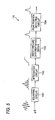
- FIG. 3 is a flowchart showing the shape measuring method.
- the reference plate 5 is moved in the direction of the optical axis by a predetermined amount (at S1), and the two-dimensional distribution image of the intensity of the interfering light on the measuring face is stored in the image memory 9 (at S2). These two steps are repeated by the number of times corresponding to a predetermined sampling number (at S3).
- the peak position of interfering light intensity sequence indicating the change in the intensity of the interfering light due to the change in the optical path length difference at each measurement position on the measuring face is detected as shown in FIG. 2 (at S4). Then, the detected peak position at each measurement position is displayed and output as the height at the measurement position (at S5).
- the interfering light intensity sequence indicating the change in the intensity of the interfering light includes noise due to the influence of the material of the workpiece 4, measurement environment, etc., whereby the S/N ratio thereof is decreased or the baseline thereof fluctuates as shown in FIG. 6A .
- the adaptive signal processing block 100 included in the arithmetic processing section 10 eliminates this noise. As a result, the fluctuation of the baseline and the noise content are eliminated as shown in FIG. 6B .
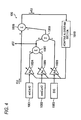
- FIG. 4 is a block diagram showing a configuration of the adaptive signal processing block 100.
- the adaptive signal processing block 100 has signal generating circuits 1001, 1002 and 1003 for generating a sine signal sin( ⁇ t) and a cosine signal cos( ⁇ t), oscillating at the center frequency ⁇ of the interfering light intensity sequence, and a direct-current signal DC, respectively. These signals are respectively weighted by weighting circuits 1004, 1005 and 1006.
- the outputs of the center frequency component weighting circuits 1004 and 1005 are added by an adder 1007 and then output as a detection signal g(t).
- the output of this adder 1007 and the output of the direct-current component weighting circuit 1006 are added by an adder 1008.
- a subtracter 1009 subtracts the output of the adder 1008 from the observation signal f(t) of the interfering light intensity sequence and then outputs an error signal e(t) as the result of the subtraction.
- This error signal e(t) is input to an adaptive algorithm section 1010.
- This adaptive algorithm section 1010 adaptively changes the weighting coefficients As, Ac and Ad of the weighting circuits 1004, 1005 and 1006 so that the error signal e(t) becomes smallest.
- the adaptive algorithm section 1010 can use an adaptive algorithm, such as an LMS (Least Mean Square) method or an RLS (Recursive Least Square) method, it is desired that the latter method, the RLS method, should be used because of its high convergence speed.
- the detection signal g(t) from which noise is eliminated as shown in FIG. 6B can be obtained from the observation signal f(t) of the interfering light intensity sequence including the noise shown in FIG. 6A .
- the observation signal f(t) in the adaptive signal processing block 100 can be represented by Expression 1, and the detection signal g(t) including only the component of the center frequency ⁇ and represented by Expression 2 is obtained by obtaining the weighting coefficients As, Ac and Ad so that the error signal e(t) becomes smallest.
- time-series sequential processing can be carried out each time the sample of the interfering light intensity sequence of each pixel is obtained.
- time-series sequential processing it is possible to carry out real-time processing in which sequential arithmetic processing and screen display are carried out simultaneously with the acquisition of each sample of the interfering light intensity sequence, and a displayed image is gradually renewed as the measurement proceeds.
- FIG. 5 is a block diagram showing a configuration of the peak detection block 110 in the apparatus.
- the peak detection block 110 has a squaring circuit 1101, an integrating circuit 1102, a smoothing and differentiating circuit 1103, and a peak position detecting circuit 1104, these being connected in this order.
- the detection signal g(t) is input to the peak detection block 110
- the detection signal g(t) is first squared by the squaring circuit 1101 and is integrated by the integrating circuit 1102.
- the obtained signal is smoothed and differentiated by the smoothing and differentiating circuit 1103.
- the peak position is detected by the peak position detecting circuit 1104.
- the obtained signal is not simply differentiated but is smoothed and differentiated, whereby it is possible to obtain the peak position stably.
- FIGS. 6A and 6B and FIGS. 7A and 7B show the input signal f(t) and the detection signal g(t) of the adaptive signal processing block 100.
- FIG. 6A shows an example in which the baseline of the input signal f(t) has fluctuated significantly during signal measurement.
- FIG. 6B shows the detection signal g(t) obtained when the input signal f(t) shown in FIG. 6A was input to the adaptive signal processing block 100. As shown in FIG. 6B , the fluctuation of the baseline is eliminated almost completely, and the S/N ratio is improved remarkably.
- FIG. 7A shows an example in which the detection signal component of the input signal f(t) is very weak in comparison with the fluctuation of the baseline.
- the baseline of the input signal f(t) fluctuates significantly and the signal component is swallowed up.
- FIG. 7B shows the detection signal g(t) obtained when the input signal f(t) shown in FIG. 7A was input to the adaptive signal processing block 100.
- the fluctuation of the baseline is eliminated almost completely, and the S/N ratio is improved remarkably,
- the detection signal g(t) in which the fluctuation of the baseline is suppressed can be output, and a stable and accurate measurement result can be obtained.
- FIGS. 8A and 8B show results obtained when a peak is detected at each pixel position and converted into shape data.
- FIG. 8A shows image data obtained according to the conventional shape measuring apparatus and
- FIG. 8B shows image data obtained according to this embodiment.
- the number of pixels is 307200 for both FIGS. 8A and 8B .
- the perforated portions in the figures indicate missing data.
- the number of the missing data in this embodiment has been decreased significantly in comparison with that in the conventional shape measuring apparatus.
- the number of the missing data in the conventional shape measuring apparatus is 6385 of the total number of pixels, 307200
- the number of the missing data in the shape measuring apparatus according to this embodiment is 2 of the total number of pixels, 307200.
- the stability of the shape measurement according to this embodiment has been improved significantly in comparison with that of the conventional shape measurement.
- the respective pixels can be processed individually.
- the speed of the arithmetic processing is improved abruptly.
- the processing for respective pixels can be parallelized completely.
- real-time parallel processing can be attained easily by combining the above-mentioned real-time processing.
- the detection signal is represented by Expression 2 in the first embodiment
- the detection signal is represented by Expression 3 in a third embodiment.
- A designates a signal amplitude
- ⁇ designates a signal phase, these being represented by Expression 4 and Expression 5, respectively.
- Expression 2 and Expression 3 represent the same thing.
- a and ⁇ are adjusted instead of As and Ac in the adaptive signal processing.
- a concept referred to as a forgetting constant is present in the RLS method. This represents that data up to which time point in the past should be utilized for estimation. Even for this forgetting constant, adequate values can be set to the respective A and ⁇ .
- the number of the components of the center frequency ⁇ is one is provided in the first embodiment, it may be possible that a plurality of components are used for the center frequency ⁇ so as to correspond to the wavelength components of the light source 1 to be used.
- a distribution in frequency instead of the single frequency ⁇ as in Expression 2 and Expression 3.
- more accurate estimation can be carried out by using an expression, such as Expression 6 described below.
- Expression 6 In consideration of real time performance, realistically, it is desired that calculation for approximately three components should be carried out using Expression 6.
- the maximum amplitude position can be estimated, and at the same time, the phase of each frequency component can be measured.
- the interfering light intensity sequence includes a plurality of frequencies as detailed above, the phases of the respective frequency components become coincident at the maximum amplitude position. Consequently, with the estimation method that uses Expression 6, it is possible to carry out estimation having higher accuracy by using not only amplitude but also phase information.
- g t ⁇ k A k ⁇ sin ⁇ k ⁇ t + ⁇ k
Landscapes
- Physics & Mathematics (AREA)
- General Physics & Mathematics (AREA)
- Engineering & Computer Science (AREA)
- Signal Processing (AREA)
- Length Measuring Devices By Optical Means (AREA)
Claims (3)
- Formmessvorrichtung, die umfasst:eine Lichtquelle (1), die ein Breitbandspektrum hat;ein optisches System (2, 3, 7), das so konfiguriert ist, dass es das Licht von der Lichtquelle zu einem zu messenden Objekt (4) und einer Bezugsfläche (5) leitet, so konfiguriert ist, dass es das von dem zu messenden Objekt reflektierte Licht und das von der Bezugsfläche reflektierte Licht kombiniert, und so konfiguriert ist, dass es ein Bild der Interferenzlicht-Intensitätsverteilung erzeugt, das Interferenzlicht-Intensität anzeigt, die jeder Messposition im Inneren der Messfläche des zu messenden Objektes entspricht und sich in Abhängigkeit von der Differenz zwischen einer ersten Lichtweg-Länge von der Lichtquelle zu dem zu messenden Objekt und einer zweiten Lichtweg-Länge von der Lichtquelle zu der Bezugsfläche ändert;eine Abbildungseinheit (8), die so konfiguriert ist, dass sie das von dem optischen System ausgegebene Bild der Interferenzlicht-Intensitätsverteilung abbildet;eine Einheit zum Ändern der Lichtweg-Längendifferenz, die so konfiguriert ist, dass sie die Lichtweg-Längendifferenz zwischen der ersten Lichtweg-Länge und der zweiten Lichtweg-Länge ändert;eine Bildspeichereinheit, die so konfiguriert ist, dass sie sequenziell Bilder der Interferenzlicht-Intensitätsverteilung speichert, die unter Verwendung der Bilderzeugungseinheit abgebildet und in Abhängigkeit von der Änderung der Lichtweg-Längendifferenz geändert werden; undeine Arithmetik-Verarbeitungseinheit (10), die so konfiguriert ist, dass sie den Spitzenwert einer Interferenzlicht-Intensitätssequenz ermittelt, die die Änderung der Interferenzlicht-Intensität aufgrund der Änderung der Lichtweg-Längendifferenz an jeder Messposition der in der Bildspeichereinheit gespeicherten Bilder der Interferenzlicht-Intensitätsverteilung anzeigt, und so konfiguriert ist, dass sie die Position des Spitzenwertes in der Richtung der optischen Achse an jeder Messposition des zu messenden Objektes ermittelt, wobei die Arithmetik-Verarbeitungseinheit enthält:eine Vielzahl von Signal-Erzeugungseinheiten (1001, 1002, 1003), die so konfiguriert sind, dass sie ein Gleichstromsignal und eine Vielzahl periodischer Signale erzeugen, wobei die Frequenzen der Vielzahl periodischer Signale von der Mittenfrequenz der Interferenzlicht-Intensitätssequenz abhängen;eine Gewichtungseinheit (1004, 1005, 1006), die so konfiguriert ist, dass sie die jeweiligen von der Vielzahl von Signal-Erzeugungseinheiten ausgegebenen Signale gewichtet;eine erste Signal-Addiereinheit (107), die so konfiguriert ist, dass sie die Vielzahl von der Gewichtungseinheit ausgegebenen gewichteten periodischen Signale zueinander addiert, und so konfiguriert ist, dass sie das ermittelte Signal als ein Erfassungssignal ausgibt;eine zweite Signal-Addiereinheit (1008), die so konfiguriert ist, dass sie das von der Gewichtungseinheit ausgegebene gewichtete Gleichstromsignal zu dem Erfassungssignal addiert;eine Signal-Subtrahiereinheit (1009), die so konfiguriert ist, dass sie den Ausgang der zweiten Signal-Addiereinheit von der Interferenzlicht-Intensitätssequenz subtrahiert, und so konfiguriert ist, dass sie das Ergebnis der Subtraktion als ein Fehlersignal ausgibt;einen Block (100) für adaptive Signalverarbeitung, der einen Abschnitt (1010) mit adaptivem Algorithmus aufweist, mit dem die Gewichte der Gewichtungseinheit auf Basis des Fehlersignals angepasst werden, so dass das Fehlersignal den kleinsten Wert annimmt; undeinen Spitzenwert-Erfassungsblock (110), der so konfiguriert ist, dass er die Spitzenwert-Position des Erfassungssignals erfasst.
- Formmessvorrichtung nach Anspruch 1, wobei
der Abschnitt (1010) mit adaptivem Algorithmus den Algorithmus unter Verwendung eines RLS-Verfahrens (Recursive Least Square method) ausführt. - Formmessvorrichtung nach Anspruch 1 oder Anspruch 2, wobei der Spitzenwert-Erfassungsblock (110) enthält:eine Quadriereinheit, die so konfiguriert ist, dass sie den quadrierten Wert des Erfassungssignals ausgibt;eine Integriereinheit, die so konfiguriert ist, dass sie das Ausgangssignal von der Quadriereinheit integriert, und so konfiguriert ist, dass sie das ermittelte Signal ausgibt; undeine Glätt-und-Differenzier-Einheit, die so konfiguriert ist, dass sie das Ausgangssignal von der Integriereinheit glättet und differenziert, und so konfiguriert ist, dass sie das ermittelte Signal ausgibt; undeine Spitzenpositions-Erfassungseinheit, die so konfiguriert ist, dass sie den Spitzenwert aus dem Ausgangssignal der Glätt-und-Differenzier-Einheit erfasst.
Applications Claiming Priority (1)
| Application Number | Priority Date | Filing Date | Title |
|---|---|---|---|
| JP2010177671A JP5493152B2 (ja) | 2010-08-06 | 2010-08-06 | 形状測定装置 |
Publications (2)
| Publication Number | Publication Date |
|---|---|
| EP2416112A1 EP2416112A1 (de) | 2012-02-08 |
| EP2416112B1 true EP2416112B1 (de) | 2013-03-27 |
Family
ID=44674196
Family Applications (1)
| Application Number | Title | Priority Date | Filing Date |
|---|---|---|---|
| EP11176393A Active EP2416112B1 (de) | 2010-08-06 | 2011-08-03 | Formmessvorrichtung |
Country Status (3)
| Country | Link |
|---|---|
| US (1) | US8520216B2 (de) |
| EP (1) | EP2416112B1 (de) |
| JP (1) | JP5493152B2 (de) |
Families Citing this family (5)
| Publication number | Priority date | Publication date | Assignee | Title |
|---|---|---|---|---|
| JP2014109481A (ja) * | 2012-11-30 | 2014-06-12 | Canon Inc | 計測方法及び計測装置 |
| JP2016070918A (ja) * | 2014-10-01 | 2016-05-09 | 本田技研工業株式会社 | 成形物の製造方法、形状測定方法及び形状測定装置 |
| WO2016124399A1 (en) * | 2015-02-06 | 2016-08-11 | Asml Netherlands B.V. | A method and apparatus for improving measurement accuracy |
| JP6696624B2 (ja) * | 2017-05-24 | 2020-05-20 | 三菱電機ビルテクノサービス株式会社 | 形状測定装置 |
| JP7577342B2 (ja) * | 2022-03-31 | 2024-11-05 | santec Holdings株式会社 | 半導体ウエハの厚さ計測装置 |
Citations (1)
| Publication number | Priority date | Publication date | Assignee | Title |
|---|---|---|---|---|
| US20050225769A1 (en) * | 2002-03-14 | 2005-10-13 | Bankhead Andrew D | Surface profiling apparatus |
Family Cites Families (9)
| Publication number | Priority date | Publication date | Assignee | Title |
|---|---|---|---|---|
| US5402234A (en) | 1992-08-31 | 1995-03-28 | Zygo Corporation | Method and apparatus for the rapid acquisition of data in coherence scanning interferometry |
| JP3220955B2 (ja) | 1996-05-31 | 2001-10-22 | 株式会社東京精密 | 非接触表面形状測定方法及び装置 |
| JP4246326B2 (ja) * | 1999-08-27 | 2009-04-02 | 東レエンジニアリング株式会社 | 表面形状測定方法及びその装置 |
| AU2002241784A1 (en) * | 2000-11-02 | 2002-05-27 | Zygo Corporation | Height scanning interferometry method and apparatus including phase gap analysis |
| US7068376B2 (en) * | 2002-04-19 | 2006-06-27 | Zygo Corporation | Interferometry method and apparatus for producing lateral metrology images |
| JP4531495B2 (ja) | 2004-09-01 | 2010-08-25 | 株式会社アトラス | クレーンゲーム機 |
| TWI278598B (en) | 2004-12-22 | 2007-04-11 | Univ Electro Communications | 3D shape measurement device |
| JP2009002889A (ja) * | 2007-06-25 | 2009-01-08 | Mitsutoyo Corp | 誤差補正方法、誤差補正装置、及び誤差補正プログラム |
| US7649634B2 (en) | 2007-10-30 | 2010-01-19 | Mountain View Optical Consultant Corp. | Methods and systems for white light interferometry and characterization of films |
-
2010
- 2010-08-06 JP JP2010177671A patent/JP5493152B2/ja active Active
-
2011
- 2011-07-28 US US13/192,595 patent/US8520216B2/en active Active
- 2011-08-03 EP EP11176393A patent/EP2416112B1/de active Active
Patent Citations (1)
| Publication number | Priority date | Publication date | Assignee | Title |
|---|---|---|---|---|
| US20050225769A1 (en) * | 2002-03-14 | 2005-10-13 | Bankhead Andrew D | Surface profiling apparatus |
Also Published As
| Publication number | Publication date |
|---|---|
| JP2012037378A (ja) | 2012-02-23 |
| EP2416112A1 (de) | 2012-02-08 |
| JP5493152B2 (ja) | 2014-05-14 |
| US20120033229A1 (en) | 2012-02-09 |
| US8520216B2 (en) | 2013-08-27 |
Similar Documents
| Publication | Publication Date | Title |
|---|---|---|
| US7852489B2 (en) | Method for measuring surface profile, and apparatus using the same | |
| JP3065374B2 (ja) | 被検体の光学的検査方法、被検体の光学的検査装置、および被検体の光学的検査用干渉計 | |
| EP2416112B1 (de) | Formmessvorrichtung | |
| EP3594617A1 (de) | Vorrichtung zur messung dreidimensionaler formen, verfahren zur messung dreidimensionaler formen und programm | |
| JP5663758B2 (ja) | 形状測定方法及び形状測定装置 | |
| JP2019537726A (ja) | 干渉計の光学性能を最適化するための方法及び装置 | |
| CN106091974B (zh) | 一种物体形变测量仪器、方法和设备 | |
| Chen et al. | Real-time scanner error correction in white light interferometry | |
| JP6047764B2 (ja) | 白色干渉計、画像処理方法及び画像処理プログラム | |
| CN108692676A (zh) | 使用了扫描型白色干涉显微镜的三维形状计测方法 | |
| EP3012577B1 (de) | Verfahren zur vermessung einer verformung einer oberfläche eines objekts, computerprogramm und computerlesbares speichermedium | |
| Kucharski et al. | Radial image processing for phase extraction in rough-surface interferometry | |
| Dai et al. | Non-destructive strain determination based on phase measurement and radial basis function | |
| JP2010185844A (ja) | 表面形状測定方法およびこれを用いた装置 | |
| JP5454769B2 (ja) | 分光立体形状測定装置及び分光立体形状測定方法 | |
| WO2001090689A1 (fr) | Procede et appareil pour mesurer les interferences | |
| JP4218919B2 (ja) | 干渉縞解析方法 | |
| JP4390957B2 (ja) | 縞解析における縞位相決定方法 | |
| JPH11173808A (ja) | フリンジスキャン干渉計測の解析式の決定方法及びフリンジスキャン干渉計 | |
| JP7222524B2 (ja) | 物体内部の光学特性を計測する計測装置及び方法 | |
| Dowling | Three Dimensional Digital Image Correlation for Dynamic Measurements | |
| Su et al. | A real-time, full-field, and low-cost velocity sensing approach for linear motion using fringe projection techniques | |
| JP2001133215A (ja) | 干渉計測方法および干渉計測装置 | |
| JP2001201326A (ja) | 干渉縞測定解析方法 | |
| JP2023058332A (ja) | 検査システム、画像処理方法、および、欠陥検査装置 |
Legal Events
| Date | Code | Title | Description |
|---|---|---|---|
| AK | Designated contracting states |
Kind code of ref document: A1 Designated state(s): AL AT BE BG CH CY CZ DE DK EE ES FI FR GB GR HR HU IE IS IT LI LT LU LV MC MK MT NL NO PL PT RO RS SE SI SK SM TR |
|
| AX | Request for extension of the european patent |
Extension state: BA ME |
|
| PUAI | Public reference made under article 153(3) epc to a published international application that has entered the european phase |
Free format text: ORIGINAL CODE: 0009012 |
|
| 17P | Request for examination filed |
Effective date: 20120807 |
|
| GRAP | Despatch of communication of intention to grant a patent |
Free format text: ORIGINAL CODE: EPIDOSNIGR1 |
|
| RAP1 | Party data changed (applicant data changed or rights of an application transferred) |
Owner name: MITUTOYO CORPORATION |
|
| RIN1 | Information on inventor provided before grant (corrected) |
Inventor name: GOTO, TOMONORI Inventor name: MIYAKURA, JYOTA |
|
| GRAS | Grant fee paid |
Free format text: ORIGINAL CODE: EPIDOSNIGR3 |
|
| GRAA | (expected) grant |
Free format text: ORIGINAL CODE: 0009210 |
|
| AK | Designated contracting states |
Kind code of ref document: B1 Designated state(s): AL AT BE BG CH CY CZ DE DK EE ES FI FR GB GR HR HU IE IS IT LI LT LU LV MC MK MT NL NO PL PT RO RS SE SI SK SM TR |
|
| REG | Reference to a national code |
Ref country code: GB Ref legal event code: FG4D |
|
| REG | Reference to a national code |
Ref country code: CH Ref legal event code: EP |
|
| REG | Reference to a national code |
Ref country code: AT Ref legal event code: REF Ref document number: 603664 Country of ref document: AT Kind code of ref document: T Effective date: 20130415 |
|
| REG | Reference to a national code |
Ref country code: IE Ref legal event code: FG4D |
|
| REG | Reference to a national code |
Ref country code: DE Ref legal event code: R096 Ref document number: 602011001161 Country of ref document: DE Effective date: 20130523 |
|
| PG25 | Lapsed in a contracting state [announced via postgrant information from national office to epo] |
Ref country code: SE Free format text: LAPSE BECAUSE OF FAILURE TO SUBMIT A TRANSLATION OF THE DESCRIPTION OR TO PAY THE FEE WITHIN THE PRESCRIBED TIME-LIMIT Effective date: 20130327 Ref country code: BG Free format text: LAPSE BECAUSE OF FAILURE TO SUBMIT A TRANSLATION OF THE DESCRIPTION OR TO PAY THE FEE WITHIN THE PRESCRIBED TIME-LIMIT Effective date: 20130627 Ref country code: LT Free format text: LAPSE BECAUSE OF FAILURE TO SUBMIT A TRANSLATION OF THE DESCRIPTION OR TO PAY THE FEE WITHIN THE PRESCRIBED TIME-LIMIT Effective date: 20130327 Ref country code: NO Free format text: LAPSE BECAUSE OF FAILURE TO SUBMIT A TRANSLATION OF THE DESCRIPTION OR TO PAY THE FEE WITHIN THE PRESCRIBED TIME-LIMIT Effective date: 20130627 |
|
| REG | Reference to a national code |
Ref country code: AT Ref legal event code: MK05 Ref document number: 603664 Country of ref document: AT Kind code of ref document: T Effective date: 20130327 |
|
| REG | Reference to a national code |
Ref country code: LT Ref legal event code: MG4D |
|
| PG25 | Lapsed in a contracting state [announced via postgrant information from national office to epo] |
Ref country code: FI Free format text: LAPSE BECAUSE OF FAILURE TO SUBMIT A TRANSLATION OF THE DESCRIPTION OR TO PAY THE FEE WITHIN THE PRESCRIBED TIME-LIMIT Effective date: 20130327 Ref country code: LV Free format text: LAPSE BECAUSE OF FAILURE TO SUBMIT A TRANSLATION OF THE DESCRIPTION OR TO PAY THE FEE WITHIN THE PRESCRIBED TIME-LIMIT Effective date: 20130327 Ref country code: SI Free format text: LAPSE BECAUSE OF FAILURE TO SUBMIT A TRANSLATION OF THE DESCRIPTION OR TO PAY THE FEE WITHIN THE PRESCRIBED TIME-LIMIT Effective date: 20130327 Ref country code: GR Free format text: LAPSE BECAUSE OF FAILURE TO SUBMIT A TRANSLATION OF THE DESCRIPTION OR TO PAY THE FEE WITHIN THE PRESCRIBED TIME-LIMIT Effective date: 20130628 |
|
| REG | Reference to a national code |
Ref country code: NL Ref legal event code: VDEP Effective date: 20130327 |
|
| PG25 | Lapsed in a contracting state [announced via postgrant information from national office to epo] |
Ref country code: BE Free format text: LAPSE BECAUSE OF FAILURE TO SUBMIT A TRANSLATION OF THE DESCRIPTION OR TO PAY THE FEE WITHIN THE PRESCRIBED TIME-LIMIT Effective date: 20130327 Ref country code: HR Free format text: LAPSE BECAUSE OF FAILURE TO SUBMIT A TRANSLATION OF THE DESCRIPTION OR TO PAY THE FEE WITHIN THE PRESCRIBED TIME-LIMIT Effective date: 20130327 |
|
| PG25 | Lapsed in a contracting state [announced via postgrant information from national office to epo] |
Ref country code: RO Free format text: LAPSE BECAUSE OF FAILURE TO SUBMIT A TRANSLATION OF THE DESCRIPTION OR TO PAY THE FEE WITHIN THE PRESCRIBED TIME-LIMIT Effective date: 20130327 Ref country code: CZ Free format text: LAPSE BECAUSE OF FAILURE TO SUBMIT A TRANSLATION OF THE DESCRIPTION OR TO PAY THE FEE WITHIN THE PRESCRIBED TIME-LIMIT Effective date: 20130327 Ref country code: AT Free format text: LAPSE BECAUSE OF FAILURE TO SUBMIT A TRANSLATION OF THE DESCRIPTION OR TO PAY THE FEE WITHIN THE PRESCRIBED TIME-LIMIT Effective date: 20130327 Ref country code: ES Free format text: LAPSE BECAUSE OF FAILURE TO SUBMIT A TRANSLATION OF THE DESCRIPTION OR TO PAY THE FEE WITHIN THE PRESCRIBED TIME-LIMIT Effective date: 20130708 Ref country code: NL Free format text: LAPSE BECAUSE OF FAILURE TO SUBMIT A TRANSLATION OF THE DESCRIPTION OR TO PAY THE FEE WITHIN THE PRESCRIBED TIME-LIMIT Effective date: 20130327 Ref country code: IS Free format text: LAPSE BECAUSE OF FAILURE TO SUBMIT A TRANSLATION OF THE DESCRIPTION OR TO PAY THE FEE WITHIN THE PRESCRIBED TIME-LIMIT Effective date: 20130727 Ref country code: PT Free format text: LAPSE BECAUSE OF FAILURE TO SUBMIT A TRANSLATION OF THE DESCRIPTION OR TO PAY THE FEE WITHIN THE PRESCRIBED TIME-LIMIT Effective date: 20130729 Ref country code: EE Free format text: LAPSE BECAUSE OF FAILURE TO SUBMIT A TRANSLATION OF THE DESCRIPTION OR TO PAY THE FEE WITHIN THE PRESCRIBED TIME-LIMIT Effective date: 20130327 Ref country code: SK Free format text: LAPSE BECAUSE OF FAILURE TO SUBMIT A TRANSLATION OF THE DESCRIPTION OR TO PAY THE FEE WITHIN THE PRESCRIBED TIME-LIMIT Effective date: 20130327 |
|
| PG25 | Lapsed in a contracting state [announced via postgrant information from national office to epo] |
Ref country code: PL Free format text: LAPSE BECAUSE OF FAILURE TO SUBMIT A TRANSLATION OF THE DESCRIPTION OR TO PAY THE FEE WITHIN THE PRESCRIBED TIME-LIMIT Effective date: 20130327 Ref country code: CY Free format text: LAPSE BECAUSE OF FAILURE TO SUBMIT A TRANSLATION OF THE DESCRIPTION OR TO PAY THE FEE WITHIN THE PRESCRIBED TIME-LIMIT Effective date: 20130327 |
|
| PG25 | Lapsed in a contracting state [announced via postgrant information from national office to epo] |
Ref country code: DK Free format text: LAPSE BECAUSE OF FAILURE TO SUBMIT A TRANSLATION OF THE DESCRIPTION OR TO PAY THE FEE WITHIN THE PRESCRIBED TIME-LIMIT Effective date: 20130327 |
|
| PLBE | No opposition filed within time limit |
Free format text: ORIGINAL CODE: 0009261 |
|
| STAA | Information on the status of an ep patent application or granted ep patent |
Free format text: STATUS: NO OPPOSITION FILED WITHIN TIME LIMIT |
|
| PG25 | Lapsed in a contracting state [announced via postgrant information from national office to epo] |
Ref country code: IT Free format text: LAPSE BECAUSE OF FAILURE TO SUBMIT A TRANSLATION OF THE DESCRIPTION OR TO PAY THE FEE WITHIN THE PRESCRIBED TIME-LIMIT Effective date: 20130327 |
|
| 26N | No opposition filed |
Effective date: 20140103 |
|
| REG | Reference to a national code |
Ref country code: DE Ref legal event code: R097 Ref document number: 602011001161 Country of ref document: DE Effective date: 20140103 |
|
| PG25 | Lapsed in a contracting state [announced via postgrant information from national office to epo] |
Ref country code: MC Free format text: LAPSE BECAUSE OF FAILURE TO SUBMIT A TRANSLATION OF THE DESCRIPTION OR TO PAY THE FEE WITHIN THE PRESCRIBED TIME-LIMIT Effective date: 20130327 |
|
| REG | Reference to a national code |
Ref country code: IE Ref legal event code: MM4A |
|
| REG | Reference to a national code |
Ref country code: FR Ref legal event code: ST Effective date: 20140430 |
|
| PG25 | Lapsed in a contracting state [announced via postgrant information from national office to epo] |
Ref country code: IE Free format text: LAPSE BECAUSE OF NON-PAYMENT OF DUE FEES Effective date: 20130803 |
|
| PG25 | Lapsed in a contracting state [announced via postgrant information from national office to epo] |
Ref country code: FR Free format text: LAPSE BECAUSE OF NON-PAYMENT OF DUE FEES Effective date: 20130902 |
|
| REG | Reference to a national code |
Ref country code: CH Ref legal event code: PL |
|
| PG25 | Lapsed in a contracting state [announced via postgrant information from national office to epo] |
Ref country code: LI Free format text: LAPSE BECAUSE OF NON-PAYMENT OF DUE FEES Effective date: 20140831 Ref country code: CH Free format text: LAPSE BECAUSE OF NON-PAYMENT OF DUE FEES Effective date: 20140831 |
|
| PG25 | Lapsed in a contracting state [announced via postgrant information from national office to epo] |
Ref country code: SM Free format text: LAPSE BECAUSE OF FAILURE TO SUBMIT A TRANSLATION OF THE DESCRIPTION OR TO PAY THE FEE WITHIN THE PRESCRIBED TIME-LIMIT Effective date: 20130327 |
|
| PG25 | Lapsed in a contracting state [announced via postgrant information from national office to epo] |
Ref country code: TR Free format text: LAPSE BECAUSE OF FAILURE TO SUBMIT A TRANSLATION OF THE DESCRIPTION OR TO PAY THE FEE WITHIN THE PRESCRIBED TIME-LIMIT Effective date: 20130327 Ref country code: MT Free format text: LAPSE BECAUSE OF FAILURE TO SUBMIT A TRANSLATION OF THE DESCRIPTION OR TO PAY THE FEE WITHIN THE PRESCRIBED TIME-LIMIT Effective date: 20130327 |
|
| PG25 | Lapsed in a contracting state [announced via postgrant information from national office to epo] |
Ref country code: RS Free format text: LAPSE BECAUSE OF FAILURE TO SUBMIT A TRANSLATION OF THE DESCRIPTION OR TO PAY THE FEE WITHIN THE PRESCRIBED TIME-LIMIT Effective date: 20130627 Ref country code: MK Free format text: LAPSE BECAUSE OF FAILURE TO SUBMIT A TRANSLATION OF THE DESCRIPTION OR TO PAY THE FEE WITHIN THE PRESCRIBED TIME-LIMIT Effective date: 20130327 Ref country code: LU Free format text: LAPSE BECAUSE OF NON-PAYMENT OF DUE FEES Effective date: 20130803 Ref country code: HU Free format text: LAPSE BECAUSE OF FAILURE TO SUBMIT A TRANSLATION OF THE DESCRIPTION OR TO PAY THE FEE WITHIN THE PRESCRIBED TIME-LIMIT; INVALID AB INITIO Effective date: 20110803 |
|
| PG25 | Lapsed in a contracting state [announced via postgrant information from national office to epo] |
Ref country code: AL Free format text: LAPSE BECAUSE OF FAILURE TO SUBMIT A TRANSLATION OF THE DESCRIPTION OR TO PAY THE FEE WITHIN THE PRESCRIBED TIME-LIMIT Effective date: 20130327 |
|
| PGFP | Annual fee paid to national office [announced via postgrant information from national office to epo] |
Ref country code: DE Payment date: 20250820 Year of fee payment: 15 |
|
| PGFP | Annual fee paid to national office [announced via postgrant information from national office to epo] |
Ref country code: GB Payment date: 20250820 Year of fee payment: 15 |