EP2416287A2 - System zur Lokalisierung eines Geräts in einem Computerraum - Google Patents
System zur Lokalisierung eines Geräts in einem Computerraum Download PDFInfo
- Publication number
- EP2416287A2 EP2416287A2 EP11175034A EP11175034A EP2416287A2 EP 2416287 A2 EP2416287 A2 EP 2416287A2 EP 11175034 A EP11175034 A EP 11175034A EP 11175034 A EP11175034 A EP 11175034A EP 2416287 A2 EP2416287 A2 EP 2416287A2
- Authority
- EP
- European Patent Office
- Prior art keywords
- equipment
- bay
- antenna
- labels
- computer room
- Prior art date
- Legal status (The legal status is an assumption and is not a legal conclusion. Google has not performed a legal analysis and makes no representation as to the accuracy of the status listed.)
- Withdrawn
Links
Images


Classifications
-
- H—ELECTRICITY
- H05—ELECTRIC TECHNIQUES NOT OTHERWISE PROVIDED FOR
- H05K—PRINTED CIRCUITS; CASINGS OR CONSTRUCTIONAL DETAILS OF ELECTRIC APPARATUS; MANUFACTURE OF ASSEMBLAGES OF ELECTRICAL COMPONENTS
- H05K7/00—Constructional details common to different types of electric apparatus
- H05K7/14—Mounting supporting structure in casing or on frame or rack
- H05K7/1485—Servers; Data center rooms, e.g. 19-inch computer racks
- H05K7/1498—Resource management, Optimisation arrangements, e.g. configuration, identification, tracking, physical location
-
- G—PHYSICS
- G06—COMPUTING OR CALCULATING; COUNTING
- G06Q—INFORMATION AND COMMUNICATION TECHNOLOGY [ICT] SPECIALLY ADAPTED FOR ADMINISTRATIVE, COMMERCIAL, FINANCIAL, MANAGERIAL OR SUPERVISORY PURPOSES; SYSTEMS OR METHODS SPECIALLY ADAPTED FOR ADMINISTRATIVE, COMMERCIAL, FINANCIAL, MANAGERIAL OR SUPERVISORY PURPOSES, NOT OTHERWISE PROVIDED FOR
- G06Q10/00—Administration; Management
- G06Q10/08—Logistics, e.g. warehousing, loading or distribution; Inventory or stock management
- G06Q10/087—Inventory or stock management, e.g. order filling, procurement or balancing against orders
Definitions
- the invention relates to a system for locating equipment in a computer room.
- the present invention is intended in particular to provide decision support to make the best use of new equipment entering the room and equipment already in place.
- a computer room also called “data center” in English comprises in a manner known per se so-called “cold” aisles that are air-conditioned to prevent overheating of computer equipment installed therein. These cold aisles are separated by so-called “hot” aisles not air-conditioned. The front of the equipment is positioned on the side of the cold aisles while the rear side of the equipment at which the connections are made is positioned on the side of the hot aisles.
- cold aisles are each formed by two rows of bays face to face within which are positioned computer equipment.
- a roof fixed to the frame of the bays ensures a role of thermal insulation to preserve the freshness of each cold aisle.
- the invention proposes to meet the aforementioned needs.
- the invention makes use of radio read tags coupled to an information system.
- passive type tags taking for example the form of RFID type chips are associated with the equipment and an area of the computer room.
- An information system is capable of displaying, based on the identification information and location information received from the reader, a graphical representation of the equipment according to its location.
- the service provided by the hosts is a function of the number of servers used and the power consumed by these servers.
- the invention may also be used to establish a traceability of the equipment individually or collectively (with a set of equipment in a carton or in a pallet, etc ...) since the delivery of equipment, storage, until they are installed in the server room. It will be sufficient for this purpose to identify the servers (for individual traceability) or cartons and packages (for collective traceability) at the time of their delivery and to carry out regular readings of the labels in the different zones.
- the rail has a rectilinear shape or a closed loop shape.
- the antenna is connected to the rail by means of an arm articulated in rotation about a vertical axis to scan the two sides of an aisle and / or displaceable in translation along the vertical axis.
- the antenna covers an area corresponding to a single bay.
- one or more antennas are installed on a gantry positioned at the entrance of the computer room for detecting the entry and exit of the equipment inside the computer room.
- the system further comprises at least a third label of active or passive type called environmental tag associated with each bay, this tag being provided with at least one temperature sensor and / or humidity.
- each array has a number of second labels adapted to the accuracy of the desired geographic grid, this number being preferably equal to three for each bay in order to distinguish the high, low and intermediate bay area.
- the antenna is positioned on a mobile carriage and elevator.
- the system comprises a visual and / or audible signaling device indicating that the antenna is in operation.
- the system comprises a printing device adapted to register in a visible manner on the label complementary complementary or not identical information to the identifier written in the label.
- Figure 1 an external view, in 3 dimensions, of a cold aisle inside which is installed a locating system according to the invention
- Figure 2 an interior view, in 3 dimensions, of the cold aisle of the figure 1 showing two berries side by side with labels;
- Figure 3 a detailed view of the two bays side by side of the Figure 2 ;
- Figure 4 a schematic representation of a reader and associated antennas
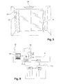
- Figure 5 a schematic representation of an entry and exit gantry of the location system according to the invention.
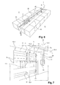
- Figure 6 an external view in 3 dimensions of a cold aisle inside which is installed a rail of the locating system according to the invention along which an antenna is able to move;
- Figure 7 a 3-dimensional interior view of the cold aisle of the Figure 6 ;
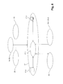
- Figure 8 a global functional schematic representation of the identification system according to the invention showing the interaction between the information system and the various elements of the system;
- Figure 9 a schematic representation of an encoding table of the system according to the invention for storing an identifier in the memory of the passive tags implemented in the invention.
- the Figures 1 and 2 show a cold aisle 1 of a computer room delimited by two rows 2.1, 2.2 of bays 3.
- Computer equipment 5 are installed horizontally or vertically inside the bays 3.
- the front faces of the equipment are positioned on the side of the cold aisle 1; while the rear faces at which the connections are made are positioned on the side of hot aisles 6 which separate the cold aisles 1 between them.
- the cold aisle 1 also includes a roof 8 generally made of plexiglass attached to the frames of the bays 3 ensuring the thermal insulation of the cold aisle 1.
- This roof 8 is separate from the ceiling or the false ceiling (not shown) of the room computer as such. 9 sliding doors also provide thermal insulation and access control to the computer room.
- the equipment 5 of the room are provided with labels 11.
- Each tag 11 containing in its memory identification information of the equipment 5 to which it corresponds.
- the labels 11 are preferably of the passive type. It is recalled that a passive tag is a battery-free tag activated by a solicitation signal transmitted by a fixed or mobile antenna.
- 12.1-12.4 also passive type tags are associated with one or more areas of each bay 3. These labels 12.1-12.4 contain information called "location" corresponding to these areas. In one example, using a first tag 12.1 to identify the bay 3, and three other tags 12.2-12.4 to identify the high and low areas of the bay and the intermediate area between these areas. As a variant, more or fewer labels 12.1-12.4 are used depending on the precision of the geographical grid sought.
- Antennas are used to read the identification or location information stored in tags 11 and 12.1-12.4.
- the antennas 14 are fixed on the roof 8 of the computer room.
- the antennas 14 are fixed using fastening means on the inner face of the roof 8 facing the interior of the computer room.
- the antennas 14 are simply placed on the face of the roof 8 facing the outside of the room, which saves mounting time.
- the roof 8 is made of a plexiglass-type material or any other type of material having equivalent properties, there is no problem of transmitting the signal of the antennas 14 inside the computer room.
- Each antenna 14 positioned between the rows of bays 3 covers a zone Z corresponding to four bays, namely two bays 3 facing each other (cf. Figure 1 ), which makes it possible to have a good efficiency in the reading of the various labels 11, 12.1-12.4.
- the antenna 14 covers two bays 3, namely one bay facing another bay.
- antennas 14 are associated with a reader 15 shown on the Figure 4 .
- four antennas 14 are associated with a reader 15.
- more or fewer than four antennas can be associated with the reader 15.
- This reader 15 is in connection with a management system 17 capable of displaying from the identification information and location information of the labels 11, 12.1-12.4, a graphical representation of the equipment 5 inside the different bays 3 .
- an antenna 18 carried by a rail 20 installed on the roof of the cold aisle 1 is used.
- the antenna 18 can move along this rail 20 to traverse all or part of a cold aisle 1.
- the speed of the antenna 18 on the rail 20 is of the order of 4 to 10 km / h.
- the rail 20 may have a rectilinear shape 22 or a form of a closed loop 22 'shown in phantom, preferably around the computer room.
- the antenna 18 covers an area corresponding to a single bay.
- the antenna 18 is connected to the rail 20 via an articulated arm 21 pivotable 23.1 along a vertical axis 24 (which lies in a plane substantially perpendicular to the floor of the room) to move from a first position wherein the antenna 18 is rotated toward a row of bays 3 at a second position in which the antenna 18 is rotated toward the opposite row of bays.
- the rotational movement of the arm 21 around the axis 24 thus makes it easy to scan both sides of a cold aisle 1.
- This embodiment is particularly advantageous in the case where the rail 20 has a rectilinear shape and a An antenna 18 scattering on one side is used.
- the arm 21 can move the antenna 18 (which covers only one side of an aisle) in translation 23.2 along the vertical axis 24, to allow optimal detection of the labels 11, 12.1-12.4 on all the height of the bays 3 of the computer room.
- an antenna 18 diffusing simultaneously to both sides of the cold aisle 1 is used.
- the arm 21 is pivotable 23.3 about a substantially horizontal axis 25 (which is substantially in a plane parallel to the floor of the computer room).
- the arm 21 can move from a vertical unfolded position in which it moves the antenna 18 along the rail 20 to a horizontal folded storage position.
- the antenna storage area is located substantially in the middle of a cold aisle 1.
- the system according to the invention may also include an antenna 28 installed on a gantry 29 positioned at the entrance of the computer room for detecting the entry and exit of equipment, especially servers, inside the computer room.
- a portable reader 30 (cf. Figure 2 ) equipped with an antenna
- the reading of the different labels 11, 12.1-12.4 is then performed by the movement of an operator in the computer room.
- a mobile carriage 32 equipped with a 32.1 antenna. This carriage 32 comprises means 32.2 for moving on the floor of the room and means 32.3 for moving in the vertical direction to read properly the labels located high in the room.
- a visual and / or audible signaling device 33 indicating that the antenna 14, 18 is in operation.
- This device 33 may for example control a blocking of the sliding doors 9 allowing access to the computer room.
- the labels 34.1-34.3 can be integrated in the labels 12.2-12.4.
- the labels 34.1-34.3 are preferably active, that is to say that they have their own power source and regularly transmit signals corresponding to their measurements to the antennas 14, 18.
- the labels 34.1 -34.3 are passive tags.
- the Figure 8 shows the interaction between the management system 17 and the readers 15 associated with automatic antennas 14, 18 and / or manual 30, and possibly also with the gantry 29, the environmental tags 34.1-34.3, and an external management software 35 .
- the system 17 is formed by an analysis software 17.1 in connection with a database 17.2 and a man / machine interface 17.3 allowing the user to submit his requests and to consult the answers provided by the system 17.
- the antennas 14, 18 transmit solicitation signals to the tags 11, 12.1-12.4 which respond by sending the identification information and location information received by the antennas 14, 18.
- the associated readers then transmit the information captured in the system 17 which then provides, via the interface 17.3, an indication preferably in graphic form of the positioning of the different equipment 5 in the computer room.
- the graphic representation has a granularity ranging from the computer room to a bay. This graphic representation shows the equipment 5 that the room or this bay contains. If necessary, the graphic representation of the computer room can be done in three dimensions.
- the user enters at least one of: the available space in each bay 3, the maximum power allowed for each bay 3, the number of available network connections for each bay 3, the number of taps electrical available for each bay 3, the weight of the equipment bearable by each bay 3.
- the user enters all of these parameters in the management system.
- the management system 17 From the identification and location information received by the antenna 14, 18, the management system 17 provides at least one indicator corresponding status among: the size of the equipment 5 installed in a bay 3 relative to the available space, the number of network connections used compared to the number of connections available, the number of electrical outlets used in relation to the number of electrical outlets available, the total weight of installed equipment.
- the identification information contained in the labels includes configuration parameters, namely: the size of the equipment 5, the number of network connections as well as the number of electrical outlets necessary for the operation of the equipment 5, and the energy consumption of the equipment 5. Alternatively, the user can enter this configuration information manually into the management system.
- the management system 17 acquires the configuration parameters of the new equipment 5 and offers the user the best location in the computer room for this new equipment, according to the configuration parameters of the new equipment 5.
- equipment and status indicators For example, the management system 17 proposes to install equipment consuming a lot in a bay near the source of cold; while proposing to install low-energy equipment in a bay far from this source.
- the system 17 will be able to display a map of the temperature level (and where appropriate humidity) in the computer room.
- Information transmitted by the external management software such as the level of consumption, will give a good visibility on the consumption at the desired granularity level (equipment alone, group of equipment forming a virtual server, bay, cold aisle, or room whole) and if necessary to propose solutions to reduce the consumption of equipment 5.
- the Figure 9 shows a schematic representation of an encoding table 37 of the system according to the invention for storing an identifier in the memory of the passive tags 11.
- the table 37 comprises an encoder 38, a touch-sensitive human-machine interface 39 Or other allowing the operator to select the identifier li from a list of identifiers l1-ln or to create the identifier from a calculation algorithm, and an isolation zone 40 to isolate the label 11 external disturbances to ensure the writing on the label 11.
- this area 40 is made from a bell 42 or a drawer 43 shown in dashed lines.
- a printing device 41 able to register visibly on the label 11 complementary information identical or not to the identifier.
- the character string "foo" is written label 11 will then be pasted on the corresponding equipment 5.
- the user can then establish in the database 17.2 a correlation between the identifier li assigned to the label and P parameters of the corresponding equipment 5.
- the P parameters of the equipment may consist of an indication of the model of the equipment and, in the case of a server, of the software that it executes.
Landscapes
- Business, Economics & Management (AREA)
- Engineering & Computer Science (AREA)
- Economics (AREA)
- Human Resources & Organizations (AREA)
- Operations Research (AREA)
- Accounting & Taxation (AREA)
- Finance (AREA)
- Development Economics (AREA)
- General Engineering & Computer Science (AREA)
- Entrepreneurship & Innovation (AREA)
- Computer Hardware Design (AREA)
- Marketing (AREA)
- Microelectronics & Electronic Packaging (AREA)
- Quality & Reliability (AREA)
- Strategic Management (AREA)
- Tourism & Hospitality (AREA)
- Physics & Mathematics (AREA)
- General Business, Economics & Management (AREA)
- General Physics & Mathematics (AREA)
- Theoretical Computer Science (AREA)
- Management, Administration, Business Operations System, And Electronic Commerce (AREA)
Applications Claiming Priority (1)
| Application Number | Priority Date | Filing Date | Title |
|---|---|---|---|
| FR1056452A FR2963680B1 (fr) | 2010-08-05 | 2010-08-05 | Systeme de localisation d'un equipement dans une salle informatique |
Publications (2)
| Publication Number | Publication Date |
|---|---|
| EP2416287A2 true EP2416287A2 (de) | 2012-02-08 |
| EP2416287A3 EP2416287A3 (de) | 2012-03-07 |
Family
ID=43707729
Family Applications (1)
| Application Number | Title | Priority Date | Filing Date |
|---|---|---|---|
| EP11175034A Withdrawn EP2416287A3 (de) | 2010-08-05 | 2011-07-22 | System zur Lokalisierung eines Geräts in einem Computerraum |
Country Status (2)
| Country | Link |
|---|---|
| EP (1) | EP2416287A3 (de) |
| FR (1) | FR2963680B1 (de) |
Cited By (2)
| Publication number | Priority date | Publication date | Assignee | Title |
|---|---|---|---|---|
| FR3057975A1 (fr) * | 2016-10-24 | 2018-04-27 | Uqode | Systeme d'automatisation d'inventaire utilisant des etiquettes radiofrequence. |
| CN116666942A (zh) * | 2023-06-01 | 2023-08-29 | 中国电信股份有限公司 | 射频分路切换器、射频识别系统及机房运维管理方法 |
Family Cites Families (6)
| Publication number | Priority date | Publication date | Assignee | Title |
|---|---|---|---|---|
| JP4745853B2 (ja) * | 2006-02-14 | 2011-08-10 | 富士通株式会社 | 在庫管理ロボットおよびそれによる在庫管理方法 |
| FR2905493B1 (fr) * | 2006-08-31 | 2008-12-05 | Nbg Id Soc Par Actions Simplif | Systeme automatise de realisation d'inventaires localises |
| US7857214B2 (en) * | 2007-04-26 | 2010-12-28 | Liebert Corporation | Intelligent track system for mounting electronic equipment |
| JP5037248B2 (ja) * | 2007-07-17 | 2012-09-26 | 株式会社日立製作所 | 情報収集システムおよび情報収集ロボット |
| US20090108995A1 (en) * | 2007-10-30 | 2009-04-30 | Commscope, Inc. | Equipment Mounting Systems and Methods for Identifying Equipment |
| US8063738B2 (en) * | 2008-02-04 | 2011-11-22 | Hewlett-Packard Development Company, L.P. | RFID system with a mobile RFID reader |
-
2010
- 2010-08-05 FR FR1056452A patent/FR2963680B1/fr not_active Expired - Fee Related
-
2011
- 2011-07-22 EP EP11175034A patent/EP2416287A3/de not_active Withdrawn
Non-Patent Citations (1)
| Title |
|---|
| None |
Cited By (2)
| Publication number | Priority date | Publication date | Assignee | Title |
|---|---|---|---|---|
| FR3057975A1 (fr) * | 2016-10-24 | 2018-04-27 | Uqode | Systeme d'automatisation d'inventaire utilisant des etiquettes radiofrequence. |
| CN116666942A (zh) * | 2023-06-01 | 2023-08-29 | 中国电信股份有限公司 | 射频分路切换器、射频识别系统及机房运维管理方法 |
Also Published As
| Publication number | Publication date |
|---|---|
| FR2963680A1 (fr) | 2012-02-10 |
| EP2416287A3 (de) | 2012-03-07 |
| FR2963680B1 (fr) | 2015-05-22 |
Similar Documents
| Publication | Publication Date | Title |
|---|---|---|
| US12265387B2 (en) | Building rooftop intelligence gathering and decision-support system and methods of augmented-reality supported building inspection | |
| US11565881B1 (en) | Mobile sortation and delivery of multiple items | |
| US10538190B1 (en) | Storage compartment vehicles | |
| EP4084993B1 (de) | Verbessertes system zur lieferung von vermögenswerten | |
| US10339491B2 (en) | Mobile pickup units | |
| US11127071B2 (en) | Drone station marketplace | |
| US10832017B2 (en) | Tracking objects in a two dimensional space | |
| KR20220137742A (ko) | 조정된 식사 배달 | |
| US20240127175A1 (en) | Methods, systems, and devices for beverage consumption and inventory control and tracking | |
| US10789569B1 (en) | System to determine item footprint | |
| WO2023183659A1 (en) | Method, platform, and system of electromagnetic marking of objects and environments for augmented reality | |
| US12492099B2 (en) | Methods and systems for delivering or accepting a parcel at a rooftop via an aerial vehicle | |
| US12001993B2 (en) | System and methods of electronics sampling to optimize system performance, cost, and confidence levels | |
| US20220318708A1 (en) | Coordinated delivery of dining experiences | |
| US20200394608A1 (en) | Intelligent vehicle delivery | |
| EP3281399A1 (de) | System zur auslösung des starts einer drohne nach feststellung eines ereignisses an einem bestimmten ort | |
| KR20170111708A (ko) | 저궤도 위성통신 기반의 벌크형 자재 관리 모니터링 장치 및 방법 | |
| EP2416287A2 (de) | System zur Lokalisierung eines Geräts in einem Computerraum | |
| US12169257B2 (en) | Industrial vehicle distance and range measurement device calibration | |
| FR3089660A1 (fr) | Appareil et systeme d'identification d'objets dans un local | |
| EP4276561B1 (de) | Autonome luftbildgebung und umgebungserfassung eines datencenters | |
| TW201545111A (zh) | 用於運送物品之無人飛行裝置及其方法 | |
| US20230073349A1 (en) | Methods, systems, and devices for beverage consumption and inventory control and tracking | |
| KR102478496B1 (ko) | 선박 운영 관리 시스템 | |
| JP7454608B2 (ja) | マテリアルハンドリング環境内の資産の場所を推定する方法及びシステム |
Legal Events
| Date | Code | Title | Description |
|---|---|---|---|
| PUAL | Search report despatched |
Free format text: ORIGINAL CODE: 0009013 |
|
| AK | Designated contracting states |
Kind code of ref document: A2 Designated state(s): AL AT BE BG CH CY CZ DE DK EE ES FI FR GB GR HR HU IE IS IT LI LT LU LV MC MK MT NL NO PL PT RO RS SE SI SK SM TR |
|
| AX | Request for extension of the european patent |
Extension state: BA ME |
|
| PUAI | Public reference made under article 153(3) epc to a published international application that has entered the european phase |
Free format text: ORIGINAL CODE: 0009012 |
|
| AK | Designated contracting states |
Kind code of ref document: A3 Designated state(s): AL AT BE BG CH CY CZ DE DK EE ES FI FR GB GR HR HU IE IS IT LI LT LU LV MC MK MT NL NO PL PT RO RS SE SI SK SM TR |
|
| AX | Request for extension of the european patent |
Extension state: BA ME |
|
| RIC1 | Information provided on ipc code assigned before grant |
Ipc: H05K 7/14 20060101ALI20120130BHEP Ipc: G06Q 10/00 20120101AFI20120130BHEP Ipc: G01R 31/28 20060101ALI20120130BHEP Ipc: G06K 17/00 20060101ALI20120130BHEP Ipc: B65G 1/137 20060101ALI20120130BHEP |
|
| 17P | Request for examination filed |
Effective date: 20120907 |
|
| 17Q | First examination report despatched |
Effective date: 20170220 |
|
| STAA | Information on the status of an ep patent application or granted ep patent |
Free format text: STATUS: THE APPLICATION IS DEEMED TO BE WITHDRAWN |
|
| 18D | Application deemed to be withdrawn |
Effective date: 20170704 |