EP2416436B1 - Elément de détection de tension et module de batterie comprenant ledit élément - Google Patents
Elément de détection de tension et module de batterie comprenant ledit élément Download PDFInfo
- Publication number
- EP2416436B1 EP2416436B1 EP10759006.9A EP10759006A EP2416436B1 EP 2416436 B1 EP2416436 B1 EP 2416436B1 EP 10759006 A EP10759006 A EP 10759006A EP 2416436 B1 EP2416436 B1 EP 2416436B1
- Authority
- EP
- European Patent Office
- Prior art keywords
- battery
- battery cells
- electrode terminal
- parts
- battery module
- Prior art date
- Legal status (The legal status is an assumption and is not a legal conclusion. Google has not performed a legal analysis and makes no representation as to the accuracy of the status listed.)
- Active
Links
Images




Classifications
-
- H—ELECTRICITY
- H01—ELECTRIC ELEMENTS
- H01M—PROCESSES OR MEANS, e.g. BATTERIES, FOR THE DIRECT CONVERSION OF CHEMICAL ENERGY INTO ELECTRICAL ENERGY
- H01M10/00—Secondary cells; Manufacture thereof
- H01M10/42—Methods or arrangements for servicing or maintenance of secondary cells or secondary half-cells
- H01M10/48—Accumulators combined with arrangements for measuring, testing or indicating the condition of cells, e.g. the level or density of the electrolyte
- H01M10/482—Accumulators combined with arrangements for measuring, testing or indicating the condition of cells, e.g. the level or density of the electrolyte for several batteries or cells simultaneously or sequentially
-
- H—ELECTRICITY
- H01—ELECTRIC ELEMENTS
- H01M—PROCESSES OR MEANS, e.g. BATTERIES, FOR THE DIRECT CONVERSION OF CHEMICAL ENERGY INTO ELECTRICAL ENERGY
- H01M10/00—Secondary cells; Manufacture thereof
- H01M10/42—Methods or arrangements for servicing or maintenance of secondary cells or secondary half-cells
- H01M10/48—Accumulators combined with arrangements for measuring, testing or indicating the condition of cells, e.g. the level or density of the electrolyte
-
- B—PERFORMING OPERATIONS; TRANSPORTING
- B60—VEHICLES IN GENERAL
- B60L—PROPULSION OF ELECTRICALLY-PROPELLED VEHICLES; SUPPLYING ELECTRIC POWER FOR AUXILIARY EQUIPMENT OF ELECTRICALLY-PROPELLED VEHICLES; ELECTRODYNAMIC BRAKE SYSTEMS FOR VEHICLES IN GENERAL; MAGNETIC SUSPENSION OR LEVITATION FOR VEHICLES; MONITORING OPERATING VARIABLES OF ELECTRICALLY-PROPELLED VEHICLES; ELECTRIC SAFETY DEVICES FOR ELECTRICALLY-PROPELLED VEHICLES
- B60L50/00—Electric propulsion with power supplied within the vehicle
- B60L50/50—Electric propulsion with power supplied within the vehicle using propulsion power supplied by batteries or fuel cells
- B60L50/60—Electric propulsion with power supplied within the vehicle using propulsion power supplied by batteries or fuel cells using power supplied by batteries
- B60L50/64—Constructional details of batteries specially adapted for electric vehicles
-
- G—PHYSICS
- G01—MEASURING; TESTING
- G01R—MEASURING ELECTRIC VARIABLES; MEASURING MAGNETIC VARIABLES
- G01R31/00—Arrangements for testing electric properties; Arrangements for locating electric faults; Arrangements for electrical testing characterised by what is being tested not provided for elsewhere
- G01R31/36—Arrangements for testing, measuring or monitoring the electrical condition of accumulators or electric batteries, e.g. capacity or state of charge [SoC]
- G01R31/385—Arrangements for measuring battery or accumulator variables
-
- H—ELECTRICITY
- H01—ELECTRIC ELEMENTS
- H01M—PROCESSES OR MEANS, e.g. BATTERIES, FOR THE DIRECT CONVERSION OF CHEMICAL ENERGY INTO ELECTRICAL ENERGY
- H01M50/00—Constructional details or processes of manufacture of the non-active parts of electrochemical cells other than fuel cells, e.g. hybrid cells
- H01M50/20—Mountings; Secondary casings or frames; Racks, modules or packs; Suspension devices; Shock absorbers; Transport or carrying devices; Holders
- H01M50/204—Racks, modules or packs for multiple batteries or multiple cells
-
- H—ELECTRICITY
- H01—ELECTRIC ELEMENTS
- H01M—PROCESSES OR MEANS, e.g. BATTERIES, FOR THE DIRECT CONVERSION OF CHEMICAL ENERGY INTO ELECTRICAL ENERGY
- H01M50/00—Constructional details or processes of manufacture of the non-active parts of electrochemical cells other than fuel cells, e.g. hybrid cells
- H01M50/20—Mountings; Secondary casings or frames; Racks, modules or packs; Suspension devices; Shock absorbers; Transport or carrying devices; Holders
- H01M50/271—Lids or covers for the racks or secondary casings
-
- H—ELECTRICITY
- H01—ELECTRIC ELEMENTS
- H01M—PROCESSES OR MEANS, e.g. BATTERIES, FOR THE DIRECT CONVERSION OF CHEMICAL ENERGY INTO ELECTRICAL ENERGY
- H01M50/00—Constructional details or processes of manufacture of the non-active parts of electrochemical cells other than fuel cells, e.g. hybrid cells
- H01M50/20—Mountings; Secondary casings or frames; Racks, modules or packs; Suspension devices; Shock absorbers; Transport or carrying devices; Holders
- H01M50/296—Mountings; Secondary casings or frames; Racks, modules or packs; Suspension devices; Shock absorbers; Transport or carrying devices; Holders characterised by terminals of battery packs
-
- H—ELECTRICITY
- H01—ELECTRIC ELEMENTS
- H01M—PROCESSES OR MEANS, e.g. BATTERIES, FOR THE DIRECT CONVERSION OF CHEMICAL ENERGY INTO ELECTRICAL ENERGY
- H01M50/00—Constructional details or processes of manufacture of the non-active parts of electrochemical cells other than fuel cells, e.g. hybrid cells
- H01M50/50—Current conducting connections for cells or batteries
- H01M50/502—Interconnectors for connecting terminals of adjacent batteries; Interconnectors for connecting cells outside a battery casing
- H01M50/503—Interconnectors for connecting terminals of adjacent batteries; Interconnectors for connecting cells outside a battery casing characterised by the shape of the interconnectors
-
- H—ELECTRICITY
- H01—ELECTRIC ELEMENTS
- H01M—PROCESSES OR MEANS, e.g. BATTERIES, FOR THE DIRECT CONVERSION OF CHEMICAL ENERGY INTO ELECTRICAL ENERGY
- H01M50/00—Constructional details or processes of manufacture of the non-active parts of electrochemical cells other than fuel cells, e.g. hybrid cells
- H01M50/50—Current conducting connections for cells or batteries
- H01M50/502—Interconnectors for connecting terminals of adjacent batteries; Interconnectors for connecting cells outside a battery casing
- H01M50/509—Interconnectors for connecting terminals of adjacent batteries; Interconnectors for connecting cells outside a battery casing characterised by the type of connection, e.g. mixed connections
- H01M50/51—Connection only in series
-
- H—ELECTRICITY
- H01—ELECTRIC ELEMENTS
- H01M—PROCESSES OR MEANS, e.g. BATTERIES, FOR THE DIRECT CONVERSION OF CHEMICAL ENERGY INTO ELECTRICAL ENERGY
- H01M50/00—Constructional details or processes of manufacture of the non-active parts of electrochemical cells other than fuel cells, e.g. hybrid cells
- H01M50/50—Current conducting connections for cells or batteries
- H01M50/531—Electrode connections inside a battery casing
- H01M50/534—Electrode connections inside a battery casing characterised by the material of the leads or tabs
-
- H—ELECTRICITY
- H01—ELECTRIC ELEMENTS
- H01M—PROCESSES OR MEANS, e.g. BATTERIES, FOR THE DIRECT CONVERSION OF CHEMICAL ENERGY INTO ELECTRICAL ENERGY
- H01M50/00—Constructional details or processes of manufacture of the non-active parts of electrochemical cells other than fuel cells, e.g. hybrid cells
- H01M50/50—Current conducting connections for cells or batteries
- H01M50/531—Electrode connections inside a battery casing
- H01M50/536—Electrode connections inside a battery casing characterised by the method of fixing the leads to the electrodes, e.g. by welding
-
- H—ELECTRICITY
- H01—ELECTRIC ELEMENTS
- H01M—PROCESSES OR MEANS, e.g. BATTERIES, FOR THE DIRECT CONVERSION OF CHEMICAL ENERGY INTO ELECTRICAL ENERGY
- H01M50/00—Constructional details or processes of manufacture of the non-active parts of electrochemical cells other than fuel cells, e.g. hybrid cells
- H01M50/50—Current conducting connections for cells or batteries
- H01M50/543—Terminals
-
- H—ELECTRICITY
- H01—ELECTRIC ELEMENTS
- H01M—PROCESSES OR MEANS, e.g. BATTERIES, FOR THE DIRECT CONVERSION OF CHEMICAL ENERGY INTO ELECTRICAL ENERGY
- H01M50/00—Constructional details or processes of manufacture of the non-active parts of electrochemical cells other than fuel cells, e.g. hybrid cells
- H01M50/50—Current conducting connections for cells or batteries
- H01M50/569—Constructional details of current conducting connections for detecting conditions inside cells or batteries, e.g. details of voltage sensing terminals
-
- H—ELECTRICITY
- H01—ELECTRIC ELEMENTS
- H01M—PROCESSES OR MEANS, e.g. BATTERIES, FOR THE DIRECT CONVERSION OF CHEMICAL ENERGY INTO ELECTRICAL ENERGY
- H01M50/00—Constructional details or processes of manufacture of the non-active parts of electrochemical cells other than fuel cells, e.g. hybrid cells
- H01M50/50—Current conducting connections for cells or batteries
- H01M50/572—Means for preventing undesired use or discharge
- H01M50/584—Means for preventing undesired use or discharge for preventing incorrect connections inside or outside the batteries
- H01M50/59—Means for preventing undesired use or discharge for preventing incorrect connections inside or outside the batteries characterised by the protection means
-
- G—PHYSICS
- G01—MEASURING; TESTING
- G01R—MEASURING ELECTRIC VARIABLES; MEASURING MAGNETIC VARIABLES
- G01R31/00—Arrangements for testing electric properties; Arrangements for locating electric faults; Arrangements for electrical testing characterised by what is being tested not provided for elsewhere
- G01R31/36—Arrangements for testing, measuring or monitoring the electrical condition of accumulators or electric batteries, e.g. capacity or state of charge [SoC]
- G01R31/364—Battery terminal connectors with integrated measuring arrangements
-
- H—ELECTRICITY
- H01—ELECTRIC ELEMENTS
- H01M—PROCESSES OR MEANS, e.g. BATTERIES, FOR THE DIRECT CONVERSION OF CHEMICAL ENERGY INTO ELECTRICAL ENERGY
- H01M2220/00—Batteries for particular applications
- H01M2220/20—Batteries in motive systems, e.g. vehicle, ship, plane
-
- H—ELECTRICITY
- H01—ELECTRIC ELEMENTS
- H01M—PROCESSES OR MEANS, e.g. BATTERIES, FOR THE DIRECT CONVERSION OF CHEMICAL ENERGY INTO ELECTRICAL ENERGY
- H01M50/00—Constructional details or processes of manufacture of the non-active parts of electrochemical cells other than fuel cells, e.g. hybrid cells
- H01M50/50—Current conducting connections for cells or batteries
- H01M50/502—Interconnectors for connecting terminals of adjacent batteries; Interconnectors for connecting cells outside a battery casing
- H01M50/505—Interconnectors for connecting terminals of adjacent batteries; Interconnectors for connecting cells outside a battery casing comprising a single busbar
-
- Y—GENERAL TAGGING OF NEW TECHNOLOGICAL DEVELOPMENTS; GENERAL TAGGING OF CROSS-SECTIONAL TECHNOLOGIES SPANNING OVER SEVERAL SECTIONS OF THE IPC; TECHNICAL SUBJECTS COVERED BY FORMER USPC CROSS-REFERENCE ART COLLECTIONS [XRACs] AND DIGESTS
- Y02—TECHNOLOGIES OR APPLICATIONS FOR MITIGATION OR ADAPTATION AGAINST CLIMATE CHANGE
- Y02E—REDUCTION OF GREENHOUSE GAS [GHG] EMISSIONS, RELATED TO ENERGY GENERATION, TRANSMISSION OR DISTRIBUTION
- Y02E60/00—Enabling technologies; Technologies with a potential or indirect contribution to GHG emissions mitigation
- Y02E60/10—Energy storage using batteries
-
- Y—GENERAL TAGGING OF NEW TECHNOLOGICAL DEVELOPMENTS; GENERAL TAGGING OF CROSS-SECTIONAL TECHNOLOGIES SPANNING OVER SEVERAL SECTIONS OF THE IPC; TECHNICAL SUBJECTS COVERED BY FORMER USPC CROSS-REFERENCE ART COLLECTIONS [XRACs] AND DIGESTS
- Y02—TECHNOLOGIES OR APPLICATIONS FOR MITIGATION OR ADAPTATION AGAINST CLIMATE CHANGE
- Y02T—CLIMATE CHANGE MITIGATION TECHNOLOGIES RELATED TO TRANSPORTATION
- Y02T10/00—Road transport of goods or passengers
- Y02T10/60—Other road transportation technologies with climate change mitigation effect
- Y02T10/70—Energy storage systems for electromobility, e.g. batteries
Definitions
- the present invention relates to a battery module comprising a voltage sensing member, and, more particularly, to a voltage sensing member for sensing voltages of battery cells constituting the battery module, the voltage sensing member including a pair of supporting parts, i.e., a front supporting part and a rear supporting part, mounted to a bottom of the battery module at regions (a front part and a rear part of the battery module) corresponding to electrode terminal connections of the battery cells, a connection part for electrically interconnecting the front supporting part and the rear supporting part, conductive sensing parts having one-side ends coupled to the corresponding supporting parts via wires, each of the conductive sensing parts having a larger contact surface than each of the wires, and a connector mounted on the front supporting part or the rear supporting part for transmitting the sensed voltages of the battery cells to a battery control device, wherein the conductive sensing parts are connected to the electrode terminal connections of the battery cells in a surface contact manner.
- a secondary battery which can be charged and discharged, has been widely used as an energy source for wireless mobile devices. Also, the secondary battery has attracted considerable attention as a power source for electric vehicles (EV) and hybrid electric vehicles (HEV), which have been developed to solve problems, such as air pollution, caused by existing gasoline and diesel vehicles using fossil fuels.
- EV electric vehicles
- HEV hybrid electric vehicles
- Small-sized mobile devices use one or several battery cells for each device.
- middle- or large-sized devices such as vehicles, use a middle- or large-sized battery module having a plurality of battery cells electrically connected to one another because high power and large capacity are necessary for the middle- or large-sized devices.
- the middle- or large-sized battery module is manufactured so as to have as small a size and weight as possible.
- a prismatic battery or a pouch-shaped battery which can be stacked with high integration and has a small weight to capacity ratio, is usually used as a battery cell of the middle- or large-sized battery module.
- much interest is currently focused on the pouch-shaped battery, which uses an aluminum laminate sheet as a sheathing member, because the weight of the pouch-shaped battery is small, the manufacturing costs of the pouch-shaped battery are low, and it is easy to modify the shape of the pouch-shaped battery.
- a battery module is a structural body including a plurality of battery cells which are combined with each other, with the result that the safety and the operating efficiency of the battery module may be lowered when overvoltage, overcurrent, and overheating occur in some of the battery cells. Consequently, a sensing unit for sensing the overvoltage, overcurrent, and overheating is needed.
- a voltage sensor is connected to the battery cells so as to sense and control the operation of the battery cells in real time or at predetermined time intervals.
- a secondary battery is being used as a power source for vehicles as a result of the extension of an application range of the secondary battery. For this reason, it is necessary to maintain a stably connected state of the sensing unit even when strong impact or vibration is applied to the secondary battery.
- bus bars are coupled to electrode leads of the battery cells by bolts at a predetermined torque.
- the bolts may be loosened due to external force such as vibration. Consequently, reflection and management of an optimum torque value are necessary so as to prevent the bolts from being loosened.
- stress is concentrated on electrode leads, which are relatively weak, and the electrode leads are fatigued, with the result that holes formed in electrode terminal connections such that the bolts are coupled through the holes may easily break.
- the mechanical coupling manner has a problem in that, when external force, such as vibration, is applied to a battery module, a sensing defect occurs due to loosening of the bolts, and, when external force is applied to the battery module, stress is concentrated on holes formed in the electrode terminals of the battery cells such that the bolts or the rivets are inserted through the holes, with the result that breakage of the holes occurs.
- sensing is performed by direct point contact between the electrode leads of the battery cells and the springs. That is, sensing through the overall surface is not performed but voltage of a corresponding battery cell is sensed using a specific point. In this point contact manner, however, the sensing surface may be separated due to external force, or foreign matter may be introduced between sensing parts, with the result that it may not be possible to perform stable voltage sensing.
- a voltage sensing member having a specific structure that is capable of performing stable sensing with respect to electrode leads of battery cells and a battery module including the same.
- An example of a voltage sensing member can be seen in WO 2007/102671 A .
- the described voltage sensing member is constructed in a structure in which linear mounting parts are mounted to supporting parts coupled to the bottom of a battery module, conductive sensing parts are mounted on the mounting parts while the conductive sensing parts are in elastic contact with electrode terminals of battery cells, and the sensing parts are electrically connected to a battery management system (BMS).
- BMS battery management system
- An example of a middle- or large-sized battery module is described in WO 2007/102670 A .
- the described battery module comprises a battery cell stack including a plurality of battery cells or unit modules electrically connected with each other, the battery cells or unit modules being erected in the lateral direction; a first module case constructed in a structure to entirely surround one side end of the battery cell stack and to partially surround the upper and lower ends of the battery cell stack, the first module case being provided at the front part thereof with external input and output terminals; a second module case coupled with the first module case, the second module case being constructed in a structure to entirely surround the other side end of the battery cell stack and to partially surround the upper and lower ends of the battery cell stack, the second module case being provided at the front part thereof with bus bars for connecting electrode terminals of the battery cell stack to the external input and output terminals; a sensing member mounted to the first module case or the second module case; and a battery management system (BMS) mounted to the first module case or the second module case, while being connected to the sensing member, for monitoring and controlling the operation of the battery module.
- BMS battery management system
- the present invention has been made to solve the above problems, and other technical problems that have yet to be resolved.
- a battery module comprising a voltage sensing member that is capable of stably sensing voltages of battery cells constituting a battery module even when external impact or frequent vibration is applied to the battery module during operation.
- a battery module including a battery cell stack comprising battery cells, and further comprising a voltage sensing member for sensing voltages of battery cells constituting the battery module, the voltage sensing member including (a) a pair of supporting parts, i.e., a front supporting part and a rear supporting part, mounted to a bottom of the battery module at regions (a front part and a rear part of the battery module) corresponding to electrode terminal connections of the battery cells, (b) a connection part for electrically interconnecting the front supporting part and the rear supporting part, (c) conductive sensing parts having one-side ends coupled to the corresponding supporting parts via wires, and (d) a connector mounted on the front supporting part or the rear supporting part for transmitting the sensed voltages of the battery cells to a battery control device, wherein the conductive sensing parts are connected to the electrode terminal connections of the battery cells in a surface contact manner.
- the conductive sensing parts are configured in a plate strip shape and the electrode terminal connections are bent perpendicularly in a direction in which ends of anode terminals of the battery cells facing cathode terminals of the battery cells face each other, wherein the cathode terminals are copper electrode leads, and the anode terminals are aluminum electrode leads (114).
- the cathode terminals are copper electrode leads
- the anode terminals are aluminum electrode leads (114).
- an end of each of the copper electrode leads is cut to a size corresponding to a size of each of the conductive sensing parts, and each of the copper electrode leads and a corresponding one of the conductive sensing parts are coupled to each of the aluminum electrode leads by welding.
- the conductive sensing parts are mounted at the front supporting part and the rear supporting part coupled to the lower end of the battery module such that the conductive sensing parts are electrically connected to the electrode terminal connections of the battery cells in a surface contact manner, with the result that it is possible to easily sense voltages of the battery cells more stably and reliably than in a point contact manner using springs.
- the voltage sensing member of the battery module according to the present invention it is not necessary to form additional coupling holes in the electrode terminal connections unlike a conventional mechanical coupling manner using bolts or nuts, and therefore, it is possible to prevent breakage of the electrode terminal connections due to external force.
- the surface contact manner described in the specification means a manner in which conductive sensing parts each having a larger contact surface than a wire are electrically connected to the outsides of the electrode terminal connections in a surface contact manner, not in a point or line contact manner.
- the conductive sensing parts have a smaller size than electrode terminal connections so as to achieve easy connection of the conductive sensing parts with respect to the electrode terminal connections, and a portion of each of the electrode terminal connections is cut to a size corresponding to the size of each of the conductive sensing parts.
- the electrode terminal connections mean series-connection regions between cathode terminals of battery. cells and anode terminals of neighboring battery cells. Portions of the cathode terminals or the anode terminals constituting the electrode terminal connections are cut, conductive sensing parts are located at the cut portions of the cathode terminals or the anode terminals, and the conductive sensing parts are connected to uncut portions of the electrode terminals in a surface contact manner, thereby achieving easier connection between the conductive sensing parts and the electrode terminal connections.
- Width and height of each of the conductive sensing parts may be selected within an appropriate range in which stable electrical connection between the cathode terminals and the anode terminals, which is an original function of the electrode terminal connections, is achieved, and, in addition, the conductive sensing parts are connected to the electrode terminal connections in a surface contact manner so as to stably sense voltages of the battery cells.
- each of the conductive sensing parts may have a width equivalent to 10 to 80 % of the width of each of the electrode terminal connections so as to achieve surface contact. If the width of each of the conductive sensing parts is less than 10 % of the width of each of the electrode terminal connections, it is difficult to stably sense voltages of the electrode terminals in a surface contact manner. On the other hand, if the width of each of the conductive sensing parts is greater than 80 % of the width of each of the electrode terminal connections, the size of each of the electrode terminal connections is excessively reduced, with the result that internal contact resistance between the cathode terminals and the anode terminals is increased, which is not preferable.
- each of the conductive sensing parts may have a height equivalent to 20 to 70 % of the height of each of the electrode terminal connections. If the height of each of the conductive sensing parts is less than 20 70 % of the height of each of the electrode terminal connections, it is difficult to stably sense voltages of the electrode terminals in a surface contact manner. On the other hand, if the height of each of the conductive sensing parts is greater than 70 % of the height of each of the electrode terminal connections, the size of each of the electrode terminal connections is excessively reduced, with the result that internal contact resistance between the cathode terminals and the anode terminals is increased, which is not preferable.
- Each of the conductive sensing parts may have a surface contact area with respect to a corresponding one of the electrode terminal connections equivalent to 30 to 60 % of a connection area (an area of an interface between a cathode terminals and a corresponding anode terminal) of each of the electrode terminal connections so as to achieve stable electrical connection between the cathode terminals and the anode terminals, which is an original function of the electrode terminal connections, as described above, and, at the same time, to stably sense voltages of the battery cells in a surface contact manner.
- one-side electrode terminal (a) is cut to a size corresponding to a size of each of the conductive sensing parts, and one-side electrode terminal (a) and a corresponding one of the conductive sensing parts are connected to the other-side electrode terminal (b) in a surface contact manner.
- one-side electrode terminal (a) is a cathode terminal
- a portion of the cathode terminal may be cut to a size corresponding to a size of each of the conductive sensing parts, and the remaining portion of the cathode terminal and a corresponding one of the conductive sensing parts may be connected to the other-side electrode terminal (b), i.e., an anode terminal with a predetermined contact surface.
- Connection between the conductive sensing parts and the electrode terminal connections is not particularly restricted as long as the connection between the conductive sensing parts and the electrode terminal connections is easily achieved.
- the connection between the conductive sensing parts and the electrode terminal connections may be achieved by welding. Since the conductive sensing parts and the electrode terminal connections are securely coupled to each other by welding, it is possible to reliably and stably sense the battery cells even when external force is applied to the battery cells.
- one-side electrode terminal (a) is cut to a size corresponding to a size of each of the conductive sensing parts, and one-side electrode terminal (a) and a corresponding one of the conductive sensing parts is connected to the other-side electrode terminal (b) in a surface contact manner as in the preferred example as previously described
- the front supporting part and the rear supporting part are plate-shaped members disposed at regions of the battery module corresponding to the electrode terminal connections of the battery cells, i.e., the bottoms of the front and rear parts of the battery module.
- the front supporting part and the rear supporting part serve to mechanically couple the conductive sensing parts and, at the same time, to electrically connect the conductive sensing parts to a battery control device, such as a battery management system (BMS).
- BMS battery management system
- the front supporting part and the rear supporting part are formed of a printed circuit board (PCB).
- the conductive sensing parts may be formed of a metal strip.
- the conductive sensing parts may be formed of a copper strip exhibiting high conductivity.
- the copper electrode leads which are anode terminals of the battery cells
- the conductive sensing parts which are copper strips
- the aluminum electrode leads which are cathode terminals of the battery cells
- An insulative protection film may be provided at a connection region between each of the conductive sensing parts and a corresponding one of the electrode terminal connections.
- the insulative protection film may be applied to or coated on the upper end of the connection region so as to secure corrosion resistance at the connection region and to prevent a sensing defect due to corrosion.
- the battery module may include (a) a battery cell stack including a plurality of battery cells or unit modules connected in series to each other in a state in which the battery cells or the unit modules stand in a lateral direction thereof, (b) an upper case configured in a structure to surround one side of the battery cell stack and to surround a portion of an upper end and a portion of a lower end of the battery cell stack, the upper case being provided at a front part thereof with external input and output terminals, (c) a lower case coupled to the upper case for surrounding the other side of the battery cell stack and surrounding a portion of the upper end and a portion of the lower end of the battery cell stack, the lower case being provided at a front part thereof with bus bars for connecting electrode terminals of the battery cells to the external input and output terminals, the voltage sensing member being mounted at a bottom of the lower case, and (d) a front cover mounted to the front part of the lower case for protecting connection regions between the electrode terminals of the battery cells and the bus bars from outside, the front cover
- a battery module including a plurality of battery cells
- the above-mentioned problem may be solved by the provision of a sensing member mounted along one of the cases, i.e., the upper case or the lower case, for sensing voltages of the battery cells in accordance with the present invention. That is, as described above, the sensing member may include sensing parts mounted in spaces defined on the front and rear parts of the lower case and a connection part for interconnecting the sensing parts. As described above, the sensing member may be a voltage sensing member. According to circumstances, a temperature sensing member may be further included.
- the voltage sensing member may be configured in a structure in which conductive sensing parts are mounted in spaces defined on the front and rear parts of the lower case such that the conductive sensing parts are coupled to electrode terminal connections, and a front supporting part, a rear supporting part and a connection part are mounted to the bottom of the lower case, whereby the electrical surface contact therebetween is stably maintained when external impact is applied to the battery module.
- the lower case may be provided at the bottom thereof with a depression into which the connection part is inserted, whereby the battery module is configured in a more compact structure.
- the depression may be provided at the inside thereof with a plurality of protrusions which are alternately oriented to stably fix the connection part inserted in the depression.
- the battery cell stack is mounted in the cases in such a manner that a plurality of battery cells or unit modules stand in the lateral direction thereof.
- regions of the battery cells or the unit modules where the electrode terminals of the battery cells or the unit modules protrude are defined as front and rear directions, and the opposite side edges of the battery cells or the unit modules are defined as a lateral direction. Consequently, the battery cell stack is configured in a structure in which the battery cells or the unit modules are erected such that one of the side edges of the battery cells or the unit modules stands with respect to the ground while the electrode terminals of the battery cells or the unit modules are oriented in the front and rear directions of the battery module.
- the battery cell stack includes a plurality of unit modules each including plate-shaped battery cells having electrode terminals formed at the upper and lower ends thereof, and each unit module includes two or more battery cells configured in a stacked structure in which electrode terminals of the battery cells are connected in series to each other and electrode terminal connections are bent such that the battery cells are stacked and a pair of high-strength cell covers configured to surround outsides of the battery cells excluding the electrode terminals of the battery cells when the cell covers are coupled with each other.
- the battery cells are connected in series and/or parallel with each other in each of the unit modules.
- a plurality of unit modules may be manufactured by coupling electrode terminals of the battery cells to each other, while arranging the battery cells in series in the longitudinal direction, such that the electrode terminals of the battery cells are successively adjacent to each other, bending the battery cells by twos or more such that the battery cells are stacked while being in tight contact with each other, and surrounding predetermined numbers of the stacked battery cells with the cell covers.
- the sequence of the manufacturing processes may be partially changed. For example, a plurality of unit modules may be manufactured, and then electrical connection between the unit modules may be performed.
- the battery cell stack in which the battery cells are stacked in high integration while the electrode terminals of the battery cells are connected with each other, may be vertically mounted in the separable upper and lower cases that are coupled with each other in the assembly-type coupling structure.
- the upper case and the lower case are configured in a structure in which the upper case and the lower case surround only the outer circumference of the battery cell stack, and therefore, most of the outside of the battery cell stack is exposed to the outside, so as to achieve easy dissipation of heat from the battery cell stack in a state in which the upper case and the lower case are coupled to each other. Consequently, as described above, the upper case is configured in a structure to surround one side of the battery cell stack and to surround a portion of an upper end and a portion of a lower end of the battery cell stack, and the lower case is configured in a structure to surround the other side of the battery cell stack and to surround a portion of the upper end and a portion of the lower end of the battery cell stack.
- the lower case is provided at the front part and a rear part thereof with spaces in which supporting parts and conductive sensing parts of the voltage sensing member are placed, and the conductive sensing parts are connected to portions of series-connection bent regions (electrode terminal connections) of the electrode terminals of the battery cells in a surface contact manner by welding.
- a plurality of unit modules may be manufactured by coupling electrode terminals of the battery cells to each other, while arranging the battery cells in series in the longitudinal direction, such that the electrode terminals of the battery cells are successively adjacent to each other, bending the battery cells by twos or more such that the battery cells are stacked while being in tight contact with each other, and surrounding predetermined numbers of the stacked battery cells with the cell covers, and then portions of the conductive sensing parts and the electrode terminal connections may be welded in a state in which the unit modules are mounted to the lower case.
- a plurality of unit modules may be manufactured by stacking two or more battery cells such that electrode terminals of the battery cells are adjacent to each other in a state in which the electrode terminals are not coupled to each other and surrounding predetermined numbers of the stacked battery cells with the cell covers, and then welding of the electrode terminal connections of the battery cells and welding of the conductive sensing parts and the electrode terminal connections may be simultaneously performed in a state in which the unit modules are mounted to the lower case.
- the number of processes for manufacturing the battery module is decreased, thereby reducing manufacturing costs.
- the upper case and the lower case may be provided in the insides thereof with pluralities of mounting grooves in which the outer circumferences of the battery cells or the unit modules are inserted.
- the cell covers of the respective unit modules are provided at the outer surfaces adjacent to the upper and lower ends thereof with steps of a predetermined size for easily fixing the respective unit modules, and the cell covers are provided at the outer surfaces adjacent to the opposite sides thereof with steps of a predetermined size for easily fixing the unit modules, such that the battery cell stack is stably mounted to the cases and the unit modules are stacked while being in tighter contact with each other, whereby the overall size of the battery cell stack is reduced.
- the mounting grooves of the upper and lower cases may be configured in a structure corresponding to the steps.
- the lower case is provided at the front part thereof with a pair of slits through which the outermost electrode terminals of the battery cell stack are inserted.
- the outermost electrode terminals of the battery cell stack are exposed through the slits and then bent such that the outermost electrode terminals of the battery cell stack are brought into tight contact with the front part of the lower case. Consequently, the outermost electrode terminals of the battery cell stack are more easily connected to the bus bars located at the front part of the lower case.
- a conductive member may be further mounted to at least one of the external input and output terminals for fixing the upper end of the front cover and assisting with the connection of a power cable necessary for electrical connection.
- the conductive member may include bent parts for elastically surrounding the power cable while being coupled to the external input and output terminals.
- the front cover may be further provided with holes for fixing a power cable. Insulative coupling members coupled to corresponding portions of the power cable may be inserted into the holes to fix the power cable.
- the front cover may be coupled to the lower case, for example, in an assembly coupling fashion.
- the upper and lower cases are coupled to each other in such a manner that the unit cell stack is mounted to one case (for example, the lower case), which is then coupled to the other case (for example, the upper case) in an assembly manner.
- the cases may be coupled to each other in various manners.
- the cases may be coupled to each other in a structure in which screws are threadedly engaged into threaded grooves formed at opposite sides of the cases or in a structure in which hooks are formed at one of the cases and coupling holes corresponding the hooks are formed at the other case such that the cases can be coupled to each other without using an additional member.
- the lower case is provided at the lower end of the front and/or the rear thereof with a coupling part protruding from the lower case such that the coupling part is fixed to an external device, the coupling part having a through hole formed in a center thereof.
- a battery control device such as a battery management system (BMS) connected to the voltage sensing member for monitoring and controlling the operation of the battery module may be mounted to the rear of the lower case.
- BMS battery management system
- the sensing parts of the voltage sensing member are mounted in the front and rear parts of the lower case, the sensing parts mounted in the rear part of the lower case are connected to the BMS mounted to the rear end of the rear part of the lower case, and the sensing parts mounted at the front part of the lower case are connected to the battery control device via the connection part mounted to the bottom of the lower case.
- the sensing member may include thermistors, as temperature sensing parts, mounted to the battery cells or the unit modules of the battery cell stack.
- the thermistors may be connected to the battery control device.
- a battery control device may be mounted to each battery module, or a battery control device may be mounted to a plurality of battery modules.
- the lower case may be integrally provided at the rear part thereof with a protruding battery control device receiving part in which the battery control device is integrally assembled, preferably the battery control device is received.
- the battery control device receiving part may be provided with a thermistor connector and a communication connector.
- Electrically insulative covers are further disposed on the outer surfaces of the supporting parts mounted to the bottom of the lower case, thereby increasing isolation of the supporting parts from the outside and improving a mechanical coupling degree between the supporting parts and the lower case.
- the middle- or large-sized battery module according to the present invention is generally configured in a compact structure, and the mechanical coupling and electrical connection of the middle- or large-sized battery module are stably accomplished without using a plurality of members. Also, it is possible to configure a battery module using a predetermined number of battery cells, for example, four, six, eight, or ten battery cells, thereby effectively installing a necessary number of battery modules in a limited space.
- a middle- or large-sized battery system having high power and large capacity, the battery system being configured by connecting a plurality of battery modules.
- the middle- or large-sized battery system according to the present invention may be manufactured by combining unit modules based on desired power and capacity.
- the battery system according to the present invention is preferably used as a power source for electric vehicles, hybrid electric vehicles, or plug-in hybrid electric vehicles, which have a limited installation space and are exposed to frequent vibration and strong impact in consideration of the installation efficiency and structural stability of the battery system as previously described.
- the voltage sensing member of the battery module according to the present invention is configured in a structure in which conductive sensing parts are connected to electrode terminal connections of battery cells in a surface contact manner, and therefore, it is possible to stably sense voltages of battery cells even when strong external impact or vibration is applied to the battery cells. Also, it is possible to easily manufacture a middle- or large-sized battery system having desired power and capacity using a battery module including the voltage sensing member of the battery module according to the present invention as a unit body.
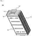
- FIG. 1 is a perspective view illustrating a battery cell stack constituted by a plurality of unit modules.
- a battery cell stack 100 includes four unit modules 101 and 130. Each of the unit modules 130 has two battery cells (not shown) mounted therein. Therefore, the battery cell stack 100 includes a total of eight battery cells. Electrode terminals between the respective battery cells are connected in series to each other, and electrode terminals between the respective unit modules are also connected in series to each other. Electrode terminal connections 110 are bent in a '[' shape in section to configure the battery cell stack. Outside electrode terminals 120 and 121 of the outermost unit modules 130 and 101 are bent inward in a '-' shape in section in a state in which the outside electrode terminals 120 and 121 protrude slightly more than the other electrode terminal connections 110.
- FIG. 2 is an exploded view illustrating upper and lower cases for surrounding the battery cell stack of FIG. 1 and a voltage sensing member.
- an upper case 200 is configured to surround one side of the battery cell stack 100 and to surround a portion of the upper end and a portion of the lower end of the battery cell stack 100.
- the upper case 200 is provided at the front part 210 thereof with a pair of external input and output terminals 220.
- the battery cell stack 100 is mounted in a lower case 300 in a state in which the unit modules 130 stand in the lateral direction thereof.
- the lower case 300 is coupled to the upper case 200 for surrounding the other side of the battery cell stack 100 and surrounding a portion of the upper end and a portion of the lower end of the battery cell stack 100.
- the lower case 300 is provided at the front part 310 thereof with a pair of bus bars 320 for connecting electrode terminals of the battery cell stack 100 to the external input and output terminals 220.
- the upper case 200 and the lower case 300 are configured in a structure in which the upper case 200 and the lower case 300 surround only the outer circumference of the battery cell stack 100, and therefore, most of the outside of the battery cell stack 100 is exposed to the outside, so as to achieve easy dissipation of heat from the battery cell stack 100 in a state in which the upper case 200 and the lower case 300 are coupled to each other.
- the bus bars 320 are configured such that upper ends of the bus bars 320 are formed in the shape of a depressed groove, into which the external input and output terminals 220, provided at the front part 210 of the upper case 200, are inserted when the upper case 200 and the lower case 300 are coupled to each other.
- the mounting grooves 330 are configured in a corresponding structure to which outer circumferential steps of the unit modules 130 are coupled.
- a plurality of through holes 230 and 332, through which a coolant (mainly, air) flows, are formed in the upper case 200 and the lower case 300 for achieving effective cooling in a state in which the battery cell stack 100 is mounted.
- a front cover 400 which is made of an insulative material, is mounted to the front part 310 of the lower case 300 for protecting connection regions between the electrode terminals of the battery cells and the bus bars from the outside.
- a conductive member 240 for fixing the upper end of the front cover 400 and assisting a power cable (not shown) for electrical connection to be mounted.
- the conductive member 240 is shown as being separated from one of the external input and output terminals 220 and being located in front of a corresponding one of the bus bars 320 in the drawing.
- the conductive member 240 is provided at one side thereof with a coupling insertion hole, into which a corresponding one of the external input and output terminals 220 is coupled.
- the conductive member 240 includes a pair of bent portions for elastically surrounding the power cable.
- holes 410 for fixing the power cable. Insulative coupling members (not shown) coupled to corresponding portions of the power cable are inserted into the holes 410 to fix the power cable.
- a pair of slits 322 through which outermost electrode terminals 120 and 121 of the battery cell stack 100 are inserted.
- the outermost electrode terminals 120 and 121 of the battery cell stack 100 are exposed through the slits 322, and then the outermost electrode terminals 120 and 121 of the battery cell stack 100 are bent such that the outermost electrode terminals 120 and 121 of the battery cell stack 100 come into contact with the front part 310 of the lower case 300.
- the outermost electrode terminals 120 and 121 of the battery cell stack 100 are more easily brought into contact with the bus bars 320 provided at the front part 310 of the lower case 300.
- a voltage sensing member 500 which is mounted at the bottoms of the front and rear parts of the lower case 300, includes a pair of supporting parts 510 and 512 mounted to the bottom of the lower case 300 at regions corresponding to the electrode terminal connections 110 of the battery cells or the unit modules, a wire-shaped connection part 520 for electrically interconnecting the supporting parts 510 and 512, plate strip type conductive sensing parts 531 having one-side ends coupled to the corresponding supporting parts 510 and 512 via wires 530, and insulative covers 561 and 562 mounted to the bottom of the voltage sensing member 500.
- the conductive sensing parts 531 are electrically connected to the lower ends of the electrode terminals of the battery cells and/or series-connection bent regions of the electrode terminals of the battery cells, i.e., the tops of the electrode terminal connections 110, by welding.
- the structure of the voltage sensing member 500 will be described in more detail with reference to FIGS. 5 to 7 .
- FIGS. 3 and 4 are partially enlarged plan views respectively illustrating upper and lower ends of a lower case of a middle- or large-sized battery module according to an embodiment of the present invention in a state in which unit modules are mounted in the lower case.
- the lower case 300 is provided at the insides of the front part 310 and the rear part 340 thereof with pluralities of fixing grooves 350 in which the electrode terminal connections 110 of the unit modules 130 and electrode terminal connections 170 of the battery cells mounted in the respective unit modules 130 are inserted.
- the fixing grooves 350 are formed approximately in a shape corresponding to the electrode terminal connections 110 and 170. Consequently, the fixing grooves 350 prevent the battery cell stack 100 from moving forward and rearward and maintain stable insulation between the neighboring electrode terminal connections.
- a cell cover movement preventing protrusion 352, a cell cover fixing guide 354, and an electrode terminal isolation wall 356 are formed in each of the fixing grooves 350 for achieving more stable fixing and insulation of the unit modules 130.
- the lower case 300 is provided at the lower end of the front part thereof with a coupling part 360 which protrudes from the lower case 300 and has a through-hole 362 in the center thereof such that the lower case 300 is fixed to an external device (not shown).
- a pair of protruding coupling parts 370 is formed at the lower end of the rear part of the lower case 300.
- One of the protruding coupling parts 370 i.e., a coupling parts 372 is formed such that the coupling part 372 is higher by a height equivalent to the thickness of the other protruding coupling part, i.e., a coupling parts 374, than the coupling part 374. Consequently, when a middle- or large-sized battery system is manufactured using a plurality of battery modules, the coupling between the battery modules is easily achieved, and the battery system is manufactured in a compact structure.
- the coupling parts 370 may be configured in various other structures different from the above structure.
- BMS 400 battery management system 400.
- the BMS 400 is received in a BMS receiving part 380 integrally formed at the lower case 300.
- a thermistor connector 382 and a communication connector 384 are mounted at the BMS receiving part 380.
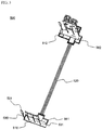
- FIG. 5 is a perspective view typically illustrating a voltage sensing member according to an embodiment of the present invention
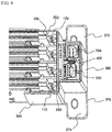
- FIG. 6 is a partial typical view illustrating a state in which the voltage sensing member according to the embodiment of the present invention is coupled to battery cells
- FIG. 7 is a typical view illustrating the bottom of a region A of FIG. 6 .
- the voltage sensing member 500 includes a front supporting part 510 and a rear supporting part 512 mounted to the bottom of the battery module 600 at regions corresponding to the electrode terminal connections 110 of the battery cells or the unit modules, a wire-shaped connection part 520 for electrically interconnecting the front supporting part 510 and a rear supporting part 512, pluralities of plate strip type conductive sensing parts 531 having one-side ends coupled to the corresponding supporting parts 510 and 512 via wires 530, each of the conductive sensing parts 531 having a larger contact surface than each of the wires 530, and electrically insulative covers 561 and 562 mounted to the bottoms of the BMS 400 mounted on the rear supporting part 512, the connector 384, and the voltage sensing member 500.
- a copper electrode lead 112 of each of the battery cells is cut to a size corresponding to the size of the conductive sensing parts 531, and the conductive sensing parts 531, formed of a copper strip, are coupled to an aluminum electrode lead 114 of each of the battery cells by welding.
- each of the conductive sensing parts 531 has a width w equivalent to approximately 60 % of the width W of each of the electrode terminal connections 110, and each of the conductive sensing parts 531 has a height h equivalent to approximately 50 % of the height H of each of the electrode terminal connections 110.
- each of the conductive sensing parts 531 has a surface contact area equivalent to approximately 43 % of the contact area of each of the electrode terminal connections 110.
- the width w and the height h of the conductive sensing parts 531 enable the conductive sensing parts 531 to be stably connected to the electrode terminal connections 110 of the battery cells. Even when external impact is applied to the battery module, electrical connection between the conductive sensing parts 531 and the electrode terminal connections 110 of the battery cells is stably maintained. Also, it is possible to sense voltages at the respective electrode terminals of the battery cells and/or the unit modules.
- the conductive sensing parts 531 which are formed of a copper strip, are connected to the aluminum electrode leads 114 together with the copper electrode leads 112 by welding, thereby achieving a two-layered welding structure, which exhibits higher weldability than a three-layered welding structure in which the copper electrode leads 112 and the conductive sensing parts 531 are sequentially stacked on the aluminum electrode leads 114.
- an insulative protection film 116 may be attached to the top of a connection region between each of the conductive sensing parts 531 and a corresponding one of the copper electrode leads 112 for preventing the connection region, which is formed by welding, from being corroded by foreign matter.
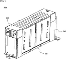
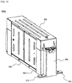
- FIGS. 8 to 10 are perspective views illustrating a middle- or large-sized battery pack according to an embodiment of the present invention.
- the conductive sensing parts 531 are connected to the BMS 400 via the wire type connection part 520 mounted to the lower end of the lower case 300.
- the lower case 300 is provided at the bottom 390 thereof with a depression 392 in which the connection part 520 is inserted.
- a plurality of protrusions 394 which are alternately oriented to stably fix the connection part 520 inserted in the depression 392.
- battery modules 600a and 600b are easily assembled by the coupling between the upper and lower cases 200 and 300.
- the BMS (not shown) is received in the BMS receiving part 380 integrally formed at the rear end of the rear part 340 of the lower case 300. Consequently, the battery modules 600a and 600b are configured in a simple and compact structure.
- the connection between the battery modules 600a and 600b may be achieved by coupling between a pair of coupling parts 372 and 374 formed at the lower end of the rear part 340 of the lower case 300 such that the pair of coupling parts 372 and 374 have different heights.
Landscapes
- Chemical & Material Sciences (AREA)
- Chemical Kinetics & Catalysis (AREA)
- Electrochemistry (AREA)
- General Chemical & Material Sciences (AREA)
- Engineering & Computer Science (AREA)
- Manufacturing & Machinery (AREA)
- Life Sciences & Earth Sciences (AREA)
- General Physics & Mathematics (AREA)
- Physics & Mathematics (AREA)
- Sustainable Development (AREA)
- Sustainable Energy (AREA)
- Power Engineering (AREA)
- Transportation (AREA)
- Mechanical Engineering (AREA)
- Connection Of Batteries Or Terminals (AREA)
- Battery Mounting, Suspending (AREA)
- Secondary Cells (AREA)
Claims (15)
- Module de batterie (600) incluant
une pile d'éléments de batterie (100) comprenant des éléments de batterie, et
un élément de détection de tension (500) détectant les tensions des éléments de batterie,
l'élément de détection de tension (500) incluant(a) une paire de parties de support (510, 512) comprenant une partie de support avant (510) et une partie de support arrière (512), montées sur un fond du module de batterie (600) dans des régions correspondant à des connexions de borne d'électrode (110) des éléments de batterie,(b) une partie de connexion (520) pour interconnecter électriquement la partie de support avant (510) et la partie de support arrière (512),(c) des parties de détection conductrices (531) ayant des extrémités de premier côté couplées aux parties de support correspondantes (510, 512) via des fils métalliques (530), et(d) un connecteur (384) monté sur la partie de support avant (510) ou sur la partie de support arrière (512) pour transmettre les tensions détectées des éléments de batterie à un dispositif de commande de batterie, caractérisé en ce queles parties de détection conductrices (531) sont connectées aux connexions de borne d'électrode (110) des éléments de batterie par un contact de surface,
les parties de détection conductrices (531) sont configurées en forme de ruban de tôle,
les connexions de borne d'électrode (110) sont recourbées perpendiculairement dans une direction dans laquelle les extrémités de bornes anodiques des éléments de batterie en regard de bornes cathodiques des éléments de batterie se font face les unes les autres,
les bornes cathodiques sont des câbles d'électrode en cuivre (112), et les bornes anodiques sont des câbles d'électrode en aluminium (114),
à chacune des connexions de borne d'électrode, une extrémité de chacun des câbles d'électrode en cuivre (112) est découpée à une taille correspondant à une taille de chacune des parties de détection conductrices (531), et chacun des câbles d'électrode en cuivre (112) et l'une correspondante des parties de détection conductrices (531) sont couplés à chacun des câbles d'électrode en aluminium (114) par soudage. - Module de batterie (600) selon la revendication 1, dans lequel chacune des parties de détection conductrices (531) a une largeur équivalant à 10 à 80 % d'une largeur de chacune des connexions de borne d'électrode (110).
- Module de batterie (600) selon la revendication 1, dans lequel chacune des parties de détection conductrices (531) a une hauteur équivalant à 20 à 70 % d'une hauteur de chacune des connexions de borne d'électrode (110).
- Module de batterie (600) selon la revendication 1, dans lequel chacune des parties de détection conductrices (531) a une surface de contact spécifique par rapport à l'une correspondante des connexions de borne d'électrode (110) équivalant à 30 à 60 % d'une zone de connexion de chacune des connexions de borne d'électrode (110).
- Module de batterie (600) selon la revendication 1, dans lequel, dans chacune des connexions de borne d'électrode (110), la borne d'électrode de premier côté (a) est découpée à une taille correspondant à une taille de chacune des parties de détection conductrices (531), et la borne d'électrode de premier côté (a) et l'une correspondante des parties de détection conductrices (531) sont connectées à la borne d'électrode d'autre côté (b) par un contact de surface.
- Module de batterie (600) selon la revendication 1, dans lequel la partie de support avant (510) et la partie de support arrière (512) sont formées d'une plaquette de circuits imprimés (PCB).
- Module de batterie (600) selon la revendication 1, dans lequel les parties de détection conductrices (531) sont formées d'un ruban de cuivre.
- Module de batterie (600) selon la revendication 1, dans lequel un film de protection isolant (116) est appliqué dans une région de connexion entre chacune des parties de détection conductrices (531) et l'une correspondante des connexions de borne d'électrode (110).
- Module de batterie (600) selon la revendication 1, dans lequel le module de batterie (600) inclut(a) la pile d'éléments de batterie (100) incluant une pluralité desdits éléments de batterie ou de modules unitaires (101, 130) connectés en série les uns avec les autres dans un état dans lequel les éléments de batterie ou les modules unitaires (101, 130) se situent dans une direction latérale de celle-ci,(b) une gaine supérieure (200) configurée dans une structure pour entourer un premier côté de la pile d'éléments de batterie (100) et pour entourer une partie d'une extrémité supérieure et une partie d'une extrémité inférieure de la pile d'éléments de batterie (100), la gaine supérieure (200) étant pourvue, dans sa partie avant, de bornes d'entrée et de sortie externes (220),(c) une gaine inférieure (300) couplée à la gaine supérieure (200) pour entourer l'autre côté de la pile d'éléments de batterie (100) et entourer une partie de l'extrémité supérieure et une partie de l'extrémité inférieure de la pile d'éléments de batterie (100), la gaine inférieure (300) étant pourvue, dans une partie avant de celle-ci, de barres omnibus (320) pour connecter les bornes d'électrode (120, 121) des éléments de batterie aux bornes d'entrée et de sortie externes (220), l'élément de détection de tension (500) étant monté sur le fond de la gaine inférieure (300), et(d) une coiffe avant (400) montée sur la partie avant de la gaine inférieure (300) pour protéger des régions de connexion entre les bornes d'électrode (120, 121) des éléments de batterie et les barres omnibus (320) de l'extérieur, la coiffe avant (400) étant constituée d'un matériau isolant.
- Module de batterie (600) selon la revendication 9, dans lequel l'élément de détection de tension (500) inclut les parties de détection conductrices (531) montées dans des espaces définis sur les parties avant et arrière de la gaine inférieure (300) de sorte que les parties de détection conductrices (531) soient couplées aux connexions de borne d'électrode (110), aux parties de support (510, 512), et à la partie de connexion (520), les parties de support (510, 512) et la partie de connexion (520) étant montées sur le fond de la gaine inférieure (300).
- Module de batterie (600) selon la revendication 9, dans lequel la pile d'éléments de batterie (100) inclut une pluralité de modules unitaires (101, 130) incluant chacun des éléments de batterie en forme de plaques ayant des bornes d'électrode (120, 121) formées à leurs extrémités supérieures et inférieures, et chaque module unitaire (101, 130) inclut deux éléments de batterie ou plus configurés en une structure empilée dans laquelle des bornes d'électrode (120, 121) des éléments de batterie sont connectées en série l'une avec l'autre et des connexions de borne d'électrode (110) sont recourbées de sorte que les éléments de batterie soient empilés et une paire de coiffes d'élément de grande résistance configurées pour entourer les extérieurs des éléments de batterie à l'exclusion des bornes d'électrode (120, 121) des éléments de batterie lorsque les coiffes des éléments sont couplées l'une à l'autre.
- Module de batterie (600) selon la revendication 9, dans lequel la gaine inférieure (300) est pourvue dans sa partie avant et sa partie arrière d'espaces dans lesquels des parties de support (510, 512) et des parties de détection conductrices (531) de l'élément de détection de tension (500) sont placées, et les parties de détection conductrices (531) sont connectées à des parties de régions recourbées à connexion en série des bornes d'électrode (120, 121) des éléments de batterie par contact de surface par soudage.
- Module de batterie (600) selon la revendication 9, dans lequel la gaine inférieure (300) est pourvue dans sa partie avant d'une paire de fentes à travers lesquelles les bornes d'électrode (120, 121) disposées le plus à l'extérieur de la pile d'éléments de batterie (100) sont insérées, et les bornes d'électrode (120, 121) disposées le plus à l'extérieur de la pile d'éléments de batterie (100) sont insérées à travers les fentes et connectées ensuite aux barres omnibus (320) situées dans la partie avant de la gaine inférieure (300).
- Module de batterie (600) selon la revendication 9, dans lequel la gaine inférieure (300) est pourvue dans sa partie arrière d'un dispositif de commande de batterie connecté à l'élément de détection de tension (500) pour contrôler et commander un fonctionnement du module de batterie.
- Système de batterie fabriqué comprenant le module de batterie selon la revendication 1 sous la forme d'un corps unitaire.
Applications Claiming Priority (2)
| Application Number | Priority Date | Filing Date | Title |
|---|---|---|---|
| KR20090027931 | 2009-04-01 | ||
| PCT/KR2010/001933 WO2010114281A2 (fr) | 2009-04-01 | 2010-03-30 | Elément de détection de tension et module de batterie comprenant ledit élément |
Publications (3)
| Publication Number | Publication Date |
|---|---|
| EP2416436A2 EP2416436A2 (fr) | 2012-02-08 |
| EP2416436A4 EP2416436A4 (fr) | 2015-09-16 |
| EP2416436B1 true EP2416436B1 (fr) | 2018-02-21 |
Family
ID=42828839
Family Applications (1)
| Application Number | Title | Priority Date | Filing Date |
|---|---|---|---|
| EP10759006.9A Active EP2416436B1 (fr) | 2009-04-01 | 2010-03-30 | Elément de détection de tension et module de batterie comprenant ledit élément |
Country Status (6)
| Country | Link |
|---|---|
| US (1) | US8329324B2 (fr) |
| EP (1) | EP2416436B1 (fr) |
| JP (1) | JP5355776B2 (fr) |
| KR (1) | KR101023921B1 (fr) |
| CN (1) | CN102379058B (fr) |
| WO (1) | WO2010114281A2 (fr) |
Families Citing this family (69)
| Publication number | Priority date | Publication date | Assignee | Title |
|---|---|---|---|---|
| JP5344932B2 (ja) | 2006-03-06 | 2013-11-20 | エルジー・ケム・リミテッド | 中型または大型電池モジュール |
| US9484591B2 (en) * | 2006-03-06 | 2016-11-01 | Lg Chem, Ltd. | Voltage sensing member and battery module employed with the same |
| KR100948002B1 (ko) | 2006-03-06 | 2010-03-18 | 주식회사 엘지화학 | 중대형 전지모듈 |
| WO2007102672A1 (fr) | 2006-03-06 | 2007-09-13 | Lg Chem, Ltd. | Module de batterie |
| JP5316008B2 (ja) * | 2009-01-14 | 2013-10-16 | ミツミ電機株式会社 | フューエルゲージ回路及びバッテリパック |
| KR101230954B1 (ko) * | 2010-04-08 | 2013-02-07 | 주식회사 엘지화학 | 신규한 구조의 센싱부재를 포함하는 전지모듈 |
| KR101217564B1 (ko) * | 2010-08-16 | 2013-01-02 | 주식회사 엘지화학 | 전압 검출 어셈블리 및 이를 포함하는 전지모듈 |
| EP2600440B1 (fr) * | 2011-04-18 | 2016-06-08 | Huawei Device Co., Ltd. | Batterie, composant de batterie et équipement utilisateur |
| KR101822612B1 (ko) * | 2011-04-27 | 2018-01-26 | 에스케이이노베이션 주식회사 | 전원차단이 용이한 배터리 모듈 |
| CN102790192A (zh) * | 2011-05-19 | 2012-11-21 | 鸿富锦精密工业(深圳)有限公司 | 电池座 |
| WO2013002507A2 (fr) | 2011-06-27 | 2013-01-03 | 주식회사 엘지화학 | Module de batterie et ensemble de batterie le comprenant |
| CN102956934B (zh) | 2011-08-17 | 2015-05-13 | 比亚迪股份有限公司 | 一种电池模组 |
| CN102385041B (zh) * | 2011-10-26 | 2014-06-18 | 杭州金色能源科技有限公司 | 电池芯检测装置 |
| US9494652B2 (en) * | 2012-01-31 | 2016-11-15 | Johnson Controls Technology Company | Voltage and temperature sensing of battery cell groups |
| DE102012205937A1 (de) * | 2012-04-12 | 2013-10-17 | Robert Bosch Gmbh | Sensorvorrichtung für einen elektrochemischen Energiespeicher, elektrochemischer Energiespeicher, Verfahren zum Herstellen einer Sensorvorrichtung für einen elektrochemischen Energiespeicher und Verfahren zum elektrischen Kontaktieren einer Sensorvorrichtung in einem elektrochemischen Energiespeicher |
| KR101924193B1 (ko) * | 2012-06-20 | 2018-12-03 | 에스케이이노베이션 주식회사 | 배터리 모듈 용접 방법 및 용접구조 |
| KR102050289B1 (ko) * | 2012-10-24 | 2020-01-08 | 에스케이이노베이션 주식회사 | 배터리 팩 |
| CN102969465A (zh) * | 2012-11-06 | 2013-03-13 | 上海航天电源技术有限责任公司 | 储能用绝缘减重结构一体化设计的锂离子电池模块 |
| WO2014078834A1 (fr) * | 2012-11-19 | 2014-05-22 | Aquion Energy Inc. | Dispositif et procédé pour interconnexion électrique de dispositif électrochimique |
| WO2014081221A1 (fr) | 2012-11-21 | 2014-05-30 | 주식회사 엘지화학 | Batterie secondaire au lithium |
| KR101558863B1 (ko) | 2012-11-21 | 2015-10-12 | 주식회사 엘지화학 | 리튬 이차전지 |
| KR102003067B1 (ko) * | 2012-12-21 | 2019-07-24 | 타이코에이엠피 주식회사 | 전압 센싱 모듈 및 이를 구비하는 전지모듈 |
| KR20140085890A (ko) * | 2012-12-28 | 2014-07-08 | 현대자동차주식회사 | 고전압 배터리팩용 배터리모듈 조립체 |
| KR101572447B1 (ko) * | 2013-03-19 | 2015-11-27 | 주식회사 엘지화학 | 전압 검출부재 및 이를 포함하는 전지모듈 |
| KR101717199B1 (ko) * | 2013-08-29 | 2017-03-16 | 주식회사 엘지화학 | 전압 센싱용 접속 돌기부가 형성되어 있는 전지셀 및 이를 포함하는 전지모듈 |
| CN105531847B (zh) * | 2013-09-11 | 2018-02-09 | 日本碍子株式会社 | 组合电池用容器 |
| KR101636380B1 (ko) * | 2013-09-26 | 2016-07-05 | 주식회사 엘지화학 | 전압 센싱 어셈블리 및 이를 포함하는 전지모듈 |
| KR101707976B1 (ko) * | 2013-10-29 | 2017-02-17 | 주식회사 엘지화학 | 개선된 체결구조를 갖는 센싱 모듈을 구비하는 배터리 모듈 |
| KR102258973B1 (ko) | 2013-10-31 | 2021-06-02 | 타이코에이엠피 주식회사 | 센싱 블록 및 이를 포함하는 배터리 패키지 |
| WO2015065078A1 (fr) * | 2013-10-31 | 2015-05-07 | 타이코에이엠피(유) | Bloc de détection et batterie le comprenant |
| KR101699865B1 (ko) * | 2013-12-17 | 2017-01-25 | 주식회사 엘지화학 | 직접 연결 방식의 전압 센싱부를 포함하는 전지모듈 |
| KR101667519B1 (ko) * | 2013-12-17 | 2016-10-28 | 주식회사 엘지화학 | 외부 입출력 단자를 형성하는 버스 바를 포함하는 전지모듈 |
| KR102150467B1 (ko) * | 2013-12-30 | 2020-09-01 | 에이치엘그린파워 주식회사 | 커버에 전압센싱부재가 설치된 배터리 모듈 |
| EP3002803B1 (fr) * | 2014-04-03 | 2019-07-03 | LG Chem, Ltd. | Série de modules de batterie |
| EP3128577B1 (fr) * | 2014-05-12 | 2019-09-04 | LG Chem, Ltd. | Bloc-batterie comportant un élément d'espacement |
| JP6394964B2 (ja) * | 2014-12-22 | 2018-09-26 | 株式会社オートネットワーク技術研究所 | 蓄電モジュール |
| KR101817237B1 (ko) * | 2014-12-24 | 2018-01-11 | 주식회사 엘지화학 | 이차전지 모듈의 전극 리드 용접 방법 및 이를 이용한 컴팩트한 이차전지 모듈 |
| KR101817236B1 (ko) | 2014-12-24 | 2018-01-11 | 주식회사 엘지화학 | 이차전지 모듈의 전극 리드 용접 방법 및 이를 이용한 컴팩트한 이차전지 모듈 |
| KR101808310B1 (ko) | 2014-12-24 | 2017-12-12 | 주식회사 엘지화학 | Bms 통합형 컴팩트 이차전지 모듈 |
| CN113381129B (zh) * | 2015-01-05 | 2024-03-29 | Cps科技控股有限公司 | 具有引导延伸部系统的蓄电池模块汇流条载体及方法 |
| US9620764B2 (en) * | 2015-01-05 | 2017-04-11 | Johnson Controls Technology Company | Battery module cooling fins and footings system and method |
| KR101884722B1 (ko) * | 2015-07-21 | 2018-08-02 | 주식회사 엘지화학 | 와이어 고정 리브들을 구비하고 있는 전지모듈 |
| KR102047482B1 (ko) * | 2015-10-30 | 2019-12-02 | 주식회사 엘지화학 | 배터리 모듈 및 이를 포함하는 배터리 팩 |
| KR102032506B1 (ko) * | 2016-06-08 | 2019-10-15 | 주식회사 엘지화학 | 센싱 와이어 하네스의 접속 구조가 개선된 배터리 모듈 및 그 조립방법 |
| TWM533365U (en) * | 2016-08-25 | 2016-12-01 | Formosa Electronic Ind Inc | Plug-in connection structure of stacked energy-storage battery module |
| KR102102927B1 (ko) | 2016-10-06 | 2020-04-21 | 주식회사 엘지화학 | 배터리 모듈, 이러한 배터리 모듈을 포함하는 배터리 팩 및 이러한 배터리 팩을 포함하는 자동차 |
| KR102204858B1 (ko) * | 2016-12-23 | 2021-01-19 | 에스케이이노베이션 주식회사 | 배터리 모듈 |
| JP6869355B2 (ja) * | 2016-12-27 | 2021-05-12 | ユラ・コーポレイション・カンパニー・リミテッドYura Corporation Co., Ltd. | 軟性回路基板及びこれを含むフレーム組立体 |
| US11376969B2 (en) | 2016-12-27 | 2022-07-05 | Yura Corporation Co., Ltd. | Bus bar assembly and frame assembly |
| WO2018124494A2 (fr) * | 2016-12-27 | 2018-07-05 | 주식회사 유라코퍼레이션 | Ensemble barre omnibus et ensemble cadre |
| KR102106344B1 (ko) | 2017-02-28 | 2020-05-04 | 주식회사 유라코퍼레이션 | 복수의 배터리 셀들의 과충전을 방지하기 위한 배터리 보호 모듈 및 배터리 모듈 |
| US10481215B2 (en) * | 2017-08-31 | 2019-11-19 | GM Global Technology Operations LLC | Method and apparatus for evaluating a battery cell |
| KR102161287B1 (ko) * | 2017-12-11 | 2020-09-29 | 삼성에스디아이 주식회사 | 배터리 팩 |
| IT201800002775A1 (it) | 2018-02-16 | 2019-08-16 | Ferrari Spa | Pacco batteria veicolare |
| IT201800002773A1 (it) * | 2018-02-16 | 2019-08-16 | Ferrari Spa | Pacco batteria veicolare |
| IT201800002774A1 (it) * | 2018-02-16 | 2019-08-16 | Ferrari Spa | Pacco batteria veicolare |
| KR102250204B1 (ko) * | 2018-03-07 | 2021-05-10 | 주식회사 엘지화학 | 배터리 모듈, 이러한 배터리 모듈을 포함하는 배터리 팩 및 이러한 배터리 팩을 포함하는 자동차 |
| KR101944111B1 (ko) * | 2018-04-24 | 2019-01-30 | 주식회사 경신 | 차량용 배터리 셀의 전압 측정장치 |
| KR102250193B1 (ko) * | 2018-10-10 | 2021-05-07 | 주식회사 엘지화학 | 공간 절약형 icb 조립체를 적용한 배터리 모듈 |
| KR102367381B1 (ko) * | 2018-12-26 | 2022-02-23 | 주식회사 엘지에너지솔루션 | 이물질 유입 방지 구조를 갖는 배터리 모듈, 이를 포함하는 배터리 팩 및 자동차 |
| KR102811566B1 (ko) | 2019-11-15 | 2025-05-22 | 주식회사 엘지에너지솔루션 | 외부 브릿지 버스바를 포함하는 고전압 전지모듈 |
| KR102151052B1 (ko) * | 2019-11-22 | 2020-09-02 | 에스케이이노베이션 주식회사 | 배터리 팩 |
| KR102903479B1 (ko) * | 2020-04-01 | 2025-12-22 | 삼성에스디아이 주식회사 | 배터리 팩 |
| KR102821825B1 (ko) * | 2020-07-22 | 2025-06-16 | 주식회사 엘지에너지솔루션 | 전극 리드와 전압 센싱부재 간의 연결을 단순화한 배터리 모듈 및 이를 포함하는 배터리 팩 |
| CN111948428B (zh) * | 2020-08-10 | 2023-05-26 | 南京莱迪新能源科技有限公司 | 一种新能源储能用锂离子电池在线快速检测电压的装置 |
| CN112349991B (zh) * | 2020-09-14 | 2022-03-18 | 比亚迪股份有限公司 | 一种电池储能装置 |
| KR20220043376A (ko) | 2020-09-29 | 2022-04-05 | 에이치그린파워 주식회사 | 배터리 모듈용 일체형 절연 커버 및 이를 포함한 배터리 모듈 |
| KR102815199B1 (ko) | 2021-04-15 | 2025-06-02 | 주식회사 엘지에너지솔루션 | 전지 셀 트레이 |
| KR20240040994A (ko) * | 2022-09-22 | 2024-03-29 | 에스케이온 주식회사 | 배터리 모듈 |
Family Cites Families (15)
| Publication number | Priority date | Publication date | Assignee | Title |
|---|---|---|---|---|
| JP3972884B2 (ja) * | 2003-10-10 | 2007-09-05 | 日産自動車株式会社 | 組電池 |
| JP4400234B2 (ja) * | 2004-02-03 | 2010-01-20 | 新神戸電機株式会社 | 組電池 |
| JP4690009B2 (ja) | 2004-10-22 | 2011-06-01 | 矢崎総業株式会社 | バッテリの電圧検出構造 |
| KR100801635B1 (ko) * | 2004-11-02 | 2008-02-05 | 주식회사 엘지화학 | 전지 팩의 전지 전압 및 온도 측정용 부재 |
| EP2450981B1 (fr) * | 2004-12-24 | 2014-03-19 | Lg Chem, Ltd. | Module de batterie secondaire |
| KR100891079B1 (ko) * | 2005-02-07 | 2009-03-30 | 주식회사 엘지화학 | 전지 모듈용 전지 카트리지 연결 시스템 |
| KR100896131B1 (ko) * | 2006-05-22 | 2009-05-08 | 주식회사 엘지화학 | 중대형 전지모듈 |
| JP5344932B2 (ja) * | 2006-03-06 | 2013-11-20 | エルジー・ケム・リミテッド | 中型または大型電池モジュール |
| KR100948002B1 (ko) | 2006-03-06 | 2010-03-18 | 주식회사 엘지화학 | 중대형 전지모듈 |
| US7875378B2 (en) * | 2006-03-06 | 2011-01-25 | Lg Chem, Ltd. | Voltage sensing member and battery module employed with the same |
| KR100884944B1 (ko) * | 2006-05-29 | 2009-02-23 | 주식회사 엘지화학 | 전압 검출부재 및 이를 포함하는 전지모듈 |
| JP5034273B2 (ja) * | 2006-03-07 | 2012-09-26 | トヨタ自動車株式会社 | 燃料電池 |
| JP5061698B2 (ja) * | 2006-07-19 | 2012-10-31 | トヨタ自動車株式会社 | 蓄電装置 |
| JP5176312B2 (ja) * | 2006-12-07 | 2013-04-03 | 日産自動車株式会社 | 組電池およびその製造方法 |
| JP5607684B2 (ja) * | 2012-07-09 | 2014-10-15 | 日本電気株式会社 | 組電池 |
-
2010
- 2010-03-30 KR KR1020100028412A patent/KR101023921B1/ko active Active
- 2010-03-30 EP EP10759006.9A patent/EP2416436B1/fr active Active
- 2010-03-30 WO PCT/KR2010/001933 patent/WO2010114281A2/fr not_active Ceased
- 2010-03-30 CN CN201080014969.4A patent/CN102379058B/zh active Active
- 2010-03-30 JP JP2012503321A patent/JP5355776B2/ja active Active
- 2010-08-06 US US12/851,876 patent/US8329324B2/en active Active
Non-Patent Citations (1)
| Title |
|---|
| None * |
Also Published As
| Publication number | Publication date |
|---|---|
| WO2010114281A2 (fr) | 2010-10-07 |
| KR101023921B1 (ko) | 2011-03-22 |
| US20110059342A1 (en) | 2011-03-10 |
| KR20100109857A (ko) | 2010-10-11 |
| JP2012523083A (ja) | 2012-09-27 |
| CN102379058A (zh) | 2012-03-14 |
| CN102379058B (zh) | 2014-06-18 |
| EP2416436A2 (fr) | 2012-02-08 |
| US8329324B2 (en) | 2012-12-11 |
| EP2416436A4 (fr) | 2015-09-16 |
| WO2010114281A3 (fr) | 2010-12-23 |
| JP5355776B2 (ja) | 2013-11-27 |
Similar Documents
| Publication | Publication Date | Title |
|---|---|---|
| EP2416436B1 (fr) | Elément de détection de tension et module de batterie comprenant ledit élément | |
| EP1991880B1 (fr) | Élément de détection de tension et module de batterie faisant intervenir cet élément | |
| US7892669B2 (en) | Middle or large-sized battery module | |
| EP1992026B1 (fr) | Module de batterie | |
| EP2538466B1 (fr) | Module de batterie comprenant des éléments de détection à structure innovatrice | |
| CN101395737B (zh) | 中型或大型电池模块 | |
| US8455122B2 (en) | Voltage sensing assembly for battery module and battery module employed with the same | |
| US9484591B2 (en) | Voltage sensing member and battery module employed with the same | |
| EP2416437B1 (fr) | Module batterie de moyenne ou grande taille à la sécurité améliorée | |
| US9972871B2 (en) | Voltage sensing member and battery module employed with the same | |
| US20100247979A1 (en) | Battery module interface | |
| JP6338905B2 (ja) | バッテリシステム |
Legal Events
| Date | Code | Title | Description |
|---|---|---|---|
| PUAI | Public reference made under article 153(3) epc to a published international application that has entered the european phase |
Free format text: ORIGINAL CODE: 0009012 |
|
| 17P | Request for examination filed |
Effective date: 20110929 |
|
| AK | Designated contracting states |
Kind code of ref document: A2 Designated state(s): AT BE BG CH CY CZ DE DK EE ES FI FR GB GR HR HU IE IS IT LI LT LU LV MC MK MT NL NO PL PT RO SE SI SK SM TR |
|
| DAX | Request for extension of the european patent (deleted) | ||
| A4 | Supplementary search report drawn up and despatched |
Effective date: 20150817 |
|
| RIC1 | Information provided on ipc code assigned before grant |
Ipc: B60L 11/18 20060101ALI20150811BHEP Ipc: G01R 31/36 20060101ALI20150811BHEP Ipc: H01M 2/10 20060101ALI20150811BHEP Ipc: H01M 2/20 20060101ALI20150811BHEP Ipc: H01M 10/48 20060101AFI20150811BHEP |
|
| 17Q | First examination report despatched |
Effective date: 20170124 |
|
| GRAP | Despatch of communication of intention to grant a patent |
Free format text: ORIGINAL CODE: EPIDOSNIGR1 |
|
| INTG | Intention to grant announced |
Effective date: 20171124 |
|
| GRAS | Grant fee paid |
Free format text: ORIGINAL CODE: EPIDOSNIGR3 |
|
| GRAA | (expected) grant |
Free format text: ORIGINAL CODE: 0009210 |
|
| AK | Designated contracting states |
Kind code of ref document: B1 Designated state(s): AT BE BG CH CY CZ DE DK EE ES FI FR GB GR HR HU IE IS IT LI LT LU LV MC MK MT NL NO PL PT RO SE SI SK SM TR |
|
| REG | Reference to a national code |
Ref country code: GB Ref legal event code: FG4D |
|
| REG | Reference to a national code |
Ref country code: CH Ref legal event code: EP |
|
| REG | Reference to a national code |
Ref country code: DE Ref legal event code: R096 Ref document number: 602010048642 Country of ref document: DE Ref country code: AT Ref legal event code: REF Ref document number: 972656 Country of ref document: AT Kind code of ref document: T Effective date: 20180315 |
|
| REG | Reference to a national code |
Ref country code: IE Ref legal event code: FG4D |
|
| REG | Reference to a national code |
Ref country code: FR Ref legal event code: PLFP Year of fee payment: 9 |
|
| REG | Reference to a national code |
Ref country code: NL Ref legal event code: MP Effective date: 20180221 |
|
| REG | Reference to a national code |
Ref country code: LT Ref legal event code: MG4D |
|
| REG | Reference to a national code |
Ref country code: AT Ref legal event code: MK05 Ref document number: 972656 Country of ref document: AT Kind code of ref document: T Effective date: 20180221 |
|
| PG25 | Lapsed in a contracting state [announced via postgrant information from national office to epo] |
Ref country code: CY Free format text: LAPSE BECAUSE OF FAILURE TO SUBMIT A TRANSLATION OF THE DESCRIPTION OR TO PAY THE FEE WITHIN THE PRESCRIBED TIME-LIMIT Effective date: 20180221 Ref country code: LT Free format text: LAPSE BECAUSE OF FAILURE TO SUBMIT A TRANSLATION OF THE DESCRIPTION OR TO PAY THE FEE WITHIN THE PRESCRIBED TIME-LIMIT Effective date: 20180221 Ref country code: FI Free format text: LAPSE BECAUSE OF FAILURE TO SUBMIT A TRANSLATION OF THE DESCRIPTION OR TO PAY THE FEE WITHIN THE PRESCRIBED TIME-LIMIT Effective date: 20180221 Ref country code: NL Free format text: LAPSE BECAUSE OF FAILURE TO SUBMIT A TRANSLATION OF THE DESCRIPTION OR TO PAY THE FEE WITHIN THE PRESCRIBED TIME-LIMIT Effective date: 20180221 Ref country code: NO Free format text: LAPSE BECAUSE OF FAILURE TO SUBMIT A TRANSLATION OF THE DESCRIPTION OR TO PAY THE FEE WITHIN THE PRESCRIBED TIME-LIMIT Effective date: 20180521 Ref country code: HR Free format text: LAPSE BECAUSE OF FAILURE TO SUBMIT A TRANSLATION OF THE DESCRIPTION OR TO PAY THE FEE WITHIN THE PRESCRIBED TIME-LIMIT Effective date: 20180221 Ref country code: ES Free format text: LAPSE BECAUSE OF FAILURE TO SUBMIT A TRANSLATION OF THE DESCRIPTION OR TO PAY THE FEE WITHIN THE PRESCRIBED TIME-LIMIT Effective date: 20180221 |
|
| PG25 | Lapsed in a contracting state [announced via postgrant information from national office to epo] |
Ref country code: LV Free format text: LAPSE BECAUSE OF FAILURE TO SUBMIT A TRANSLATION OF THE DESCRIPTION OR TO PAY THE FEE WITHIN THE PRESCRIBED TIME-LIMIT Effective date: 20180221 Ref country code: SE Free format text: LAPSE BECAUSE OF FAILURE TO SUBMIT A TRANSLATION OF THE DESCRIPTION OR TO PAY THE FEE WITHIN THE PRESCRIBED TIME-LIMIT Effective date: 20180221 Ref country code: GR Free format text: LAPSE BECAUSE OF FAILURE TO SUBMIT A TRANSLATION OF THE DESCRIPTION OR TO PAY THE FEE WITHIN THE PRESCRIBED TIME-LIMIT Effective date: 20180522 Ref country code: BG Free format text: LAPSE BECAUSE OF FAILURE TO SUBMIT A TRANSLATION OF THE DESCRIPTION OR TO PAY THE FEE WITHIN THE PRESCRIBED TIME-LIMIT Effective date: 20180521 Ref country code: AT Free format text: LAPSE BECAUSE OF FAILURE TO SUBMIT A TRANSLATION OF THE DESCRIPTION OR TO PAY THE FEE WITHIN THE PRESCRIBED TIME-LIMIT Effective date: 20180221 |
|
| RAP2 | Party data changed (patent owner data changed or rights of a patent transferred) |
Owner name: LG CHEM, LTD. |
|
| PG25 | Lapsed in a contracting state [announced via postgrant information from national office to epo] |
Ref country code: IT Free format text: LAPSE BECAUSE OF FAILURE TO SUBMIT A TRANSLATION OF THE DESCRIPTION OR TO PAY THE FEE WITHIN THE PRESCRIBED TIME-LIMIT Effective date: 20180221 Ref country code: EE Free format text: LAPSE BECAUSE OF FAILURE TO SUBMIT A TRANSLATION OF THE DESCRIPTION OR TO PAY THE FEE WITHIN THE PRESCRIBED TIME-LIMIT Effective date: 20180221 Ref country code: PL Free format text: LAPSE BECAUSE OF FAILURE TO SUBMIT A TRANSLATION OF THE DESCRIPTION OR TO PAY THE FEE WITHIN THE PRESCRIBED TIME-LIMIT Effective date: 20180221 Ref country code: RO Free format text: LAPSE BECAUSE OF FAILURE TO SUBMIT A TRANSLATION OF THE DESCRIPTION OR TO PAY THE FEE WITHIN THE PRESCRIBED TIME-LIMIT Effective date: 20180221 |
|
| REG | Reference to a national code |
Ref country code: CH Ref legal event code: PL |
|
| REG | Reference to a national code |
Ref country code: DE Ref legal event code: R097 Ref document number: 602010048642 Country of ref document: DE |
|
| PG25 | Lapsed in a contracting state [announced via postgrant information from national office to epo] |
Ref country code: SK Free format text: LAPSE BECAUSE OF FAILURE TO SUBMIT A TRANSLATION OF THE DESCRIPTION OR TO PAY THE FEE WITHIN THE PRESCRIBED TIME-LIMIT Effective date: 20180221 Ref country code: CZ Free format text: LAPSE BECAUSE OF FAILURE TO SUBMIT A TRANSLATION OF THE DESCRIPTION OR TO PAY THE FEE WITHIN THE PRESCRIBED TIME-LIMIT Effective date: 20180221 Ref country code: MC Free format text: LAPSE BECAUSE OF FAILURE TO SUBMIT A TRANSLATION OF THE DESCRIPTION OR TO PAY THE FEE WITHIN THE PRESCRIBED TIME-LIMIT Effective date: 20180221 Ref country code: SM Free format text: LAPSE BECAUSE OF FAILURE TO SUBMIT A TRANSLATION OF THE DESCRIPTION OR TO PAY THE FEE WITHIN THE PRESCRIBED TIME-LIMIT Effective date: 20180221 Ref country code: DK Free format text: LAPSE BECAUSE OF FAILURE TO SUBMIT A TRANSLATION OF THE DESCRIPTION OR TO PAY THE FEE WITHIN THE PRESCRIBED TIME-LIMIT Effective date: 20180221 |
|
| REG | Reference to a national code |
Ref country code: BE Ref legal event code: MM Effective date: 20180331 |
|
| REG | Reference to a national code |
Ref country code: IE Ref legal event code: MM4A |
|
| PLBE | No opposition filed within time limit |
Free format text: ORIGINAL CODE: 0009261 |
|
| STAA | Information on the status of an ep patent application or granted ep patent |
Free format text: STATUS: NO OPPOSITION FILED WITHIN TIME LIMIT |
|
| PG25 | Lapsed in a contracting state [announced via postgrant information from national office to epo] |
Ref country code: LU Free format text: LAPSE BECAUSE OF NON-PAYMENT OF DUE FEES Effective date: 20180330 |
|
| 26N | No opposition filed |
Effective date: 20181122 |
|
| PG25 | Lapsed in a contracting state [announced via postgrant information from national office to epo] |
Ref country code: IE Free format text: LAPSE BECAUSE OF NON-PAYMENT OF DUE FEES Effective date: 20180330 |
|
| PG25 | Lapsed in a contracting state [announced via postgrant information from national office to epo] |
Ref country code: SI Free format text: LAPSE BECAUSE OF FAILURE TO SUBMIT A TRANSLATION OF THE DESCRIPTION OR TO PAY THE FEE WITHIN THE PRESCRIBED TIME-LIMIT Effective date: 20180221 Ref country code: CH Free format text: LAPSE BECAUSE OF NON-PAYMENT OF DUE FEES Effective date: 20180331 Ref country code: LI Free format text: LAPSE BECAUSE OF NON-PAYMENT OF DUE FEES Effective date: 20180331 Ref country code: BE Free format text: LAPSE BECAUSE OF NON-PAYMENT OF DUE FEES Effective date: 20180331 |
|
| PG25 | Lapsed in a contracting state [announced via postgrant information from national office to epo] |
Ref country code: MT Free format text: LAPSE BECAUSE OF NON-PAYMENT OF DUE FEES Effective date: 20180330 |
|
| PG25 | Lapsed in a contracting state [announced via postgrant information from national office to epo] |
Ref country code: TR Free format text: LAPSE BECAUSE OF FAILURE TO SUBMIT A TRANSLATION OF THE DESCRIPTION OR TO PAY THE FEE WITHIN THE PRESCRIBED TIME-LIMIT Effective date: 20180221 |
|
| PG25 | Lapsed in a contracting state [announced via postgrant information from national office to epo] |
Ref country code: PT Free format text: LAPSE BECAUSE OF FAILURE TO SUBMIT A TRANSLATION OF THE DESCRIPTION OR TO PAY THE FEE WITHIN THE PRESCRIBED TIME-LIMIT Effective date: 20180221 Ref country code: HU Free format text: LAPSE BECAUSE OF FAILURE TO SUBMIT A TRANSLATION OF THE DESCRIPTION OR TO PAY THE FEE WITHIN THE PRESCRIBED TIME-LIMIT; INVALID AB INITIO Effective date: 20100330 |
|
| PG25 | Lapsed in a contracting state [announced via postgrant information from national office to epo] |
Ref country code: MK Free format text: LAPSE BECAUSE OF NON-PAYMENT OF DUE FEES Effective date: 20180221 |
|
| PG25 | Lapsed in a contracting state [announced via postgrant information from national office to epo] |
Ref country code: IS Free format text: LAPSE BECAUSE OF FAILURE TO SUBMIT A TRANSLATION OF THE DESCRIPTION OR TO PAY THE FEE WITHIN THE PRESCRIBED TIME-LIMIT Effective date: 20180621 |
|
| P01 | Opt-out of the competence of the unified patent court (upc) registered |
Effective date: 20230408 |
|
| REG | Reference to a national code |
Ref country code: DE Ref legal event code: R081 Ref document number: 602010048642 Country of ref document: DE Owner name: LG ENERGY SOLUTION, LTD., KR Free format text: FORMER OWNER: LG CHEM. LTD., SEOUL, KR |
|
| REG | Reference to a national code |
Ref country code: GB Ref legal event code: 732E Free format text: REGISTERED BETWEEN 20230824 AND 20230831 |
|
| PGFP | Annual fee paid to national office [announced via postgrant information from national office to epo] |
Ref country code: GB Payment date: 20260224 Year of fee payment: 17 |
|
| PGFP | Annual fee paid to national office [announced via postgrant information from national office to epo] |
Ref country code: DE Payment date: 20260220 Year of fee payment: 17 |
|
| PGFP | Annual fee paid to national office [announced via postgrant information from national office to epo] |
Ref country code: FR Payment date: 20260224 Year of fee payment: 17 |