EP2417331B1 - Mesure du débit de la boue de forage dans un espace annulaire pour détecter des disfonctionnements dans le trou de forage - Google Patents
Mesure du débit de la boue de forage dans un espace annulaire pour détecter des disfonctionnements dans le trou de forage Download PDFInfo
- Publication number
- EP2417331B1 EP2417331B1 EP10713278.9A EP10713278A EP2417331B1 EP 2417331 B1 EP2417331 B1 EP 2417331B1 EP 10713278 A EP10713278 A EP 10713278A EP 2417331 B1 EP2417331 B1 EP 2417331B1
- Authority
- EP
- European Patent Office
- Prior art keywords
- well
- measuring
- caliper
- acoustic
- velocity
- Prior art date
- Legal status (The legal status is an assumption and is not a legal conclusion. Google has not performed a legal analysis and makes no representation as to the accuracy of the status listed.)
- Not-in-force
Links
Images



Classifications
-
- E—FIXED CONSTRUCTIONS
- E21—EARTH OR ROCK DRILLING; MINING
- E21B—EARTH OR ROCK DRILLING; OBTAINING OIL, GAS, WATER, SOLUBLE OR MELTABLE MATERIALS OR A SLURRY OF MINERALS FROM WELLS
- E21B47/00—Survey of boreholes or wells
- E21B47/10—Locating fluid leaks, intrusions or movements
-
- E—FIXED CONSTRUCTIONS
- E21—EARTH OR ROCK DRILLING; MINING
- E21B—EARTH OR ROCK DRILLING; OBTAINING OIL, GAS, WATER, SOLUBLE OR MELTABLE MATERIALS OR A SLURRY OF MINERALS FROM WELLS
- E21B47/00—Survey of boreholes or wells
- E21B47/08—Measuring diameters or related dimensions at the borehole
Definitions
- the present disclosure relates in general to methods of drilling wellbores, for example, but not limited to, wellbores for producing hydrocarbons from subterranean formations, and more particularly to methods of measuring annulus drilling mud flow rate, either during drilling of a wellbore or during periods of fluid flow only.
- GB 2399111A discloses a method of determining volumetric flow rate in an annulus past one or more points in an unbalanced drilling well environment comprising selectively activating a first fluid flowing from the formation through a wellbore which under balanced drilled; detecting the first fluid; and determining a depth at which said fluid enters the wellbore, wherein the tool for determining flow has an activation device (6) and a gamma ray detector (7) separated along a drill string axis thereof by a distance d; the tool further including control circuitry for activating the device, activating the first fluid, processing means responsive to the gamma ray detector and to calculate the depth at which the fluid is detected.
- the '163 patent mentions that by operating transducers at multiple frequencies, fewer transducers are needed to generate frequency dependence data.
- a system might include a "1 MHz transducer” operated at 1 MHz and 3 MHz and a "9 MHz transducer” operated at 9 MHz and 27 MHz.
- speed of sound in the fluid can be calculated by measuring the time of flight of the pulse over the known distance between a transmitter and receiver.
- the receiver may also be used to determine the attenuation coefficient of the fluid, preferably at multiple frequencies (including third harmonics), by measuring the decay of multiple reflected signals, or comparing the transmitted signals to those of a fluid with known attenuation coefficient.
- apparatus may use ultrasonic signals to measure rheological properties of a fluid flow such as, e.g., the consistency index K, the flow behavior index n', the yield stress, or other parameters of any given model for shear rate dependent viscosity.
- the method includes: (a) transmitting an acoustic signal into the fluid flow; (b) receiving acoustic reflections from acoustic reflectors entrained in the fluid flow; (c) determining a Doppler shift of the acoustic reflections in a set of time windows corresponding to a set of desired sampling regions in the fluid flow; and (d) analyzing the Doppler shifts associated with the set of sampling regions to determine one or more rheological properties of the fluid flow.
- the frequency shift caused by motion of the fluid is proportional to the velocity of the fluid, and this allows the construction of a velocity profile of the fluid flow stream.
- Drill pipe is not normally centralized above the bottom hole assembly. Ex-centralization of the drillpipe will lead to variations in the annular velocity around the pipe. Detectors aimed in different radial directions will detect different velocities.
- flow rate means volumetric flow rate (volume/time) of all material flowing past a particular point in a well.
- “Caliper” means the shortest distance from the drill pipe outer diameter to the wellbore wall in a plane substantially perpendicular to the drill pipe.
- “Standoff”, a term frequently used in this area, means the shortest distance between a measuring device (or a component thereof) and the wellbore wall in a plane substantially perpendicular to the drill pipe.
- "During drilling” means an action is being performed involving a transformation of a subterranean well to a different state. This transformation may be, for example, but not limited to, transformation of solid rock to granular rock while the well is actually being drilled with a drill pipe, a drill bit attached to the drill pipe, and a flowing drilling mud.
- the transformation of the subterranean well to a different state may involve one or more well interventions to remediate those events prior to allowing actual drilling to continue, to safely circulate and continue to convert solid rock to granular rock.
- a first aspect of the disclosure is a method of determining volumetric flow rate of material (which may comprise drilling mud, chemicals, rocks, and the like) in an annulus past one or more points in a well, the method comprising:
- Exemplary methods of this disclosure use the determined total volumetric flow rate to locate a point or points of dysfunction in the well. Further methods in accordance with this disclosure use the information on the point or points of well dysfunction to diagnose root cause of the well dysfunction. In yet further exemplary embodiments, once the root cause of the well dysfunction is diagnosed, certain methods of this disclosure comprise selecting an appropriate well treatment, and placing the well treatment where the well dysfunction has developed in the well. In certain methods of this disclosure, all steps may occur during drilling, but this is not necessarily so. For example, the "computing" and “summing" steps may occur at some later time, after the measuring steps. Even if all steps occur during drilling, the steps may or may not occur at the same time.
- the measurements of caliper or standoff, and/or physical velocity of the mud may be made at a single point or distributed at a plurality of points along the drill pipe. Since flow will vary around the well as a result of excentralization of the drill pipe and/or gravity effects upon entrained solids in deviated wells, dividing up the well annulus into segments allows characterization of the flow velocity around the well. In certain embodiments, measuring velocity of sound in the mud in or substantially near at least a substantial number of the segments using a time of flight measurement between two points separated by a known distance may be used to improve the distance measurements, the velocity measurements, or both.
- Measurement of caliper is not limited to acoustic methods.
- the hole size might also be measured using mechanical, electromagnetic, gamma, or rotational density methods. There will undoubtedly be other methods as well.
- Caliper or standoff may be measured using any caliper or standoff measuring techniques which are already described in the literature and understood by those in the art. For example, one common method used is the acoustic pulse echo technique described by Zemanek in his 1990 SPWLA paper, referred to in the Background.
- the velocity of sound measurement may be used to more accurately calculate the distance from a pulse echo measurement as may have been done in step (a), and may also be used to improve an acoustic physical mud velocity measurement in step (b), although the physical velocity of the mud may be measured by methods other than acoustic. Time of flight would be one way to measure the physical velocity of the mud. Physical velocity of the mud could also be measured using Doppler or sonar methods, or mechanical or neutron activation or any other number of other methods to measure physical velocity.
- U.S. Pat. No. 6,725,162 summarizes various electromagnetic caliper measurement techniques, such as U.S. Pat. No. 4,899,112 , which describes a technique for determining a borehole caliper by comparing phase differences and attenuation levels from electromagnetic measurements.
- U.S. Pat. No. 5,900,733 discloses a technique for determining borehole diameters by examining the phase shift, phase average, and attenuation of signals from multiple transmitter and receiver locations via electromagnetic wave propagation.
- GB 2187354 A and U.S. Pat. No. 5,519,668 also describe while-drilling methods for determining a borehole size using electromagnetic signals.
- 5,091,644 describes a method for obtaining a borehole size measurement as a by-product of a rotational density measurement while drilling.
- U.S. Pat. No. 6,285,026 describes a LWD technique for determining the borehole diameter through neutron porosity measurements.
- the method further comprises measuring temperature and annular fluid pressure in each segment, and calculating temperature- and pressure-corrected caliper or standoff using the measured temperature and annular fluid pressure in each segment. In embodiments wherein the velocities are measured acoustically, these corrections may also be applied to some or all of the physical velocity measurements.
- the method comprises using the determined volumetric flow rate to reliably locate a point of lost circulation, a well fluid influx, or other dysfunction in the well.
- the information on location of well dysfunction may be used to diagnose the root cause of the well dysfunction.
- the method comprises selecting an appropriate treatment, and placing a well treatment where the dysfunction has developed in the well.
- Another aspect of the invention is an apparatus for determining flow rate of material at one or more points downhole in a wellbore annulus, comprising:
- Certain embodiments may include a sensor for measuring the velocity of sound in the mud near at least some of the sensors using a time of flight measurement between one or more transmitter/receiver pairs. Certain other embodiments may include temperature and pressure measuring sensors in the segments for measuring temperature and pressure in the segments and using the temperatures and pressures to correct acoustic measurements.
- caliper and fluid velocity measurements can be combined to determine the actual volumetric flow rate in the annulus past a point in a well, allowing integration of the fluid velocity as a function of the hole size around the well to account for pipe position.
- Methods and apparatus described herein provide true volumetric flow rate during drilling which may then be used to reliably find a point of lost circulation, a well fluid influx, or other well dysfunction, which then allows for correct diagnosis of the root cause, selection of the appropriate treatment and placement of that treatment where the problem has developed in the well.
- Methods and apparatus of the invention are applicable to both on-shore (land-based) and offshore (subsea-based) drilling.
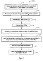
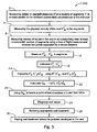
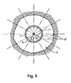
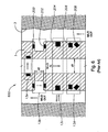
- FIGS. 1-3 illustrate three method embodiments of the present disclosure in flowchart form, using the terminology presented in FIGS. 4 and 5 .
- FIGS. 4 and 5 these simplified schematic diagrams illustrate mud flowing through a drill pipe 1 generally downward at an axial velocity VM 1 , where the "1" designates flow inside the drill pipe.
- Drill pipe 1, or a portion thereof (such as a drill collar) rotates, as indicated by the circular arrow.
- a drill bit is not illustrated, but would be attached to a lower portion of drill pipe 1.
- the mud flows downward and exits through the drill bit, carrying rock cuttings generally upward in an annulus defined between an outer surface of drill pipe 1 and bore hole 3.
- drill pipe 1 is depicted as generally constant diameter, while bore hole 3 has an irregular shape, as depicted in FIGS. 4 and 5 .
- the mixture velocity (hereinafter referred to as simply the mud velocity) is denoted V i M 2 , where the "i” designates the segment number and the "2" designates flow in the annulus.
- V i M 2 The mixture velocity (hereinafter referred to as simply the mud velocity) is denoted V i M 2 , where the "i” designates the segment number and the "2" designates flow in the annulus.
- V i M 2 The mixture velocity
- the number of segments depends on various factors, such as the ability of sensors to measure physical mud velocity and caliper in different segments with sufficient resolution.
- a transmitter 7 and receiver 5 pair separated at a known distance for measuring physical mud velocity V i M 2 , as well as a pair of transponders 9 and 11, as will be explained more fully herein, for measuring caliper or standoff distances in the segments.
- a distance d sm is indicated as a distance from transponder 9 to drill pipe 1. This distance may be useful in certain sensor configurations.
- temperature and pressure sensors T and P are depicted, for correcting acoustic measurements, as further explained herein.
- Embodiments 100, 200, and 300 Prior to discussing specific method embodiments 100, 200, and 300 illustrated in FIGS. 1-3 , it bears noting again that the methods of this disclosure are meant to include using the determined actual volumetric flow rate not only for detection of lost circulation and well fluid influxes, but other well dysfunctions such as cuttings beds, fault movement, hole cleaning effectiveness, well bore washouts, and other well dysfunctions which might produce an anomaly in well mud velocities and well volumetric flow or flow distribution around the drill pipe.
- Embodiments 100, 200, and 300 are to be viewed merely as exemplary, and not limiting in any way.
- FIG. 1 illustrates in box 2 measuring caliper or standoff distance D i in a plurality of segments "i" in a cross-section of a wellbore. In certain embodiments these segments will be substantially perpendicular to the drill pipe, but for the purposes of the present disclosure some degree of non-perpendicularity may be allowed.
- Box 4 illustrates measuring physical velocity of the mud (V i M2 ) in the plurality of segments. It should be pointed out that the steps illustrated in FIGS. 1-3 are merely for illustrating the concepts of the disclosure; it is not intended that the steps must be taken sequentially or in parallel.
- Box 8 indicates measuring velocity of sound in the mud in or substantially near at least a substantial number of the segments using a time of flight measurement between two points separated by a known distance.
- FIG. 2 illustrates another method embodiment 200, with the same numerals used for method steps that are the same, such as steps indicated in boxes 2, 4, 12, and 14.
- Method embodiment 200 exemplifies using the annular volumetric flow rate Q M to locate a point of lost circulation, a well fluid influx, or other well dysfunction, box 24. The method of this embodiment then proceeds to use the information on location of lost circulation, well fluid influx, or other well dysfunction to diagnose the root cause of the lost circulation, fluid influx, or other well dysfunction, box 26, select an appropriate well treatment, box 28, and place the selected well treatment in the well, box 30.
- FIG. 3 illustrates another method embodiment 300, with the same numerals used for method steps that are the same, such as steps indicated in boxes 2, 4, 8, 16, 18, 20 and 22 from embodiment 100 of FIG. 1 , and boxes 24, 26, 28 and 30 from embodiment 200 from FIG. 2 .
- Method embodiment 300 exemplifies using the annular volumetric flow rate Q M calculated from one or more acoustic sensors to locate a point of lost circulation, a well fluid influx, or other well dysfunction, box 24. The method of this embodiment then proceeds to use the information on location of lost circulation, well fluid influx, or other well dysfunction to diagnose the root cause of the lost circulation, fluid influx, or other well dysfunction, box 26, select an appropriate well treatment, box 28, and place the selected well treatment in the well, box 30.
- U.S. Pat. No. 7,128,148 provides a method and treatment fluid for blocking the permeability of an elevated-temperature zone in a reservoir of a subterranean formation penetrated by a wellbore, the method comprising the steps of: a) selecting the zone to be treated, wherein the upper limit of the temperature range of the zone is equal to or greater than 190°F.
- a well treatment fluid comprising: water; a water-soluble polymer comprising polymerized vinyl amine units; and an organic compound capable of crosslinking with the vinyl amine units of the water-soluble polymer; c) selecting the water-soluble polymer and the organic compound of the well treatment fluid such that the gel time of the well treatment fluid is at least 2 hours when measured at the upper limit of the temperature range of the zone; and d) injecting the well treatment fluid through the wellbore and into the zone.
- a well treatment fluid comprising: water; a water-soluble polymer comprising polymerized vinyl amine units; and an organic compound capable of crosslinking with the vinyl amine units of the water-soluble polymer
- 7,007,752 describes a well treatment fluid for use in a well, the well treatment fluid comprising water; an amine-based polymer; an polysaccharide-based polymer; and an oxidizing agent that is capable of at least partially oxidizing at least the polysaccharide-based polymer.
- This patent also describes a method of treating a subterranean formation penetrated by a wellbore, the method comprising the steps of forming a well treatment fluid just described, and contacting the well treatment fluid with the subterranean formation. They are representative examples only; many other well treatments are known by those having ordinary skill in the well treatment art.
- CBIL Circumferential Borehole Imaging Log
- a Circumferential Borehole Imaging Log utilizes one or more focused, concave transducers having an operating frequency less than about 1.35MHz. This device is depicted schematically in FIGS 4 and 5 .
- CBIL offers selectable focusing concave transducers 9, 11, which may be mounted on a rotating spindle (not shown), encapsulated in a transparent acoustic window. The transducers provide reflected amplitude and elapsed travel time data from 360 deg of borehole wall 3.
- the diameters of the transducers may be 1.5 and 2.0 inches (3.8 and 5cm), for example, and may have a radius of curvature of about 6 inches (15cm).
- the acoustic pulse-echo imaging tool usually comprises a rotating head on which is mounted the acoustic transducers 9, 11, such as piezoelectric or bender-type transducers.
- the transducers periodically emit an acoustic energy pulse on command from a controller circuit (not shown) in the tool. After emission of the acoustic energy pulse, the transducers 9, 11 can be connected to a receiving circuit (not shown), generally located in the tool, for measuring a returning echo of the previously emitted acoustic pulse which is reflected off wellbore wall 3.
- Circuitry which can be in the tool or at the earth's surface, measures the echo or reflection travel time and the reflection amplitude.
- the measurements of reflection time and reflection amplitude are used by circuitry to generate graphs or images which correspond to the visual appearance, structure or other properties of the wellbore wall, such as in the present disclosure, caliper or standoff distances.
- a separate borehole fluid velocity transducer 5, 7 mounted in a cavity open to borehole fluid. This sensor provides accurate fluid velocities in oil-based mud up to 15 lb m /gal [1.8 kg/L]. These data are used to obtain accurate borehole caliper information from the 360 deg elapsed travel time data.
- the CBIL transducers may operate at six revolutions per second.
- This provides three scans per vertical inch [1.2 scans per vertical cm] of borehole at a logging speed of ten feet per minute [3 meters per minute]. At a logging speed of five feet per minute [1.5 meters per minute], the CBIL can provide six scans per vertical inch [2.4 scans per vertical cm] of well.
- the CBIL instrument such as illustrated in FIG. 4 may interface to a stand-alone auxiliary PC-based processing system at the surface which controls tool operation, data acquisition, storage, and display. Data may be stored on hard disk or on g-track magnetic tape.
- An interactive, PC-based software package has been developed to display and aid in interpretation of the CBIL data.
- a variable color display, along with image enhancement software, may be included to facilitate the classification of bedding planes and fractures, as well as optical orientation of vugs and washouts.
- Additional software capabilities may include: generation of synthetic cores, automated correlation of either synthetic curves (obtained from vertical strips of the CBIL reflectance image), or curves from other well logging instrumentation.
- the package may have the capability to perform multiwell data analysis by merging measurements from numerous geophysical evaluation devices utilized in seismic, core analysis, and wireline logging.
- OBM oil-based muds
- acoustic attenuation at 250 kHz in an 11 lb m /gal [1.3 kg/L] OBM is a complicated function of pressure and temperature. Acoustic attenuation decreases with pressure at a constant temperature.
- Zemanek et al. note that attenuation as a function of temperature at a constant pressure is abnormal for a liquid. In fact, the behavior is such as found in viscoelastic liquids which exhibit thermal relaxation, and denser OBM fluids exhibit an even more complicated behavior than less dense OBM, even though both fluids have the same viscosity.
- Another method and apparatus to measure caliper or standoff distances, as well as flow velocities in the annular segments, are the methods and apparatus described by Han, et al., in U.S. Pat. Nos. 6,938,458 ; 6,672,163 ; 6,817,229 ; 6,829,947 ; and 6,378,357 .
- the '458 patent discloses an apparatus and system for in situ measurement of downhole fluid flow using Doppler techniques. As explained therein, a baseline speed of sound is first established close to the desired measurement point or points. Because the speed of sound can vary depending on pressure, temperature, and fluid composition, measuring the speed of sound close to the desired point may advantageously provide greatly enhanced accuracy.
- This speed of sound measurement is then used in Doppler calculations for determining flow velocities based on the Doppler shift induced by the fluid flow.
- a heterodyne receiver arrangement may be used for processing so that the flow direction can be determined and the detection sensitivity for "slow flow" velocities can be enhanced. This allows for more accurate estimation of flow velocities, which may be in the axial, radial, and/or tangential directions in the annulus.
- these flow velocities may be used to determine well kicks, and porous formations may be identified by flow of the mud into the formation, and formation fractures (and orientations) may similarly be identified by fluid flow patterns, the present disclosure goes beyond detection of flow velocities, and computes actual volumetric flow rates.
- FIG. 6 shows a cross sectional view of an embodiment 600 for the drill pipe 1 including sensors 13a, 13b, 13c, and 13d which further include transducers.
- sensors 13a, 13b, 13c, and 13d which further include transducers.
- an acoustic transducer may both produce and receive acoustic signals.
- Incoming mud is shown on the interior of the drill pipe 1, and outgoing mud is shown in the annulus where it is measured by sensor arrangements 13a, 13b, 13c, and 13d. Note that although the mud is shown advancing in the annulus, it may actually be receding in the annulus, for example due to a loss of fluid to the formation.
- Sensor 13a is used to measure a baseline speed of sound of the mud inside drill pipe 1, which is shown having an inner diameter of d1.
- Sensor 13b is used in measuring a baseline speed of sound measurement of the mud in the annulus.
- Sensor 13b may include at least one acoustic transducer 200 located in a first circular plane and at least one acoustic transducer 202 located in a second circular plane, where the two circular planes are concentric with respect to drill pipe 1. The two circular planes are separated by a known distance d2.
- Transducer 200 may produce acoustic waves in the mud and transducer 202 receives these acoustic waves.
- Processing logic determines the speed of sound based on the distance d2 (d1 for sensor 13a) and the time it takes to travel between the two transducers.
- the configuration of transmitting and receiving transducers may be reversed allowing the results under each scenario to be averaged thereby yielding a more accurate speed of sound measurement.
- this speed of sound measurement may, if the drill pipe is rotating, obtain a plurality of speed of sound readings around the drill pipe, and may be used in calculating the velocity of fluid flow in the axial direction in the annulus in a plurality of segments, in accordance with the present disclosure.
- sensors 13a and 13b may be of the type disclosed in U.S. Pat. No. 6,513,385 .
- Such sensors may comprise a piezoelectric or ferroclectric transducer having front and back faces; a backing member acoustically coupled to the transducer back face and impedance-matched to the transducer element, the backing member having proximal and remote faces; and a delay material disposed between the transducer front face and the wall outer surface.
- sensor 13c may be a pulse-echo arrangement including at least one transmit/receive transducer 204.
- Transducer 204 produces acoustic signals which travel radially through the annulus to the borehole wall and are reflected back to transducer 204.
- Processing logic determines the annular gap (caliper) using the speed of sound measurement from sensor 13b.
- Sensor 13d includes a transmitting transducer 206 and a receiving transducer 208.
- Transducer 206 may be oriented in an axial plane on the circumference of drill pipe 1 and emits acoustic signals radially into the annulus.
- Transducer 208 is oriented in the same axial plane on the circumference of drill pipe 1 and is further angled so as to receive acoustic signals that are Doppler shifted in frequency by the mud in the annulus.
- Processing logic determines the axial velocity and direction of the mud in the annulus using the Doppler shifted signal from transducer 206 and the speed of sound measurement from sensor 13b.
- the transmit/receive pair 206 and 208 are able to measure the flow of mud in the axial direction in the annulus as well as determine its direction of travel ( i.e., in or out of the annulus).
- Transducers 200 through 208 may be piezoelectric or magnetic transducers that have a broad frequency response and support a wide frequency range, thus supporting signal propagation through different depths of investigation in the annulus.
- sensor 13b should be located in close proximity to sensors 13c and 13d because the in situ speed of sound in the mud at different locations varies due to temperature, pressure, and fluid composition. Therefore, other methods which fail to take into account local speed of sound variations (e.g ., look up tables based on laboratory data) will not yield as accurate of information as using an in situ speed of sound measurement.
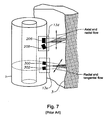
- FIG. 7 which is adapted from FIG. 3 of the '458 patent, another embodiment of the sensor configuration is shown.
- Sensor 13d is shown measuring axial flow and direction in the annulus.
- Sensor 13e includes a transmitting transducer 300 and a receiving transducer 302.
- Transducer 300 may be oriented on a circular plane on the circumference of the drill pipe 1 and is further angled such that it emits acoustic signals in a non-perpendicular direction into the annulus.
- Transducer 302 is oriented on the same circular plane on the circumference of drill pipe 1 and is angled so as to receive the acoustic signals transmitted by transducer 300, which have been Doppler shifted in frequency by the mud in the annulus.
- Processing logic (not shown) determines the radial velocity and direction of the mud in the annulus using the Doppler shifted signal and the baseline speed of sound measurement from sensor 13b.
- the velocity and flow measurement system utilizes pressure sensors to provide a signal indicative of the velocity of a fluid or of at least one of the fluids in a fluid mixture flowing in the pipe, as illustrated in FIG. 8 , which is adapted from FIG. 1 of the '584 patent. It will be understood that these methods and apparatus may be adapted to the annulus situation.
- the velocity and flow system will work over a wide range of mixtures of, for example, oil, water, and/or gas within the annulus.
- a system for detecting and measuring vortical pressure disturbances in a fluid moving in a pipe to determine the velocity and flow of the fluid includes a sensing section 110 along a pipe 112 and a velocity logic section 140.
- the pipe (or conduit) 112 has two measurement regions 114, 116 located a distance ⁇ X apart along the pipe 112.
- Each pair of pressure sensors 118, 120 and 122, 124 act as spatial filters to remove certain acoustic signals from the unsteady pressure signals, and the distances X 1 , X 2 are determined by the desired filtering characteristic for each spatial filter, as discussed below.
- the flow measurement system illustrated in FIG. 8 measures velocities associated with unsteady flow fields and/or pressure disturbances represented by 115.
- pressure disturbances could represent turbulent eddies (or vortical flow fields), inhomogeneities in the flow (such as bubbles, slugs, solids and the like), or any other properties of the flow having time varying or stochastic properties that are manifested at least in part in the form of unsteady pressures.
- Flow fields 115 are, in general, comprised of pressure disturbances having a wide variation in length scales and which have a variety of coherence length scales, such as those described in the reference " Sound and Sources of Sound," A. P. Dowling et al., Halsted Press, 1983 .
- flow fields 115 have temporal and spatial length scales as well as coherence length scales that differ from other disturbances in the flow.
- the methods of the present disclosure utilize these properties to preferentially select disturbances of a desired spatial (axial or transverse) length scale and coherence length scale, as more fully explained in the '584 patent.
- vortical flow field and vortical pressure field are used to describe the above-described group of unsteady pressure fields having temporal and spatial length and coherence scales described herein.
- the pressures P 1 , P 2 , P 3 , P 4 present at each of the sensors 118-124 may be measured through holes in the pipe 112 (which would be the drill pipe in accordance with the present disclosure) ported to sensors or by other techniques.
- the pressure sensors 118, 120, 122, 124 provide time-based pressure signals P 1 (t), P 2 (t), P 3 (t), P 4 (t) on lines 130, 132, 134, 136, respectively, to velocity logic 140, which provides a convection velocity signal V c (t) on a line 142.
- V c (t) is related to an average flow rate V f (t) of the fluid flowing in the pipe 112, or in the annulus in accordance with the present disclosure.
- velocity logic 140 may be implemented in software (using a microprocessor or computer) and/or firmware, or may be implemented using analog and/or digital hardware having sufficient memory, interfaces, and capacity to perform the functions described herein.
- the pressure signal P 1 (t) on line 130 is provided to a positive input of a summer 144 and the pressure signal P 2 (t) on line 132 is provided to a negative input of the summer 144.
- the inputs to summer 144 may be swapped with the pressure signal P 1 (t) on line 130 provided to the negative input and the pressure signal P 2 (t) on line 132 provided to the positive input without departing from the present disclosure.
- Line 145 is fed to bandpass filter 146, which passes a predetermined passband of frequencies and attenuates frequencies outside the passband.
- the passband of the filter 146 is set to filter out (or attenuate) the dc portion and the high frequency portion of the input signals and to pass the frequencies therebetween.
- passband filter 146 is set to pass frequencies from about 1 Hz to about 100 Hz, which is a useful range for detecting pressure disturbances in a 3-inch [7.6cm] inside-diameter pipe flowing water at 10 ft/sec [305cm/sec]. Other passbands may be used in other embodiments, if desired.
- Passband filter 146 provides a filtered signal P asf 1 on a line 148 to cross-correlation logic 150.
- the pressure signal P 3 (t) on line 134 is provided to a positive input of a summer 154 and the pressure signal P 4 (t) on line 136 is provided to a negative input of the summer 154.
- the pressure sensors 122,124 together with the summer 154 create a spatial filter 135.
- the line 155 is fed to a bandpass filter 156, similar to the bandpass filter 146 discussed above, which passes frequencies within the passband and attenuates frequencies outside the passband.
- the filter 156 provides a filtered signal P asf 2 on line 158 to cross-correlation logic 150.
- the signs on the summers 144,154 may be swapped if desired, provided the signs of both summers 144,154 are swapped together.
- the pressure signals P 1 , P 2 , P 3 , P 4 may be scaled prior to presentation to the summers 144,154.
- Signals P asf 1 and P asf 2 on lines 148,158, respectively are indicative of the presence of a pressure disturbance (such as vortices) in a flow field 115, which occur in sensing regions 114, 116, respectively.
- the cross-correlation logic 150 calculates a well-known time domain cross-correlation between the signals P asf 1 and P asf 2 on the lines 148,158, respectively, and provides an output signal on a line 160 indicative of the time delay ⁇ it takes for an vortical flow field 115 to propagate from one sensing region 114 to the other sensing region 116.
- Vortical flow disturbances are coherent dynamic conditions that can occur in the flow, and which substantially decay (by a predetermined amount) over a predetermined distance (or coherence length) and convect (or flow) at or near the average velocity of the fluid flow.
- a flow field 115 also has a stochastic or vortical pressure disturbance associated with it.
- the vortical flow disturbances 115 are distributed throughout the flow, particularly in high shear regions, such as boundary layers (e.g., along the inner wall of pipe 112) and are shown herein as discrete vortical flow fields 115. Because the vortical flow fields 115 (and the associated pressure disturbance) convect at or near the mean flow velocity, the propagation time delay ⁇ is related to the velocity of the flow, the distance ⁇ X between the measurement regions 114,116 being known.
- an optional circumferential groove 170 may be used in the inner diameter of pipe 112 to help generate vortices into the flow.
- groove 170 is not required for these methods to operate, which can operate using pressure disturbances occurring naturally in the flow of the fluid(s) within pipe 112.
- a plurality of axially spaced grooves may be used to generate further vortices.
- the dimensions and geometry of the groove(s) 170 may be set based on the expected flow conditions and other factors.
- the axial cross-sectional shape of groove 170 may be rectangular, square, triangular, circular, oval, star, or other shapes. Other techniques may be used as vortex generators if desired including those that may protrude within the inner diameter of pipe 112.
- a spacing signal ⁇ X on line 162, indicative of the distance ⁇ X between the sensing regions 114,116, is divided by the time delay signal ⁇ on the line 160 by a divider 164 which provides an output signal on the line 142 indicative of the convection velocity V c (t) of the fluid flowing in pipe 112, which is related to (or proportional to or approximately equal to) the average (or mean) flow velocity V f (t) of the fluid, as defined below: V c t ⁇ X / ⁇ ⁇ V f t
- the convection velocity V c (t) may then be calibrated to more precisely determine the mean velocity V f (t) if desired.
- the result of such calibration may require multiplying the value of the convection velocity V c (t) by a calibration constant (gain) and/or adding a calibration offset to obtain the mean flow velocity V f (t) with the desired accuracy.
- Other calibration may be used if desired. For some applications, such calibration may not be required to meet the desired accuracy.
- the velocities V f (t), V c (t) may be converted to volumetric flow rate by multiplying the velocity by the cross-sectional area of the pipe.
- filters can be used in combination with velocity logic 140 to determine flow rate properties of a fluid or a mixture of fluids.
- various spacing signals ⁇ X on a line 162 indicative of the distances ⁇ X 1 , ⁇ X 2 , ⁇ X 3 , ⁇ X 4 between the sensing regions are divided by the various time delay signals ⁇ associated with each time lag between the filters.
- Each divider 164 provides various output signals on the line 142 indicative of convection velocities V c (t) 1 , V c (t) 2 , V c (t) 3 , which, for example, each relate to a particular constituent of a three constituent mixture of fluids flowing in pipe 112.
- the various convection velocities are related to (or proportional to or approximately equal to) the average (or mean) flow velocity V f (t) 1 , V f (t) 2 , V f (t) 3 of the various constituents of the fluid mixture.
- the velocities V c (t) 1 , V c (t) 2 , V c (t) 3 and V f (t) 1 , V f (t) 2 , V f (t) 3 may be converted to volumetric flow rate if there is sufficient knowledge of the phase concentrations and cross sectional area of the pipe. Such configurations may also be used to determine a mean velocity for the fluid mixture.
- a primary interest lies in using one or more of the methods and apparatus described above to obtain a plurality of caliper or standoff distances in a plurality of segments, as well as a plurality of mud velocities in the segments, to calculate the total volumetric flow rate of mud in the annulus, and using this information to diagnose, make decisions on, and implement well treatment options to fix undesirable well behaviors such as lost circulation, fluid influxes, kicks, the build-up of cuttings beds, and the like, in the well.
- the skilled operator or designer will determine which methods and apparatus for measuring distances and velocities, and which well treatment options are best suited for a particular well and formation to achieve the highest efficiency without undue experimentation.
- root causes of for instance, lost circulation which may be encountered in a well and include an induced fracture, a natural fracture, vuggy formations, faults, poor isolation at a casing shoe, seepage losses, a hole in casing, etc.
- Each of these root causes may be best treated by some particular treatment, but no one treatment is most effective for all root causes. Therefore, understanding the root cause will lead to the selection of the most effective treatment.
- Placement of the treatment into the well can impact the effectiveness of the treatment. The distance the treatment must move through the well to reach the point to be treated can result in contamination of the treatment and, therefore, less effective results of the application of the treatment.
- Apparatus useful in the invention may include means for measuring temperature and annular fluid pressure in each segment.
- Suitable temperature measurement means include thermocouples, thermistors, resistant temperature detectors (RTDs), and the like.
- Suitable fluid pressure measurement means include piezoelectric sensors, fiber optic sensors, strain gauges, microelectromechanical (MEMS) sensors, and the like.
- the apparatus and methods of the present disclosure may also include means for calculating temperature- and pressure-corrected caliper or standoff distances using the measured temperature and annular fluid pressure in each segment.
- Suitable means for calculating include digital computers, and the like, either hard-wired or wirelessly connected to the tools, and which may include wired or wireless connections to human-readable devices, such as video CRT screens, printers, and the like.
- Useful drilling muds for use in the methods of the present disclosure include water-based, oil-based, and synthetic-based muds.
- the choice of formulation used is dictated in part by the nature of the formation in which drilling is to take place. For example, in various types of shale formations, the use of conventional water-based muds can result in a deterioration and collapse of the formation. The use of an oil-based formulation may circumvent this problem.
- a list of useful muds would include, but not be limited to, conventional muds, gas-cut muds (such as air-cut muds), balanced-activity oil muds, buffered muds, calcium muds, deflocculated muds, diesel-oil muds, emulsion muds (including oil emulsion muds), gyp muds, oil-invert emulsion oil muds, inhibitive muds, kill-weight muds, lime muds, low-colloid oil muds, low solids muds, magnetic muds, milk emulsion muds, native solids muds, PHPA (partially-hydrolyzed polyacrylamide) muds, potassium muds, red muds, saltwater (including seawater) muds, silicate muds, spud muds, thermally-activated muds, unweighted muds, weighted muds, water muds, and combinations
- Useful mud additives include, but are not limited to asphaltic mud additives, viscosity modifiers, emulsifying agents (for example, but not limited to, alkaline soaps of fatty acids), wetting agents (for example, but not limited to dodecylbenzene sulfonate), water (generally a NaCl or CaCl 2 brine), barite, barium sulfate, or other weighting agents, and normally amine treated clays (employed as a viscosification agent). More recently, neutralized sulfonated ionomers have been found to be particularly useful as viscosification agents in oil-based drilling muds. See, for example, U.S. Pat. Nos.
- These neutralized sulfonated ionomers are prepared by sulfonating an unsaturated polymer such as butyl rubber, EPDM terpolymer, partially hydrogenated polyisoprenes and polybutadienes. The sulfonated polymer is then neutralized with a base and thereafter steam stripped to remove the free carboxylic acid formed and to provide a neutralized sulfonated polymer crumb.
- an unsaturated polymer such as butyl rubber, EPDM terpolymer, partially hydrogenated polyisoprenes and polybutadienes.
- the sulfonated polymer is then neutralized with a base and thereafter steam stripped to remove the free carboxylic acid formed and to provide a neutralized sulfonated polymer crumb.
- the crumb must be milled, typically with a small amount of clay as a grinding aid, to get it in a form that is combinable with the oil and to keep it as a noncaking friable powder.
- the milled crumb is blended with lime to reduce the possibility of gelling when used in the oil.
- the ionomer containing powder is dissolved in the oil used in the drilling mud composition.
- viscosification agents selected from sulfonated and neutralized sulfonated ionomers can be readily incorporated into oil-based drilling muds in the form of an oil soluble concentrate containing the polymer as described in U.S. Pat. No. 5,906,966 .
- an additive concentrate for oil-based drilling muds comprises a drilling oil, especially a low toxicity oil, and from about 5 gm to about 20 gm of sulfonated or neutralized sulfonated polymer per 100 gm of oil. Oil solutions obtained from the sulfonated and neutralized sulfonated polymers used as viscosification agents are readily incorporated into drilling mud formulations.
- the mud system used may be an open or closed system. Any system used should allow for samples of circulating mud to be taken periodically, whether from a mud flow line, a mud return line, mud motor intake or discharge, mud house, mud pit, mud hopper, or two or more of these, as dictated by the resistivity data being received.
- the drilling rig operator (or owner of the well) has the opportunity to adjust the density, specific gravity, weight, viscosity, water content, oil content, composition, pH, flow rate, solids content, solids particle size distribution, resistivity, conductivity, and combinations of these properties of the mud.
- the mud report may be in paper format, or more likely today, electronic in format.
- the change in one or more of the list parameters and properties may be tracked, trended, and changed by a human operator (open-loop system) or by an automated system of sensors, controllers, analyzers, pumps, mixers, agitators (closed-loop systems).
- Drilling as used herein may include, but is not limited to, rotational drilling, directional drilling, non-directional (straight or linear) drilling, deviated drilling, geosteering, horizontal drilling, and the like.
- Rotational drilling may involve rotation of the entire drill string, or local rotation downhole using a drilling mud motor, where by pumping mud through the mud motor, the bit turns while the drillstring does not rotate or turns at a reduced rate, allowing the bit to drill in the direction it points.
- a turbodrill may be one tool used in the latter scenario.
- a turbodrill is a downhole assembly of bit and motor in which the bit alone is rotated by means of fluid turbine which is activated by the drilling mud. The mud turbine is usually placed just above the bit.
- Bit or “drill bit”, as used herein, includes, but is not limited to antiwhirl bits, bicenter bits, diamond bits, drag bits, fixed-cutter bits, polycrystalline diamond compact bits, roller-cone bits, and the like.
- the choice of bit like the choice of drilling mud, is dictated in part by the nature of the formation in which drilling is to take place.
- the rate of penetration (ROP) during drilling methods of this disclosure depends on permeability of the rock (the capacity of a porous rock formation to allow fluid to flow within the interconnecting pore network), the porosity of the rock (the volume of pore spaces between mineral grains expressed as a percentage of the total rock volume, and thus a measure of the capacity of the rock to hold oil, gas, or water), and the amount or percentage of vugs.
- the operator or owner of the well wishes the ROP to be as high as possible toward a known trap (any geological structure which precludes the migration of oil and gas through subsurface rocks, causing the hydrocarbons to accumulate into pools), without excess tripping in and out of the wellbore.
- Drill bit, drilling muds, and mud flow velocity and caliper measurement apparatus other than those specifically described above may be employed, and are considered within the disclosure.
Landscapes
- Geology (AREA)
- Life Sciences & Earth Sciences (AREA)
- Engineering & Computer Science (AREA)
- Physics & Mathematics (AREA)
- Mining & Mineral Resources (AREA)
- Geophysics (AREA)
- Environmental & Geological Engineering (AREA)
- Fluid Mechanics (AREA)
- General Life Sciences & Earth Sciences (AREA)
- Geochemistry & Mineralogy (AREA)
- Geophysics And Detection Of Objects (AREA)
- Measuring Volume Flow (AREA)
- Earth Drilling (AREA)
Claims (22)
- Procédé de détermination d'un débit volumétrique dans un espace annulaire à un ou plusieurs points dans un puits de forage, le procédé étant caractérisé en ce qu'il comprend :a) la mesure (2) d'une distance de pied à coulisse ou de centreur dans une pluralité de segments dans une coupe transversale d'un puits de forage sensiblement perpendiculaire à une tige de forage (1) au cours du forage ;b) la mesure d'une vitesse physique de matériau dans la pluralité de segments au cours du forage ;c) le calcul d'un débit volumétrique du matériau à travers chaque segment en utilisant les distances de pied à coulisse ou de centreur et les vitesses ; etd) la sommation ou l'intégration des débits volumétriques pour déterminer (14) un débit volumétrique total du matériau à un ou plusieurs points dans le puits.
- Procédé selon la revendication 1, comprenant la mesure (2) des distances de pied à coulisse ou de centreur dans la pluralité de segments en utilisant un procédé sélectionné parmi des procédés acoustiques, mécaniques, électromagnétiques et de densité rotationnelle.
- Procédé selon la revendication 2, dans lequel la distance de pied à coulisse ou de centreur est mesurée (2) en utilisant un procédé acoustique, le procédé acoustique étant sélectionné parmi un procédé d'écho d'impulsion acoustique, un procédé de décalage Doppler et un procédé de sonar.
- Procédé selon la revendication 3, comprenant en outre la mesure de la vitesse du son dans le matériau à l'intérieur ou sensiblement à proximité d'au moins un nombre substantiel de segments en utilisant une mesure de temps de parcours entre deux points séparés d'une distance connue, et en utilisant la mesure de la vitesse du son pour calculer avec plus de précision la distance à partir d'une mesure d'écho d'impulsion.
- Procédé selon la revendication 1, dans lequel la mesure (2) de la vitesse physique du matériau comprend l'utilisation d'un procédé sélectionné parmi une mesure de temps de parcours entre deux points séparés d'une distance connue, un procédé Doppler, un procédé de sonar, un procédé mécanique et un procédé d'activation de neutrons.
- Procédé selon la revendication 1, comprenant en outre la mesure d'une température et d'une pression de fluide annulaire dans chaque segment, et le calcul de distances de pied à coulisse ou de centreur à correction par température et pression en utilisant la température mesurée et la pression de fluide annulaire mesurée dans chaque segment.
- Procédé selon la revendication 6, dans lequel les distances de pied à coulisse ou de centreur à correction par température et pression sont appliquées pour corriger une partie ou l'intégralité des mesures de vitesse physique.
- Procédé selon la revendication 1, comprenant en outre l'utilisation du débit volumétrique total pour localiser un ou plusieurs points de dysfonctionnement de puits.
- Procédé selon la revendication 8, comprenant en outre l'utilisation des informations relatives à l'emplacement d'un ou plusieurs points de dysfonctionnement de puits pour diagnostiquer la cause de base du dysfonctionnement de puits, et, une fois que la cause de base est diagnostiquée, la sélection d'un traitement de puits approprié, et le placement du traitement de puits à l'endroit du dysfonctionnement dans le puits.
- Procédé selon la revendication 1, comprenant en outre la mesure des distances et des vitesses en continu.
- Procédé selon la revendication 1, dans lequel les mesures de vitesse de pied à coulisse et physique du matériau sont prises à un point unique le long de la tige de forage (1).
- Procédé selon la revendication 1, dans lequel les mesures de vitesse de pied à coulisse et physique du matériau sont prises à une pluralité de points le long de la tige de forage (1).
- Procédé de localisation d'un ou plusieurs points de dysfonctionnement dans un espace annulaire d'un puits pendant le forage du puits avec une tige de forage (1), un trépan attaché à la tige de forage (1) et une boue de forage en écoulement, le procédé étant caractérisé en ce qu'il comprend :a) la mesure (2) d'une distance de pied à coulisse ou de centreur dans une pluralité de segments dans une coupe transversale du puits de forage sensiblement perpendiculaire à la tige de forage (1) ;b) la mesure d'une vitesse physique de matériau dans la pluralité de segments ;c) le calcul d'un débit volumétrique du matériau à travers chaque segment en utilisant les distances de pied à coulisse ou de centreur et les vitesses ;d) la sommation ou l'intégration des débits volumétriques pour déterminer (14) un débit volumétrique total du matériau à un ou plusieurs points dans le puits ; ete) l'utilisation du débit volumétrique total pour localiser un ou plusieurs points de dysfonctionnement dans le puits.
- Procédé selon la revendication 13, comprenant la mesure des distances de pied à coulisse ou de centreur dans la pluralité de segments en utilisant un procédé sélectionné parmi des procédés acoustiques, mécaniques, électromagnétiques et de densité rotationnelle.
- Procédé selon la revendication 14, dans lequel la distance de pied à coulisse ou de centreur est mesurée en utilisant un procédé acoustique, le procédé acoustique étant sélectionné parmi un procédé d'écho d'impulsion acoustique, un procédé de décalage Doppler et un procédé de sonar.
- Procédé selon la revendication 13, comprenant en outre l'utilisation des informations relatives au point ou aux points de dysfonctionnement de puits pour diagnostiquer (24) la cause de base du dysfonctionnement de puits.
- Procédé selon la revendication 16, comprenant en outre, une fois que la cause de base du dysfonctionnement de puits est diagnostiquée, la sélection (28) d'un traitement de puits approprié, et le placement du traitement de puits à l'endroit du dysfonctionnement dans le puits.
- Appareil de détermination d'un débit volumétrique à un ou plusieurs points au fond d'un trou dans un espace annulaire de puits de forage, l'appareil étant caractérisé en ce qu'il comprend :a) un ou plusieurs capteurs pour mesurer une pluralité de distances entre une tige de forage et une paroi de trou de forage dans une pluralité de segments annulaires ;b) un capteur pour mesurer une pluralité de vitesses physiques de matériau dans la pluralité de segments annulaires ;c) un dispositif de calcul pour calculer une pluralité de débits volumétriques de matériau en utilisant la pluralité de distances et la pluralité de vitesses physiques ; etd) un dispositif de sommation ou d'intégration pour sommer la pluralité de débits volumétriques pour créer un débit volumétrique total du matériau à un ou plusieurs points dans l'espace annulaire.
- Appareil selon la revendication 18, dans lequel l'un ou plusieurs capteurs pour mesurer une pluralité de distances se trouvent dans un plan sensiblement perpendiculaire à la tige de forage (1).
- Appareil selon la revendication 18, dans lequel l'un ou plusieurs capteurs pour mesurer une pluralité de distances entre une tige de forage (1) et une paroi de trou de forage (3) sont des capteurs acoustiques (9, 11).
- Appareil selon la revendication 18, comprenant en outre un moyen pour mesurer une vitesse physique du matériau à l'intérieur ou sensiblement à proximité d'au moins un nombre substantiel de segments.
- Appareil selon la revendication 18, comprenant en outre un moyen pour mesurer une température et une pression de fluide annulaire dans chaque segment, et un moyen pour calculer des distances de pied à coulisse ou de centreur à correction par température et pression en utilisant la température mesurée et la pression de fluide annulaire mesurée dans chaque segment.
Priority Applications (1)
| Application Number | Priority Date | Filing Date | Title |
|---|---|---|---|
| CY20141100651T CY1115385T1 (el) | 2009-04-10 | 2014-08-13 | Μετρηση του ρυθμου ροης λασπης στο δακτυλιο κατα τη διατρηση γεωτρησης και χρηση αυτου για τον εντοπισμο δυσλειτουργιων της γεωτρησης |
Applications Claiming Priority (2)
| Application Number | Priority Date | Filing Date | Title |
|---|---|---|---|
| US12/421,849 US7950451B2 (en) | 2009-04-10 | 2009-04-10 | Annulus mud flow rate measurement while drilling and use thereof to detect well dysfunction |
| PCT/US2010/027084 WO2010117549A1 (fr) | 2009-04-10 | 2010-03-12 | Mesure de débit de boues d'espace annulaire lors du forage et utilisation de cette mesure pour détecter des dysfonctionnements de puits |
Publications (2)
| Publication Number | Publication Date |
|---|---|
| EP2417331A1 EP2417331A1 (fr) | 2012-02-15 |
| EP2417331B1 true EP2417331B1 (fr) | 2014-05-14 |
Family
ID=42671719
Family Applications (1)
| Application Number | Title | Priority Date | Filing Date |
|---|---|---|---|
| EP10713278.9A Not-in-force EP2417331B1 (fr) | 2009-04-10 | 2010-03-12 | Mesure du débit de la boue de forage dans un espace annulaire pour détecter des disfonctionnements dans le trou de forage |
Country Status (9)
| Country | Link |
|---|---|
| US (1) | US7950451B2 (fr) |
| EP (1) | EP2417331B1 (fr) |
| AU (1) | AU2010235062B2 (fr) |
| BR (1) | BRPI1014696A2 (fr) |
| CA (1) | CA2756506C (fr) |
| CY (1) | CY1115385T1 (fr) |
| DK (1) | DK2417331T3 (fr) |
| EA (1) | EA201101271A1 (fr) |
| WO (1) | WO2010117549A1 (fr) |
Cited By (2)
| Publication number | Priority date | Publication date | Assignee | Title |
|---|---|---|---|---|
| US10760401B2 (en) | 2017-09-29 | 2020-09-01 | Baker Hughes, A Ge Company, Llc | Downhole system for determining a rate of penetration of a downhole tool and related methods |
| US12535001B2 (en) | 2017-09-29 | 2026-01-27 | Baker Hughes Oilfield Operations Llc | Downhole acoustic system for determining a rate of penetration of a drill string and related methods |
Families Citing this family (34)
| Publication number | Priority date | Publication date | Assignee | Title |
|---|---|---|---|---|
| GB2460096B (en) | 2008-06-27 | 2010-04-07 | Wajid Rasheed | Expansion and calliper tool |
| US8669516B2 (en) | 2010-08-20 | 2014-03-11 | Baker Hughes Incorporated | Using LWT service to identify loss circulation areas in a wellbore |
| NO334117B1 (no) | 2010-10-29 | 2013-12-16 | Resman As | En fremgangsmåte for estimering av et innstrømningsprofil for i det minste en av brønnfluidene olje, gass eller vann til en produserende petroleumsbrønn |
| ES2657295T3 (es) | 2012-01-20 | 2018-03-02 | Strada Design Limited | Sistema de perforación de circulación doble |
| US20130195695A1 (en) * | 2012-01-30 | 2013-08-01 | General Electric Company | Hollow rotor motor and systems comprising the same |
| US9418647B2 (en) | 2012-06-07 | 2016-08-16 | California Institute Of Technology | Communication in pipes using acoustic modems that provide minimal obstruction to fluid flow |
| US20140180658A1 (en) * | 2012-09-04 | 2014-06-26 | Schlumberger Technology Corporation | Model-driven surveillance and diagnostics |
| CN103148992B (zh) * | 2013-03-11 | 2015-07-08 | 南京帝坝工程科技有限公司 | 三维流速矢量能量与质量测量仪 |
| US8935957B2 (en) * | 2013-03-13 | 2015-01-20 | Halliburton Energy Services, Inc. | Methods of designing a drilling fluid having suspendable loss circulation material |
| US9410422B2 (en) | 2013-09-13 | 2016-08-09 | Chevron U.S.A. Inc. | Alternative gauging system for production well testing and related methods |
| WO2015048670A2 (fr) | 2013-09-27 | 2015-04-02 | National Oilwell Varco, L.P. | Détection de température en fond de forage du flux de fluide dans et autour d'un train de tiges |
| US9217808B2 (en) * | 2013-11-07 | 2015-12-22 | Schlumberger Technology Corporation | Wellbore signal monitor with tangential seismic sensors for tube-wave noise reduction |
| US9982519B2 (en) | 2014-07-14 | 2018-05-29 | Saudi Arabian Oil Company | Flow meter well tool |
| MX2017002734A (es) * | 2014-09-10 | 2017-10-20 | Halliburton Energy Services Inc | Flujo de trabajo de multiples sensores para la evaluacion del flujo de agua en multiples sartas de revestimiento. |
| US9835022B2 (en) | 2014-09-10 | 2017-12-05 | Halliburton Energy Services, Inc. | Multi-sensor workflow for evaluation of water flow in multiple casing strings with distributed sensors data |
| CN105737916B (zh) | 2014-12-08 | 2019-06-18 | 通用电气公司 | 超声流体测量系统及方法 |
| CA2909167C (fr) | 2014-12-30 | 2016-09-13 | Halliburton Energy Services, Inc. | Materiaux de circulation a perte de mems servant a evaluer la perte de fluide et renforcement de puits de forage pendant une operation de forage |
| GB2552098B (en) | 2015-02-27 | 2020-12-23 | Halliburton Energy Services Inc | Determining drilling fluid loss in a wellbore |
| WO2016145524A1 (fr) | 2015-03-16 | 2016-09-22 | Darkvision Technologies Inc. | Dispositif et procédé pour imager un écoulement dans des puits de pétrole et de gaz à l'aide d'ultrasons doppler de réseau à commande de phase |
| GB2554214A (en) * | 2015-05-22 | 2018-03-28 | Halliburton Energy Services Inc | In-situ borehole fluid speed and attenuation measurement in an ultrasonic scanning tool |
| AU2016396055B2 (en) * | 2016-03-03 | 2022-12-08 | Halliburton Energy Services, Inc. | Casing thickness estimation by frequency correlation |
| US11242744B1 (en) | 2016-05-06 | 2022-02-08 | WellWorc, Inc. | Real time flow analysis methods and continuous mass balance and wellbore pressure calculations from real-time density and flow measurements |
| US10738551B1 (en) * | 2016-05-06 | 2020-08-11 | WellWorc, Inc | Real time flow analysis methods and continuous mass balance and wellbore pressure calculations from real-time density and flow measurements |
| BR112019003245A2 (pt) * | 2016-09-27 | 2019-06-18 | Halliburton Energy Services Inc | transdutor ultrassônico multidirecional de fundo de poço e sistema ultrassônico multidirecional de fundo de poço |
| US10557340B2 (en) * | 2017-10-23 | 2020-02-11 | Aver Technologies, Inc. | Ultrasonic borescope for drilled shaft inspection |
| US11378506B2 (en) | 2017-12-12 | 2022-07-05 | Baker Hughes, A Ge Company, Llc | Methods and systems for monitoring drilling fluid rheological characteristics |
| NL2021236B1 (en) * | 2018-07-04 | 2020-01-15 | Rbp Tech Holding B V | Methods and systems for characterising a fluid flowing in a conduit |
| CN109339768B (zh) * | 2018-10-23 | 2022-04-22 | 西南石油大学 | 一种钻井微溢流随钻监测方法 |
| US11726224B2 (en) * | 2019-01-24 | 2023-08-15 | Baker Hughes, A Ge Company, Llc | B annulus acoustic pressure sensing |
| US11371301B2 (en) * | 2019-02-05 | 2022-06-28 | Saudi Arabian Oil Company | Lost circulation shape deployment |
| US11359488B2 (en) * | 2019-03-12 | 2022-06-14 | Baker Hughes Oilfield Operations Llc | Self-calibrated method of determining borehole fluid acoustic properties |
| WO2020236220A1 (fr) * | 2019-05-20 | 2020-11-26 | Halliburton Energy Services, Inc. | Systèmes et procédés de capteurs acoustiques |
| CN111058835B (zh) * | 2019-12-05 | 2022-11-29 | 中国海洋石油集团有限公司 | 一种双向通信短节 |
| US20240084695A1 (en) * | 2022-09-09 | 2024-03-14 | Saudi Arabian Oil Company | Casing deformation monitoring |
Family Cites Families (47)
| Publication number | Priority date | Publication date | Assignee | Title |
|---|---|---|---|---|
| US3835953A (en) * | 1973-01-26 | 1974-09-17 | Simplec Mfg Co Inc | Acoustic caliper logging |
| US4447338A (en) * | 1981-08-12 | 1984-05-08 | Exxon Research And Engineering Co. | Drilling mud viscosification agents based on sulfonated ionomers |
| FR2518638A1 (fr) * | 1981-12-22 | 1983-06-24 | Schlumberger Prospection | Procede et dispositif acoustiques pour la mesure de dimensions transversales d'un trou, notamment dans un puits |
| US4442011A (en) * | 1981-12-21 | 1984-04-10 | Exxon Research And Engineering Co. | Drilling mud viscosification agents based on sulfonated ionomers |
| US4527425A (en) * | 1982-12-10 | 1985-07-09 | Nl Industries, Inc. | System for detecting blow out and lost circulation in a borehole |
| US4532812A (en) * | 1983-06-30 | 1985-08-06 | Nl Industries, Inc. | Parametric acoustic flow meter |
| US4665511A (en) * | 1984-03-30 | 1987-05-12 | Nl Industries, Inc. | System for acoustic caliper measurements |
| US4964085A (en) | 1986-02-25 | 1990-10-16 | Baroid Technology, Inc. | Non-contact borehole caliber measurement |
| US4899112A (en) * | 1987-10-30 | 1990-02-06 | Schlumberger Technology Corporation | Well logging apparatus and method for determining formation resistivity at a shallow and a deep depth |
| US4979112A (en) * | 1988-05-11 | 1990-12-18 | Baker Hughes Incorporated | Method and apparatus for acoustic measurement of mud flow downhole |
| US4905203A (en) * | 1988-09-30 | 1990-02-27 | Texaco Inc. | Downhole doppler flowmeter |
| US4947683A (en) * | 1989-08-03 | 1990-08-14 | Halliburton Logging Services, Inc. | Pulsed ultrasonic doppler borehole fluid measuring apparatus |
| CA2009977A1 (fr) | 1990-02-14 | 1991-08-14 | Jackie C. Sims | Debitmetre immerge doppler |
| US5130950A (en) * | 1990-05-16 | 1992-07-14 | Schlumberger Technology Corporation | Ultrasonic measurement apparatus |
| US5091644A (en) * | 1991-01-15 | 1992-02-25 | Teleco Oilfield Services Inc. | Method for analyzing formation data from a formation evaluation MWD logging tool |
| US5906966A (en) * | 1991-06-24 | 1999-05-25 | Exxon Research And Engineering Co. | Drilling mud additives and in adding viscosification additives to oil-based drilling muds |
| US5341345A (en) * | 1993-08-09 | 1994-08-23 | Baker Hughes Incorporated | Ultrasonic stand-off gauge |
| CA2133286C (fr) * | 1993-09-30 | 2005-08-09 | Gordon Moake | Appareil et dispositif pour le mesurage des parametres d'un forage |
| US5430259A (en) * | 1993-12-10 | 1995-07-04 | Baker Hughes Incorporated | Measurement of stand-off distance and drilling fluid sound speed while drilling |
| US5387767A (en) * | 1993-12-23 | 1995-02-07 | Schlumberger Technology Corporation | Transmitter for sonic logging-while-drilling |
| US5519668A (en) * | 1994-05-26 | 1996-05-21 | Schlumberger Technology Corporation | Methods and devices for real-time formation imaging through measurement while drilling telemetry |
| US5900733A (en) * | 1996-02-07 | 1999-05-04 | Schlumberger Technology Corporation | Well logging method and apparatus for determining downhole Borehole fluid resistivity, borehole diameter, and borehole corrected formation resistivity |
| US5638337A (en) * | 1996-08-01 | 1997-06-10 | Western Atlas International, Inc. | Method for computing borehole geometry from ultrasonic pulse echo data |
| US5737277A (en) * | 1996-08-01 | 1998-04-07 | Western Atlas International, Inc. | Method for computing borehole geometry from ultrasonic pulse echo data |
| US5987385A (en) * | 1997-08-29 | 1999-11-16 | Dresser Industries, Inc. | Method and apparatus for creating an image of an earth borehole or a well casing |
| US6285026B1 (en) * | 1999-03-30 | 2001-09-04 | Schlumberger Technology Corporation | Borehole caliper derived from neutron porosity measurements |
| US6691584B2 (en) * | 1999-07-02 | 2004-02-17 | Weatherford/Lamb, Inc. | Flow rate measurement using unsteady pressures |
| AU3334800A (en) * | 2000-03-09 | 2001-09-17 | Vladimir Drobkov | Simultaneous determination of multiphase flowrates and concentrations |
| US6672163B2 (en) * | 2000-03-14 | 2004-01-06 | Halliburton Energy Services, Inc. | Acoustic sensor for fluid characterization |
| US6378357B1 (en) * | 2000-03-14 | 2002-04-30 | Halliburton Energy Services, Inc. | Method of fluid rheology characterization and apparatus therefor |
| US6513385B1 (en) * | 2001-05-08 | 2003-02-04 | Halliburton Energy Services, Inc. | Acoustic sensor for pipeline deposition characterization and monitoring |
| US6618322B1 (en) * | 2001-08-08 | 2003-09-09 | Baker Hughes Incorporated | Method and apparatus for measuring acoustic mud velocity and acoustic caliper |
| US6725162B2 (en) * | 2001-12-13 | 2004-04-20 | Schlumberger Technology Corporation | Method for determining wellbore diameter by processing multiple sensor measurements |
| CA2485974A1 (fr) * | 2002-05-15 | 2003-11-27 | Halliburton Energy Services, Inc. | Mesure du debit d'un fluide en fond de puits par doppler acoustique |
| US6891777B2 (en) * | 2002-06-19 | 2005-05-10 | Schlumberger Technology Corporation | Subsurface borehole evaluation and downhole tool position determination methods |
| US20040095847A1 (en) * | 2002-11-18 | 2004-05-20 | Baker Hughes Incorporated | Acoustic devices to measure ultrasound velocity in drilling mud |
| ATE319914T1 (de) * | 2002-12-31 | 2006-03-15 | Schlumberger Services Petrol | Vorrichtung und verfahren zur messung von ultraschallgeschwindigkeit in bohrflüssigkeiten |
| DE60219185D1 (de) * | 2002-12-31 | 2007-05-10 | Schlumberger Services Petrol | Messung der Strömungsgeschwindigkeit von Spülung mittels gepulster Neutronen |
| GB2399111B (en) | 2003-03-07 | 2005-10-05 | Schlumberger Holdings | Methods for detecting while drilling underbalanced the presence and depth of water produced from the formation and for measuring parameters related thereto |
| US7007752B2 (en) * | 2003-03-21 | 2006-03-07 | Halliburton Energy Services, Inc. | Well treatment fluid and methods with oxidized polysaccharide-based polymers |
| US7128148B2 (en) * | 2004-04-16 | 2006-10-31 | Halliburton Energy Services, Inc. | Well treatment fluid and methods for blocking permeability of a subterranean zone |
| US20050259512A1 (en) * | 2004-05-24 | 2005-11-24 | Halliburton Energy Services, Inc. | Acoustic caliper with transducer array for improved off-center performance |
| US7260477B2 (en) * | 2004-06-18 | 2007-08-21 | Pathfinder Energy Services, Inc. | Estimation of borehole geometry parameters and lateral tool displacements |
| EP1969204A4 (fr) * | 2006-01-05 | 2012-12-26 | Prad Res & Dev Ltd | Procédé de détermination d'entrées du fluide de formation dans un puits ou des pertes de fluide de forage s'en échappant au moyen d'un système de mesure de la pression dynamique dans un espace annulaire |
| US7596452B2 (en) * | 2007-06-28 | 2009-09-29 | Baker Hughes Incorporated | Compensated caliper using combined acoustic and density measurements |
| US8130591B2 (en) | 2007-08-29 | 2012-03-06 | Baker Hughes Incorporated | Downhole measurements of mud acoustic velocity |
| US20090195408A1 (en) | 2007-08-29 | 2009-08-06 | Baker Hughes Incorporated | Methods and apparatus for high-speed telemetry while drilling |
-
2009
- 2009-04-10 US US12/421,849 patent/US7950451B2/en not_active Expired - Fee Related
-
2010
- 2010-03-12 EA EA201101271A patent/EA201101271A1/ru unknown
- 2010-03-12 CA CA2756506A patent/CA2756506C/fr not_active Expired - Fee Related
- 2010-03-12 EP EP10713278.9A patent/EP2417331B1/fr not_active Not-in-force
- 2010-03-12 DK DK10713278.9T patent/DK2417331T3/da active
- 2010-03-12 BR BRPI1014696A patent/BRPI1014696A2/pt not_active IP Right Cessation
- 2010-03-12 AU AU2010235062A patent/AU2010235062B2/en not_active Expired - Fee Related
- 2010-03-12 WO PCT/US2010/027084 patent/WO2010117549A1/fr not_active Ceased
-
2014
- 2014-08-13 CY CY20141100651T patent/CY1115385T1/el unknown
Cited By (2)
| Publication number | Priority date | Publication date | Assignee | Title |
|---|---|---|---|---|
| US10760401B2 (en) | 2017-09-29 | 2020-09-01 | Baker Hughes, A Ge Company, Llc | Downhole system for determining a rate of penetration of a downhole tool and related methods |
| US12535001B2 (en) | 2017-09-29 | 2026-01-27 | Baker Hughes Oilfield Operations Llc | Downhole acoustic system for determining a rate of penetration of a drill string and related methods |
Also Published As
| Publication number | Publication date |
|---|---|
| AU2010235062B2 (en) | 2015-02-26 |
| CA2756506A1 (fr) | 2010-10-14 |
| CA2756506C (fr) | 2014-08-26 |
| US20100258303A1 (en) | 2010-10-14 |
| EA201101271A1 (ru) | 2012-05-30 |
| EP2417331A1 (fr) | 2012-02-15 |
| AU2010235062A1 (en) | 2011-11-24 |
| CY1115385T1 (el) | 2017-01-04 |
| US7950451B2 (en) | 2011-05-31 |
| BRPI1014696A2 (pt) | 2016-04-12 |
| DK2417331T3 (da) | 2014-07-28 |
| WO2010117549A1 (fr) | 2010-10-14 |
Similar Documents
| Publication | Publication Date | Title |
|---|---|---|
| EP2417331B1 (fr) | Mesure du débit de la boue de forage dans un espace annulaire pour détecter des disfonctionnements dans le trou de forage | |
| US11378506B2 (en) | Methods and systems for monitoring drilling fluid rheological characteristics | |
| US6829947B2 (en) | Acoustic Doppler downhole fluid flow measurement | |
| US4733233A (en) | Method and apparatus for borehole fluid influx detection | |
| AU2011369452B2 (en) | Azimuthal brittleness logging systems and methods | |
| US4733232A (en) | Method and apparatus for borehole fluid influx detection | |
| EP3063367B1 (fr) | Analyse in situ de déblais de fond de trou | |
| US20150176402A1 (en) | Applications Based On Fluid Properties Measured Downhole | |
| US20080047337A1 (en) | Early Kick Detection in an Oil and Gas Well | |
| US20190277806A1 (en) | Downhole tool for measuring fluid flow | |
| US20140260589A1 (en) | Downhole tool for determining flow velocity | |
| MX2012009933A (es) | Metodos para evaluar los cambios de volumen en el agujero durante la perforacion. | |
| US11966002B2 (en) | Systems and methods for downhole determination of drilling characteristics | |
| US10041343B2 (en) | Micro-sonic density imaging while drilling systems and methods | |
| WO2013126388A1 (fr) | Détection précoce d'à-coup de pression dans un puits de pétrole et de gaz | |
| Stokka et al. | Gas kick warner-an early gas influx detection method | |
| CA1218740A (fr) | Methode et dispositif de detection de l'afflux de fluide dans un forage | |
| US8077545B2 (en) | Method for detecting gas influx in wellbores and its application to identifying gas bearing formations | |
| Bryant et al. | Field results of an MWD acoustic gas influx detection technique | |
| NO20230613A1 (en) | Methodology for annular solids and fluids differentiation through integration of shear and flexural ultrasonic acoustic waves | |
| Link et al. | Fracture Prediction, Actual 2010 Drilling Results, and Full Wave Forward Modeling: An Integrated Technologies Approach |
Legal Events
| Date | Code | Title | Description |
|---|---|---|---|
| PUAI | Public reference made under article 153(3) epc to a published international application that has entered the european phase |
Free format text: ORIGINAL CODE: 0009012 |
|
| 17P | Request for examination filed |
Effective date: 20111104 |
|
| AK | Designated contracting states |
Kind code of ref document: A1 Designated state(s): AT BE BG CH CY CZ DE DK EE ES FI FR GB GR HR HU IE IS IT LI LT LU LV MC MK MT NL NO PL PT RO SE SI SK SM TR |
|
| DAX | Request for extension of the european patent (deleted) | ||
| GRAP | Despatch of communication of intention to grant a patent |
Free format text: ORIGINAL CODE: EPIDOSNIGR1 |
|
| RAP1 | Party data changed (applicant data changed or rights of an application transferred) |
Owner name: BP CORPORATION NORTH AMERICA INC. |
|
| RIN1 | Information on inventor provided before grant (corrected) |
Inventor name: ALBERTY, MARK, W. |
|
| GRAP | Despatch of communication of intention to grant a patent |
Free format text: ORIGINAL CODE: EPIDOSNIGR1 |
|
| INTG | Intention to grant announced |
Effective date: 20131119 |
|
| GRAS | Grant fee paid |
Free format text: ORIGINAL CODE: EPIDOSNIGR3 |
|
| GRAA | (expected) grant |
Free format text: ORIGINAL CODE: 0009210 |
|
| AK | Designated contracting states |
Kind code of ref document: B1 Designated state(s): AT BE BG CH CY CZ DE DK EE ES FI FR GB GR HR HU IE IS IT LI LT LU LV MC MK MT NL NO PL PT RO SE SI SK SM TR |
|
| REG | Reference to a national code |
Ref country code: GB Ref legal event code: FG4D |
|
| REG | Reference to a national code |
Ref country code: AT Ref legal event code: REF Ref document number: 668455 Country of ref document: AT Kind code of ref document: T Effective date: 20140615 |
|
| REG | Reference to a national code |
Ref country code: IE Ref legal event code: FG4D |
|
| REG | Reference to a national code |
Ref country code: DE Ref legal event code: R096 Ref document number: 602010016073 Country of ref document: DE Effective date: 20140703 |
|
| REG | Reference to a national code |
Ref country code: DK Ref legal event code: T3 Effective date: 20140725 |
|
| REG | Reference to a national code |
Ref country code: NL Ref legal event code: T3 |
|
| REG | Reference to a national code |
Ref country code: RO Ref legal event code: EPE |
|
| REG | Reference to a national code |
Ref country code: EE Ref legal event code: FG4A Ref document number: E009368 Country of ref document: EE Effective date: 20140619 |
|
| REG | Reference to a national code |
Ref country code: NO Ref legal event code: T2 Effective date: 20140514 |
|
| REG | Reference to a national code |
Ref country code: GR Ref legal event code: EP Ref document number: 20140401541 Country of ref document: GR Effective date: 20140930 |
|
| REG | Reference to a national code |
Ref country code: LT Ref legal event code: MG4D |
|
| PG25 | Lapsed in a contracting state [announced via postgrant information from national office to epo] |
Ref country code: LT Free format text: LAPSE BECAUSE OF FAILURE TO SUBMIT A TRANSLATION OF THE DESCRIPTION OR TO PAY THE FEE WITHIN THE PRESCRIBED TIME-LIMIT Effective date: 20140514 Ref country code: IS Free format text: LAPSE BECAUSE OF FAILURE TO SUBMIT A TRANSLATION OF THE DESCRIPTION OR TO PAY THE FEE WITHIN THE PRESCRIBED TIME-LIMIT Effective date: 20140914 |
|
| PG25 | Lapsed in a contracting state [announced via postgrant information from national office to epo] |
Ref country code: HR Free format text: LAPSE BECAUSE OF FAILURE TO SUBMIT A TRANSLATION OF THE DESCRIPTION OR TO PAY THE FEE WITHIN THE PRESCRIBED TIME-LIMIT Effective date: 20140514 Ref country code: ES Free format text: LAPSE BECAUSE OF FAILURE TO SUBMIT A TRANSLATION OF THE DESCRIPTION OR TO PAY THE FEE WITHIN THE PRESCRIBED TIME-LIMIT Effective date: 20140514 Ref country code: SE Free format text: LAPSE BECAUSE OF FAILURE TO SUBMIT A TRANSLATION OF THE DESCRIPTION OR TO PAY THE FEE WITHIN THE PRESCRIBED TIME-LIMIT Effective date: 20140514 Ref country code: LV Free format text: LAPSE BECAUSE OF FAILURE TO SUBMIT A TRANSLATION OF THE DESCRIPTION OR TO PAY THE FEE WITHIN THE PRESCRIBED TIME-LIMIT Effective date: 20140514 Ref country code: PL Free format text: LAPSE BECAUSE OF FAILURE TO SUBMIT A TRANSLATION OF THE DESCRIPTION OR TO PAY THE FEE WITHIN THE PRESCRIBED TIME-LIMIT Effective date: 20140514 |
|
| PG25 | Lapsed in a contracting state [announced via postgrant information from national office to epo] |
Ref country code: PT Free format text: LAPSE BECAUSE OF FAILURE TO SUBMIT A TRANSLATION OF THE DESCRIPTION OR TO PAY THE FEE WITHIN THE PRESCRIBED TIME-LIMIT Effective date: 20140915 |
|
| PG25 | Lapsed in a contracting state [announced via postgrant information from national office to epo] |
Ref country code: CZ Free format text: LAPSE BECAUSE OF FAILURE TO SUBMIT A TRANSLATION OF THE DESCRIPTION OR TO PAY THE FEE WITHIN THE PRESCRIBED TIME-LIMIT Effective date: 20140514 Ref country code: BE Free format text: LAPSE BECAUSE OF FAILURE TO SUBMIT A TRANSLATION OF THE DESCRIPTION OR TO PAY THE FEE WITHIN THE PRESCRIBED TIME-LIMIT Effective date: 20140514 Ref country code: SK Free format text: LAPSE BECAUSE OF FAILURE TO SUBMIT A TRANSLATION OF THE DESCRIPTION OR TO PAY THE FEE WITHIN THE PRESCRIBED TIME-LIMIT Effective date: 20140514 |
|
| REG | Reference to a national code |
Ref country code: DE Ref legal event code: R097 Ref document number: 602010016073 Country of ref document: DE |
|
| REG | Reference to a national code |
Ref country code: FR Ref legal event code: PLFP Year of fee payment: 6 |
|
| PLBE | No opposition filed within time limit |
Free format text: ORIGINAL CODE: 0009261 |
|
| STAA | Information on the status of an ep patent application or granted ep patent |
Free format text: STATUS: NO OPPOSITION FILED WITHIN TIME LIMIT |
|
| 26N | No opposition filed |
Effective date: 20150217 |
|
| PGFP | Annual fee paid to national office [announced via postgrant information from national office to epo] |
Ref country code: BG Payment date: 20150325 Year of fee payment: 6 Ref country code: FI Payment date: 20150327 Year of fee payment: 6 Ref country code: EE Payment date: 20150223 Year of fee payment: 6 Ref country code: IE Payment date: 20150327 Year of fee payment: 6 Ref country code: RO Payment date: 20150227 Year of fee payment: 6 Ref country code: DE Payment date: 20150327 Year of fee payment: 6 Ref country code: NL Payment date: 20150326 Year of fee payment: 6 Ref country code: DK Payment date: 20150325 Year of fee payment: 6 Ref country code: IT Payment date: 20150323 Year of fee payment: 6 |
|
| REG | Reference to a national code |
Ref country code: DE Ref legal event code: R097 Ref document number: 602010016073 Country of ref document: DE Effective date: 20150217 |
|
| PGFP | Annual fee paid to national office [announced via postgrant information from national office to epo] |
Ref country code: FR Payment date: 20150317 Year of fee payment: 6 Ref country code: AT Payment date: 20150219 Year of fee payment: 6 Ref country code: GR Payment date: 20150330 Year of fee payment: 6 Ref country code: TR Payment date: 20150303 Year of fee payment: 6 Ref country code: GB Payment date: 20150327 Year of fee payment: 6 |
|
| PG25 | Lapsed in a contracting state [announced via postgrant information from national office to epo] |
Ref country code: SI Free format text: LAPSE BECAUSE OF FAILURE TO SUBMIT A TRANSLATION OF THE DESCRIPTION OR TO PAY THE FEE WITHIN THE PRESCRIBED TIME-LIMIT Effective date: 20140514 |
|
| PGFP | Annual fee paid to national office [announced via postgrant information from national office to epo] |
Ref country code: CY Payment date: 20150220 Year of fee payment: 6 Ref country code: NO Payment date: 20150327 Year of fee payment: 6 |
|
| PG25 | Lapsed in a contracting state [announced via postgrant information from national office to epo] |
Ref country code: MC Free format text: LAPSE BECAUSE OF FAILURE TO SUBMIT A TRANSLATION OF THE DESCRIPTION OR TO PAY THE FEE WITHIN THE PRESCRIBED TIME-LIMIT Effective date: 20140514 Ref country code: LU Free format text: LAPSE BECAUSE OF FAILURE TO SUBMIT A TRANSLATION OF THE DESCRIPTION OR TO PAY THE FEE WITHIN THE PRESCRIBED TIME-LIMIT Effective date: 20150312 |
|
| REG | Reference to a national code |
Ref country code: CH Ref legal event code: PL |
|
| PG25 | Lapsed in a contracting state [announced via postgrant information from national office to epo] |
Ref country code: CH Free format text: LAPSE BECAUSE OF NON-PAYMENT OF DUE FEES Effective date: 20150331 Ref country code: LI Free format text: LAPSE BECAUSE OF NON-PAYMENT OF DUE FEES Effective date: 20150331 |
|
| REG | Reference to a national code |
Ref country code: DE Ref legal event code: R119 Ref document number: 602010016073 Country of ref document: DE |
|
| REG | Reference to a national code |
Ref country code: EE Ref legal event code: MM4A Ref document number: E009368 Country of ref document: EE Effective date: 20160331 |
|
| REG | Reference to a national code |
Ref country code: NO Ref legal event code: MMEP Ref country code: DK Ref legal event code: EBP Effective date: 20160331 |
|
| PG25 | Lapsed in a contracting state [announced via postgrant information from national office to epo] |
Ref country code: FI Free format text: LAPSE BECAUSE OF NON-PAYMENT OF DUE FEES Effective date: 20160312 |
|
| REG | Reference to a national code |
Ref country code: AT Ref legal event code: MM01 Ref document number: 668455 Country of ref document: AT Kind code of ref document: T Effective date: 20160312 |
|
| REG | Reference to a national code |
Ref country code: NL Ref legal event code: MM Effective date: 20160401 |
|
| GBPC | Gb: european patent ceased through non-payment of renewal fee |
Effective date: 20160312 |
|
| PG25 | Lapsed in a contracting state [announced via postgrant information from national office to epo] |
Ref country code: CY Free format text: LAPSE BECAUSE OF NON-PAYMENT OF DUE FEES Effective date: 20160312 |
|
| REG | Reference to a national code |
Ref country code: IE Ref legal event code: MM4A |
|
| PGFP | Annual fee paid to national office [announced via postgrant information from national office to epo] |
Ref country code: MT Payment date: 20150401 Year of fee payment: 6 |
|
| REG | Reference to a national code |
Ref country code: FR Ref legal event code: ST Effective date: 20161130 |
|
| PG25 | Lapsed in a contracting state [announced via postgrant information from national office to epo] |
Ref country code: NL Free format text: LAPSE BECAUSE OF NON-PAYMENT OF DUE FEES Effective date: 20160401 Ref country code: NO Free format text: LAPSE BECAUSE OF NON-PAYMENT OF DUE FEES Effective date: 20160331 Ref country code: RO Free format text: LAPSE BECAUSE OF NON-PAYMENT OF DUE FEES Effective date: 20160312 Ref country code: GB Free format text: LAPSE BECAUSE OF NON-PAYMENT OF DUE FEES Effective date: 20160312 Ref country code: IE Free format text: LAPSE BECAUSE OF NON-PAYMENT OF DUE FEES Effective date: 20160312 Ref country code: FR Free format text: LAPSE BECAUSE OF NON-PAYMENT OF DUE FEES Effective date: 20160331 Ref country code: DE Free format text: LAPSE BECAUSE OF NON-PAYMENT OF DUE FEES Effective date: 20161001 Ref country code: EE Free format text: LAPSE BECAUSE OF NON-PAYMENT OF DUE FEES Effective date: 20160331 |
|
| REG | Reference to a national code |
Ref country code: GR Ref legal event code: ML Ref document number: 20140401541 Country of ref document: GR Effective date: 20161006 |
|
| PG25 | Lapsed in a contracting state [announced via postgrant information from national office to epo] |
Ref country code: AT Free format text: LAPSE BECAUSE OF NON-PAYMENT OF DUE FEES Effective date: 20160312 Ref country code: BG Free format text: LAPSE BECAUSE OF NON-PAYMENT OF DUE FEES Effective date: 20160930 Ref country code: GR Free format text: LAPSE BECAUSE OF NON-PAYMENT OF DUE FEES Effective date: 20161006 Ref country code: IT Free format text: LAPSE BECAUSE OF NON-PAYMENT OF DUE FEES Effective date: 20160312 |
|
| PG25 | Lapsed in a contracting state [announced via postgrant information from national office to epo] |
Ref country code: HU Free format text: LAPSE BECAUSE OF FAILURE TO SUBMIT A TRANSLATION OF THE DESCRIPTION OR TO PAY THE FEE WITHIN THE PRESCRIBED TIME-LIMIT; INVALID AB INITIO Effective date: 20100312 Ref country code: SM Free format text: LAPSE BECAUSE OF FAILURE TO SUBMIT A TRANSLATION OF THE DESCRIPTION OR TO PAY THE FEE WITHIN THE PRESCRIBED TIME-LIMIT Effective date: 20140514 Ref country code: DK Free format text: LAPSE BECAUSE OF NON-PAYMENT OF DUE FEES Effective date: 20160331 |
|
| PG25 | Lapsed in a contracting state [announced via postgrant information from national office to epo] |
Ref country code: MT Free format text: LAPSE BECAUSE OF NON-PAYMENT OF DUE FEES Effective date: 20160331 |
|
| PG25 | Lapsed in a contracting state [announced via postgrant information from national office to epo] |
Ref country code: MK Free format text: LAPSE BECAUSE OF FAILURE TO SUBMIT A TRANSLATION OF THE DESCRIPTION OR TO PAY THE FEE WITHIN THE PRESCRIBED TIME-LIMIT Effective date: 20140514 |
|
| PG25 | Lapsed in a contracting state [announced via postgrant information from national office to epo] |
Ref country code: MT Free format text: LAPSE BECAUSE OF NON-PAYMENT OF DUE FEES Effective date: 20160312 |
|
| PG25 | Lapsed in a contracting state [announced via postgrant information from national office to epo] |
Ref country code: TR Free format text: LAPSE BECAUSE OF NON-PAYMENT OF DUE FEES Effective date: 20160312 |