EP2417802B1 - Datenkommunikations-scheduling - Google Patents
Datenkommunikations-scheduling Download PDFInfo
- Publication number
- EP2417802B1 EP2417802B1 EP09788521A EP09788521A EP2417802B1 EP 2417802 B1 EP2417802 B1 EP 2417802B1 EP 09788521 A EP09788521 A EP 09788521A EP 09788521 A EP09788521 A EP 09788521A EP 2417802 B1 EP2417802 B1 EP 2417802B1
- Authority
- EP
- European Patent Office
- Prior art keywords
- cell
- antenna
- transmitters
- cells
- receivers
- Prior art date
- Legal status (The legal status is an assumption and is not a legal conclusion. Google has not performed a legal analysis and makes no representation as to the accuracy of the status listed.)
- Active
Links
Images







Classifications
-
- H—ELECTRICITY
- H04—ELECTRIC COMMUNICATION TECHNIQUE
- H04W—WIRELESS COMMUNICATION NETWORKS
- H04W52/00—Power management, e.g. Transmission Power Control [TPC] or power classes
- H04W52/02—Power saving arrangements
- H04W52/0203—Power saving arrangements in the radio access network or backbone network of wireless communication networks
- H04W52/0206—Power saving arrangements in the radio access network or backbone network of wireless communication networks in access points, e.g. base stations
-
- H—ELECTRICITY
- H04—ELECTRIC COMMUNICATION TECHNIQUE
- H04W—WIRELESS COMMUNICATION NETWORKS
- H04W72/00—Local resource management
- H04W72/50—Allocation or scheduling criteria for wireless resources
- H04W72/52—Allocation or scheduling criteria for wireless resources based on load
-
- H—ELECTRICITY
- H04—ELECTRIC COMMUNICATION TECHNIQUE
- H04W—WIRELESS COMMUNICATION NETWORKS
- H04W88/00—Devices specially adapted for wireless communication networks, e.g. terminals, base stations or access point devices
- H04W88/08—Access point devices
-
- Y—GENERAL TAGGING OF NEW TECHNOLOGICAL DEVELOPMENTS; GENERAL TAGGING OF CROSS-SECTIONAL TECHNOLOGIES SPANNING OVER SEVERAL SECTIONS OF THE IPC; TECHNICAL SUBJECTS COVERED BY FORMER USPC CROSS-REFERENCE ART COLLECTIONS [XRACs] AND DIGESTS
- Y02—TECHNOLOGIES OR APPLICATIONS FOR MITIGATION OR ADAPTATION AGAINST CLIMATE CHANGE
- Y02D—CLIMATE CHANGE MITIGATION TECHNOLOGIES IN INFORMATION AND COMMUNICATION TECHNOLOGIES [ICT], I.E. INFORMATION AND COMMUNICATION TECHNOLOGIES AIMING AT THE REDUCTION OF THEIR OWN ENERGY USE
- Y02D30/00—Reducing energy consumption in communication networks
- Y02D30/70—Reducing energy consumption in communication networks in wireless communication networks
Definitions
- the present invention generally relates to radio communications technology and operations in a radio communication network, and in particular to scheduling of data communication in such a radio communication network.
- a radio communication network such as a so-called Long Term Evolution (LTE) network
- LTE Long Term Evolution
- radio base stations arranged for controlling and scheduling data traffic to and from user equipment present within a geographical area or areas, denoted cell(s), served by the radio base station.
- the radio base station consequently comprises, for each such cell, equipment in the form of one or more receivers and transmitters, or transceivers, employed for effecting the wireless data communication.
- receivers and transmitters consume a significant amount of energy even when currently not transmitting or receiving any data. This energy required to keep the equipment on is denoted static energy consumption to distinguish it from the dynamic energy consumption relating to the energy needed for actually transmitting and receiving data over the air interface.
- the main focus in terms of reducing energy consumption in the art has been directed towards decreasing the dynamic energy consumption, mainly by improving the efficiency of the power amplifiers in the receivers and transmitters of the radio base station.
- the traffic load and demands of the radio base stations are not that high, implying that the static energy consumption becomes a major part of the total energy consumption of the radio base stations.
- WO 02/07464 discloses a technique to reduce power consumption in a radio base station by turning off radio base station equipment.
- D1 proposes a solution requiring the radio base station to have multiple parallel carriers per cell.
- WO 98/57516 discloses activating an inactive transceiver if there is an increase in traffic load in a cell.
- each cell has its transceivers active and an extra transceiver that is normally turned off can be activated and connected to a cell if the traffic load increases for that cell.
- US 6 463 050 , D4 discloses discrimination between occupied and idle time slots in a TDMA system to switch off a receiver during idle time slots when it is not needed.
- a data communication scheduling system of a radio base station serving a defined number of cells has at least one antenna interface, transmitter and receiver per served cell.
- transmitter(s) and receiver(s) for cells are not available during a radio frame, either due to being turned off to save power or due to malfunction.
- the invention then provides a solution that guarantees that each cell served by the radio base station is assigned at least one sub frame of the radio frame for transmission and at least one sub frame for reception. This is achieved by scheduling at least one of the operable transmitters for data transmission in two different cells at to different sub frames of the radio frame. This means that these two different cells thereby share the same transmitter during the radio frame.
- a receiver that is operable during the radio frame is interconnected to the antenna interfaces of at least two different cells and scheduled to receive data for these two different cells during the radio frame.
- the sub frame at which the receiver is connected to receive data from a given cell is scheduled at a predefined sub frame distance from the sub frame that was assigned and scheduled for data transmission in the given cell.
- the invention guarantees that all cells will be served by the radio base station even if transmitter(s) and receiver(s) are inoperable by sharing transmitter(s) and receiver(s) between different cells in connection with a particular scheduling of data transmissions and receptions. Hence, user equipment present in the different cells will still be allowed to transmit data. More importantly each cell is assigned at least one transmission occasion during the radio frame in order to at least transmit a pilot signal and other cell defining information. If no such data transmission occasion is given during the radio frame, user equipment present in the geographical area of the particular cell will not detect the cell and the radio base station and will therefore not be connected to the radio-based cellular communication network.
- the invention can thereby maintain capacity and quality of service even if transmitters and receivers are intentionally or unintentionally inoperable.
- An advantage provided by claimed the solution is there is no need to have multiple carriers per cell because also when one transmitter or receiver is turned off, communication in two different cells can still be maintained during a radio frame, by means of interconnecting a receiver to the antennas of the two different cells during the radio frame and scheduling data transmissions and receptions on sub frames of the radio frame in a particular way.
- Embodiments as disclosed herein relate to data communication scheduling by a radio base station in radio communication network and in particular such data communication scheduling enabling a reduction in the static power consumption of the radio base station.
- Fig. 1 is an overview of a part of a radio communication network 1 comprising such a radio base station 100.
- the radio base station 100 has been exemplified as a radio base station serving three cells 10, 20, 30 and any user equipment 210, 220, 230 present in the respective geographical areas of the cells 10, 20, 30.
- a three-sectorized cell arrangement as in Fig. 1 should merely be seen as an illustrative embodiment and the invention is not limited thereto.
- the geographical areas of the multiple cells 10, 20, 30 served by the radio base station 100 do not necessarily together have to cover the full 360° area around the radio base station 100.
- the combined coverage area of the multiple cells 10, 20, 30 instead merely amounts to a portion of the full 360° area.
- radio base station as used herein also encompasses the more recent entities, such as NodeB and evolved NodeB (eNodeB), which are capable of handling more than one cell, and other corresponding network nodes, such as base transceiver station (BTS) and base station (BS).
- NodeB and evolved NodeB eNodeB
- BTS base transceiver station
- BS base station
- radio terminals such as a mobile station, mobile user equipment, a laptop, etc. having functionality for wirelessly communicating with radio base stations in the radio communication network.
- Fig. 2 is a schematic illustration of a portion of the transmission and reception equipment in a radio base station 100.
- the radio base station 100 comprises a radio equipment controller (REC) 105 arranged for handling the base band signal processing and the medium access control (MAC) scheduler.
- the REC 105 is connected to the radio equipment (RE) 101, 102, 103 comprising the actual radio receivers and radio transmitters for the cells.
- a radio base station 100 has one RE 101, 102, 103 per served cell, although the RE 101, 102, 103 may comprise one or more receivers and transmitters dedicated for reception of data from user equipment and transmission of data to user equipment present in the area of the cell, respectively.
- the expressions “receiver” and “transmitter” are used for denoting the equipment in the RE 101, 102, 103 employed for receiving data by means of a connected antenna arrangement 110, 120, 130 and transmitting data by means of a connected antenna arrangement 110, 120, 130.
- the receiver and transmitter also comprise functionality known in the art for processing the received and transmitted data, such as power amplifiers, etc.
- the expression “transceiver” is sometimes employed for denoting the combined functionality of a receiver and transmitter. The expressions “receiver” and “transmitter” therefore also encompass the receiving branch and the transmitting branch of such a transceiver, respectively.
- Embodiments relates to a data communication scheduling system that is adapted for arrangement in a radio base station serving at least M ⁇ 2 cells.
- the data communication scheduling system is configured for sharing transmitter/transmitters and receiver/receivers between the cells in order to reduce the static power consumption of the data communication scheduling system and the radio base station, in which it is implemented.
- one or more further cells must not necessarily be involved in the data communication scheduling but instead utilize its/their dedicated transmitter/transmitters and receiver/receivers without any sharing to or by other cells served by the radio base station.
- the radio base station also comprises at least M antenna arrangements or systems arranged for performing the actual transmission and reception of data.
- the radio base station comprises one such antenna arrangement per cell but may optionally comprise at least one additional antenna arrangement as is further described herein.
- An antenna arrangement can comprise a single combined reception and transmission antenna, a dedicated reception antenna and a dedicated transmission antenna or multiple dedicated or combined reception and transmission antenna for the purpose of achieving antenna diversity and transmit diversity and/or reception diversity.
- these M antenna arrangements are connected to the data communication scheduling system through respective antenna interfaces.
- the data communication scheduling system comprises at least M antenna interfaces and where the actual number is dictated by the number of antenna arrangements in the radio base station, in which the data communication scheduling system is arranged or is to be arranged.
- the data communication scheduling system also comprises M TX transmitters and M RX receivers, where M TX ⁇ M and M RX ⁇ M.
- M TX ⁇ M RX M TX ⁇ M RX .
- These transmitters and receivers are distributed among the cells so that each cell of the M cells is assigned at least one transmitter and at least one receiver.
- each cell can comprise one or two transmitters and one or two receivers in its RE.
- each cell has an assigned antenna arrangement connected to its RE with the at least one assigned receiver and transmitter.
- the number of transmitters assigned to a cell and present in its RE is equal to the number of receivers assigned to the cell.
- the embodiments are, though, not limited to that preferred implementation but can have different number of assigned transmitters as compared to assigned receivers for the cells. Note also that even though the M cells all preferably have the same number of assigned transmitters and receivers, the embodiments are not limited thereto.
- the M TX transmitters and M RX receivers of the data communication scheduling system are connectable to at least one antenna interface of the M antenna interfaces.
- the antenna interfaces are connected to respective antenna arrangements in order to direct received data from an antenna arrangement, via an antenna interface, to a correct receiver and forward data from a transmitter to an intended antenna arrangement as will be described further herein.
- LTE Long Term Evolution
- a radio frame or frame is of length 10 ms and consists of 10 sub frames of length 1 ms each.
- the radio frame structure of LTE is employed in an inventive way to allow a temporary shutting off of radio equipment, i.e. transmitters and receivers of a data communication scheduling system, and instead sharing radio equipment between cells.
- the embodiments allow saving static power consumption of the data communication scheduling system and of a radio base station, in which the data communication scheduling system is arranged, by merely utilizing a subset of the available transmitters and receivers for scheduling the data communication in the served cells.
- the remaining transmitters and receivers can consequently be turned off to reduce the power consumption.
- Turning off a transmitter or receiver preferably involves temporarily shutting off the power to all the equipment and functionality housed within the transmitter or receiver.
- this equipment and functionality can be powered down, in particular the power-consuming power amplifiers and the optional cooling fans arranged in connection with the power amplifiers. From operation point of view, it is immaterial whether the full transmitter/receiver is turned off or only some of its including equipment/functionality as the transmitter/receiver is anyhow inoperable during the turned off period.
- the embodiments are in particular directed towards providing a data communication scheduling in the radio base station that enables turning off transmitters and receivers but still serves the data traffic in the cells.
- the data communication scheduling can, however, also be used in connection with unintentional stops in the operation of transmitters and receivers due to malfunctions. In both cases the traffic in the different cells are handled by merely a subset of the transmitters and receivers and subject to the particular data communication scheduling.
- a transmitter controller of the data communication scheduling system is arranged for scheduling transmission by the radio base station for the M cells during a radio frame using merely N TX transmitters, where 1 ⁇ N TX ⁇ M TX .
- the scheduling controlled by the transmitter controller is conducted so that at least one transmitter of the N TX transmitters is arranged for transmission of data destined for user equipment in a first cell of the M cells during at least one sub frame in the radio frame.
- the same at least one transmitter is switched for transmission of data destined for any user equipment in a second cell of the M cells during at least one other sub frame in the radio frame.
- at least two of the cells associated with the radio base station are served by the same at least one transmitter during a radio frame.
- the at least one transmitter is therefore switched between transmission of data destined for a first cell and data destined for a second cell during a single radio frame.
- the transmitter controller controls the scheduling of data transmission so at each cell of the M cells is assigned at least one sub frame in the radio frame for transmission of data destined for user equipment in the respective cell.
- the scheduling consequently guarantees that even though only a subset, i.e. N TX , of the transmitters are available, each cell is guaranteed at least one sub frame for communication of data intended to any user equipment present in the geographical area of the particular cell.
- This at least one sub frame therefore preferably carries the system information required by user equipment in order to access the LTE network.
- Such information includes information needed in order to compile and transmit a random access to the radio base station.
- the information includes information of the frequency at which the random access should be transmitted and at least one random access preamble applicable in the cell.
- the system information is generally carried by the Physical Broadcast Channel (PBCH).
- PBCH Physical Broadcast Channel
- PSS Primary Synchronization Signal
- SSS Secondary Synchronization Signal
- the PBCH, PSS and SSS comprise the information needed by user equipment in order to compile and transmit a random access to the radio base station to thereby become connected to the radio communication network.
- These channels are consequently included in the one or more of the respective at least one sub frame guaranteed to be assigned to each cell of the radio base station by the transmitter controller. Any other downlink data intended to one or more user equipment in the cell is also transmitted in the at least one sub frame dedicated to the cell.
- the transmitter controller performs a downlink scheduling using the limited number N TX of available transmitters for effectuating the necessary control signaling in addition to upholding sufficient downlink traffic transmissions for the user equipment.
- the data communication scheduling system also comprises a so-called receiver antenna system multiplexer connected to at least N RX receivers among the M RX receivers and the M antenna interfaces assigned to the M cells. More preferably, the receiver antenna system multiplexer is connected to all M RX receivers in the data communication scheduling system. This receiver antenna system multiplexer is arranged for selectively connecting a receiver of the N RX receivers to an antenna interface of the M antenna interfaces. In similarity to the transmitters discussed above, only a subset of the M RX receivers is indeed available for the radio base station during at least a portion of time as 1 ⁇ N RX ⁇ M RX . The remaining M RX - N RX receivers are fully or at least partly shut down.
- the receiver antenna system multiplexer is further connected to and controlled by a receiver controller.
- This receiver controller causes the receiver antenna system multiplexer to selectively interconnect the N RX available receivers and the M antenna interfaces so that at least one receiver of the N RX receivers is connected to a first antenna interface assigned to a first cell during at least one sub frame of the radio frame.
- This at least one receiver is then connected to a second antenna interface assigned to a second, different cell during at least one other sub frame of the radio frame.
- at least one of the available N RX receivers is shared between at least two, possibly all M cells served, in operation, by the radio base station.
- the receiver controller controls the receiver antenna multiplexer to switch the at least one receiver to receive data during at least a first sub frame from the first antenna interface and then receive data during at least a second sub frame from a different antenna interface.
- the receiver controller controls the receiver antenna system multiplexer to selectively interconnect receivers and antenna interfaces so that each cell has its antenna interface connected to a receiver of the N RX receivers during at least one sub frame.
- This at least one sub frame is assigned for reception of uplink data from user equipment in the respective cell.
- the sub frame is present at a predefined sub frame distance from the at least one sub frame assigned to the respective cell by the transmitter controller.
- LTE employs a Hybrid Automatic Repeat ReQuest (HARQ) protocol in the MAC layer.
- HARQ Hybrid Automatic Repeat ReQuest
- This HARQ protocol is mainly employed to correct block errors that occur over the air interface.
- HARQ processes are used to associate a potential retransmission to its original transmission in order to enable soft combining at the HARQ receiver. Only when the HARQ receiver has reported correct reception of the data sent on a HARQ process may it be used to transmit new data. Consequently, before the reception of a HARQ status report or acknowledgement from the user equipment, the radio base station cannot know if it should send new data or a retransmission of the "old data”.
- a downlink sub frame in a cell is consequently scheduled to have an associated uplink sub frame allowing reception of any acknowledgements/not acknowledgements (ACK/NACK) from user equipment in the cell.
- This uplink sub frame is today scheduled four sub frames after the downlink sub frame.
- radio frame and the mapping of control and data channels onto the radio frames and any ACK/NACK scheduling is an ongoing process in 3GPP.
- description provided herein is used merely as an example in order to illustrate possible implementations of the embodiments and it should be understood that variations may occur, with the embodiments being equally applicable to radio communication networks having other radio frame structures, channel mappings and/or ACK/NACK scheduling.
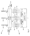
- Fig. 3 is a schematic illustration of the data communication portion of a radio base station 100 and a data communication scheduling system 300 according to an embodiment.
- Three REs 101, 102, 103 are connected to the antenna arrangements 110, 120, 130 through a receiver antenna system multiplexer (RX ASM) 140 and a corresponding transmitter antenna system multiplexer (TX ASM) 150 and through respective antenna interfaces 115, 125, 135.
- the multiplexers 140, 150 are controlled by a receiver controller (RX ctrl) 145 and a transmitter controller (TX ctrl) 155.
- At least one of the receivers 112, 122, 132 and at least one of the transmitters 111, 121, 131 is turned off by a receiver status controller (RX status ctrl) 162 and a transmitter status controller (TX status ctrl) 161, respectively.
- the receiver status controller 162 turns off the power of one of the receivers 132 and the transmitter status controller 161 likewise turns off the power of one of the transmitters 131, preferably arranged in the same RE 103 as the turned off receiver 132.
- two receivers 122, 132 and two transmitters 121, 131 are turned off by the receiver and transmitter status controllers 161,162.
- the operation of the receiver and transmitter status controllers 161, 162 is preferably based at least partly on expected traffic load in the three cells. Thus, if the expected traffic load is at low or moderate levels one or two of the three available receiver-transmitter pairs 121, 131, 122, 132 may indeed be turned off and the remaining receiver-transmitter pair/pairs 111, 112 will be enough to handle the uplink and downlink traffic in the three cells.
- Statistical information based on measurements during different portions of a day, week and/or a month can be collected by the network operator and used as a basis for determining intervals of a day, week and/or month, during which the traffic load is expected to be low enough to allow turning off receiver-transmitter pair/pairs.
- the expected number of user equipment present in the areas of the three cells and requiring communication resources from the radio base station could on average be low enough that the receiver and transmitter status controllers 161, 162 are preconfigured to turn off the power of the selected at least one transmitter 121,131 and receiver 122,132 during the night.
- an optional load estimator 180 can be arranged in the data communication scheduling system 300, preferably in the REC 105. This load estimator 180 estimates the amount of currently buffered data to and from the user equipment in the cells to thereby get an estimate of the traffic status in the cells. If the total amount of data traffic is estimated to be below a traffic threshold, the load estimator 180 signals the receiver and transmitter status controllers 161, 162 to turn off the power of a subset of the transmitters 121, 131 and the receivers 122, 132. The load estimator 180 may optionally have access to multiple different traffic thresholds.
- the receiver and transmitter status controller 161, 162 can turn off the power of a first transmitter 131 and receiver 132 if the estimated traffic load is below a first traffic threshold but exceeds a second traffic threshold. First when the estimated traffic load is below the second traffic threshold will the receiver and transmitter status controllers 161, 162 turn off the power of also the second transmitter 121 and receiver 122, 132.
- the receiver and transmitter status controllers 161, 162 are both implemented in the REC 105 of the data communication scheduling system 300.
- the receiver antenna system multiplexer 140 connects the three receivers 112, 122, 132 with the three antenna interfaces 115, 125, 135 and, when being arranged in the radio base station 100, therefore with the three antenna arrangements 110, 120, 130. Consequently, data captured by the antenna arrangements 110, 120, 130 are forwarded via the antenna interfaces 115, 125, 135 to the correct receiver 112, 122, 132 by the receiver antenna system multiplexer 140.
- the receiver antenna system multiplexer 140 in particular selectively connects the single active receiver 112 to the different antenna interfaces 115, 125, 135 during different sub frames as controlled by the receiver controller 145.
- the transmitter antenna system multiplexer 150 selectively connects the three transmitters 111, 121, 131 with the three antenna interfaces 115, 125, 135 and, when being arranged in the radio base station 100, therefore with the three antenna arrangements 110, 120, 130.
- data from the transmitters 111, 121, 131 is forwarded by the transmitter antenna system multiplexer 150 through the antenna interfaces 115, 125, 135 to the correct antenna arrangement 110, 120, 130.
- the transmitter antenna system multiplexer 150 in particular selectively connects the single active transmitter 111 to the different antenna interfaces 115, 125, 135 during different sub frames as controlled by the transmitter controller 155.
- the transmitter controller 155 consequently controls the transmitter antenna system multiplexer 150 to selectively connect the transmitter 111 to the antenna interfaces 115, 125, 135 so that the respective antenna interface 115, 125, 135 of each of the three cells is connected to the transmitter 111 during at least one sub frame of a radio frame.
- the transmitter 111 is dedicated for processing and forwarding data to each of the three antenna interfaces 115, 125, 135 but in different sub frames.
- the receiver controller 145 controls the receiver antenna system multiplexer 140 to selectively connect the receiver 112 to the three antenna interfaces 115, 125, 135 so that the respective antenna interfaces 115, 125, 135 of each of the three cells is connected to the receiver 112 during at least one sub frame of the radio frame. Furthermore, the sub frame during which the receiver 112 is connected to the antenna interface 115 of a given cell is present at the predefined sub frame distance from the sub frame during which the transmitter 114 is connected to the same antenna interface 115.
- Fig. 14 schematically illustrates a radio frame for the uplink (UL) and the downlink (DL) and the assignment of sub frames to the three different cells denoted A, B and C in the figure.
- the uplink is indicated as one stream.
- LTE normally uses receiver diversity in the uplink.
- the figure merely indicates a single stream in order to simplify the understanding of the embodiments.
- the operations of the receiver and antenna system multiplexers 140, 150 will cause the transmitter 111 and the receiver 112 to be time multiplexed between the three cells.
- Fig. 15 is an example of radio frame structure with time multiplexed uplink and down link transmission for one active RE 101 and three served cells.
- the transmitter 111 sends to each of the cells A, B, C in a respective sub frame 50, 51, 52 that recurs every 5 ms.
- each cell is assigned at least two sub frames 50, 51, 52 for downlink transmission during a radio frame 40 and these correspond to sub frames 0 and 5 in each cell.
- This is preferred distribution of sub frames as today in LTE, PBCH, PSS and SSS appear in sub frames 0 and 5 in each radio frame 40 for a cell.
- the same distribution of control signals within a radio frame 40 as the LTE standard can thereby be achieved.
- sub frame indicated with reference number 50 in the figure corresponds to sub frame 0 for the first cell A.
- sub frame indicated by 51 is interpreted as sub frame 0 for the second cell B and so on.
- the remaining four sub frames 58 in the radio frame 40 can be used arbitrary in the cells and preferably depending on the traffic demand in each cell. However, in order to allow ACK/NACK of downlink traffic, a downlink sub frame 50, 51, 52 assigned for a cell should be accompanied with an uplink sub frame 53, 54, 55 assigned to the same cell four sub frames later.
- the downlink sub frames 50, 51, 52 assigned to the different cells have corresponding uplink sub frames 53, 54, 55 present four sub frames later.
- One of these uplink sub frames 53, 54, 55 can be used for random access (RACH, Random Access Channel) reception in the cell.
- the radio base station 100 In order to also decrease the dynamic power consumption of the radio base station 100, as few of the four remaining sub frames 58 are used possible. Thus, in a minimum load scenario, only six of the ten sub frames in a radio frame 40 are used for communicating data. As the traffic load increases in one or more of the cells, these extra sub frames 58 can be used to serve that traffic.
- extra sub frames can be assigned for the cell in the sub frame before the sub frame 50, 51, 52 carrying the synchronization channels.
- the user equipment has access to two consecutive downlink sub frames to better detect the synchronization channels by averaging the channel estimate. With a single transmitter available and switched between the three different cells, this cannot be accomplished for all the cells. If the radio base stations in the radio communication network are time synchronized to each other, which is common in LTE, the synchronization channels will have a 1/3 reuse, thus reducing the interference and, improving the ability for user equipment to estimate the synchronization channels. As consequence, it is generally not necessary to have two consecutive downlink sub frames per cell.
- the REC 105 will primarily schedule the traffic in each cell on the same sub frame 50, 51, 52 as is transmitting the synchronization channel for that cell. This gives 10 % of the maximum capacity in the cell and >20 % of the average capacity, or even more if the radio base stations are synchronized with 1/3 reuse. If the traffic load is higher extra sub frames 58 can be assigned to the cells. When the traffic load is higher than can be served by one transmitter 111, the transmitter status controller 161 switches on one of the turned off transmitters 121.
- the receiver and antenna system multiplexers 140, 150 should be able to operate on micro second level, thus between sub frames, in order correctly forward data between the active receiver 162 or transmitter 161 and the correct antenna arrangement 110, 120, 130.
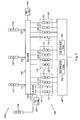
- Fig. 4 is an illustration of the communicating portion of a radio base station 100 and a data communication scheduling system 300 according to another embodiment.
- this data communication scheduling system 300 does not comprise any transmitter antenna system multiplexer. Thus, no selective forwarding of data between a single active transmitter and the three antenna interfaces 115, 125, 135 is conducted in this embodiment.
- the data communication scheduling system 300 instead comprises a so-called multi-cell RE 104 that is primarily used during low load scenarios.
- the multi-cell RE 104 has N TX transmitters 171, one transmitter 171 in the figure.
- the multi-sector RE can have the same requirements on linearity as the normal REs 101, 102, 103 and, thus, be able to transmit traffic at the same characteristics. Alternatively, it is simplified to only be able to transmit lower power and/or low linearity. It would then be able to handle less capacity than the normal REs 101, 102, 103.
- the multi-cell RE 104 preferably has its dedicated antenna interface 175 connectable to a dedicated antenna arrangement 170 in order to remove the need for a transmitter antenna system multiplexer.
- this antenna arrangement 170 is a so-called omnidirectional antenna arrangement 170 capable of radiating power in all the cells served by the radio base station 100. If the combined radio coverage area of the served cells does not cover the full 360° area around the radio base station 100, the antenna arrangement 170 must not necessarily by an omnidirectional antenna but should, however, be able to transmit in the areas of the multiple cells.
- the transmitter controller 155 of the data communication scheduling system 300 has been illustrated implemented in the REC 105 in the figure. This should merely be seen as an illustrative example.
- the transmitter controller 155 could alternatively be arranged in the multi-cell RE 104 or be connected to the REC 105 or the multi-cell RE 104.
- the transmitter controller 155 controls the transmitter 171 to broadcast data relevant for a first cell in all cells during a first sub frame in the radio frame.
- the transmitter 171 is controlled to broadcast data relevant for a second cell in all the cells during a second sub frame in the radio frame, and so on. This basically makes all the cells become one and a same cell.
- the power consumption for dedicated traffic is consequently three times higher.
- the REC 105 or some other unit of the data communication scheduling system 300 can therefore judge when to go from this configuration with a single active multi-cell RE 104 to three active REs 101, 102, 103 and transmitters 111, 121, 131 based on a simple formula: 3 RE: 3 ⁇ Power ( RE static )+ traffic ⁇ Power ( traffic ) ⁇ Efficiency ( RE ) 1 multi-cell RE: 1 ⁇ Power ( RE static )+ traffic ⁇ Power ( traffic ) ⁇ Efficiency ( RE ) ⁇ 3
- the formula can of course be amended based on the number of active transmitters 171 in the multi-cell RE 104 and the number of transmitters 111, 121, 131 in each normal RE 101, 102, 103.
- the operation of the receiver antenna system multiplexer 140 and the receiver controller 145 is basically the same in this embodiment as compared to the embodiment illustrated in Fig. 3 .
- Fig. 4 also illustrates an alternative implementation of the receiver status controller 164, 166, 168 and the transmitter status controller 163, 165, 167.
- each RE 101, 102, 103 can have its dedicated receiver and transmitter status controller 164, 166, 168; 163, 165, 167 for selectively and temporarily turning of the power the receivers 112, 122, 132 and the transmitters 111, 121, 131.
- all the transmitters 111, 121, 131 are preferably turned off and only the transmitter 171 of the multi-cell RE 104 is active if the data communication scheduling is applied to all three cells.
- one of the transmitters 111 can be active if the traffic load in the cell to which the transmitter 111 is dedicated is particularly high as compared to the other two cells in this embodiment.
- the transmitter 171 of the multi-cell RE 104 can be shared between the other two cells and thereby switches between broadcasting data relevant for these two cells.
- one or two of the receivers 122, 132 are turned off by the receiver status controllers 166, 168 so that the remaining receiver or receivers 112 handle all the uplink traffic for the cells as described above in connection with Fig. 3 .
- This means that the antenna gain for the uplink will be same as for normal operation as the active receiver 112 only listens to one antenna arrangement 110, 120, 130 at a time. The same link budget is therefore achieved as for normal operation and the user equipment does not need to increase its output power.
- Fig. 12 schematically illustrates a radio frame for the uplink and the downlink and the assignment of sub frames to the three different cells denoted A, B and C in the figure.
- the downlink transmission is broadcast to all cells, while the receiver is time multiplexed between the cells.
- one uplink sub frame 57 in the radio frame 40 is used for RACH.
- This RACH sub frame 57 should then be able to receive data from all cells, as random access can be transmitted by user equipment in any of the served cells.
- the receiver antenna system multiplexer 140 consequently connects the active receiver 112 to all the antenna interfaces 115, 125, 135 and antenna arrangments 110, 120, 130 dedicated to the cells during this sub frame 57.
- the RACH is very tolerant to the link budget but other uplink traffic scheduled to that sub frame 57 should take the decreased antenna gain into calculation in the link adaptation.
- the scheduling of uplink and downlink sub frames should be configured so that the ACK/NACK of a downlink transmission in a cell is received preferably four sub frames later in the uplink. Therefore, any scheduled transmission in the downlink should be accompanied with a corresponding possibility to receive in the uplink four sub frames later for that cell.
- Fig. 13 illustrates an example where the traffic load is equal in the different cells.
- the radio base station transmits to users in cell A, though in the form of a broadcast transmission that also reaches the other cells B, C.
- the receiver antenna system multiplexer 140 is controlled by the receiver controller 145 to forward data received by the antenna 110 of cell A to the active receiver 112 to thereby be able to receive the ACK/NACK from any user equipment in cell A.
- broadcast transmissions of data destined to any user equipment in cell B and C are carried by sub frames 51, 52 having their scheduled corresponding uplink sub frames 54, 55 at the predefined sub frame distance to receive any ACK/NACK from user equipment.
- the downlink sub frame 56 present the pre-defined sub frame distance prior the RACH sub frame 57 can be used for transmission of data destined in any of the cells or indeed in any combination of two or more cells.
- the downlink sub frame scheduling could be conducted so that the transmission at sub frames X and X + 5 are destined to one and the same cell, thereby corresponding to the sub frames carrying the PBCH, PSS and SSS for the cell.
- two consecutive sub frames can be assigned for transmission of data destined to a same cell for at least some of the cells served by the radio base station 100.
- a new cell is formed covering the coverage area of the M , such as three, cells.
- dedicated system information i.e. information carried by the PBCH, PSS and SSS
- This dedicated system information could be new system information or the system information traditionally used in one of the M cells.
- system information of both this new cell and the M cells could be transmitted on the multi-cell RE with a slow fading out of the signal carrying the system information of the M cells on that RE. A handover between cells can then be handled more safely.
- the channel estimation is generally better.
- time multiplexing in the downlink as in Fig. 3 significantly improves the antenna gain and decreases the interference caused in neighboring cells.
- the dynamic power consumption will also be 1/3 as compared to the omnidirectional downlink transmission.
- implementation of transmitter antenna system multiplexers leads to additional costs as they must be able to affect the switch on a high power signal, i.e. after power amplification. This should be compared to a receiver antenna system multiplexer that performs the switch on low power.
- the cost of the equipment in the transmitter antenna system multiplexer is generally more expensive as compared to the receiver antenna system multiplexer.
- two of the three transmitters 111, 131 can be active so that the transmitter status controller 161 thereby only turns off the power of one of the transmitters 121. It is then possible to schedule two sets of consecutive sub frames for each of the cells as is illustrated in Fig. 16 . These four downlink sub frames 50, 51, 52 that are assigned to the cells therefore correspond to sub frames 0, 4, 5 and 9 in each cell.
- the first active transmitter 111 is then connected between the antenna interface 115 dedicated for the first cell A and the antenna interface 125 of the second cell B.
- the other active transmitter 131 is connected to the antenna interface 135 of the third cell C.
- An advantage of this embodiment is that two antenna multiple-input and multiple-output (MIMO) transmissions can be used for 20-40 % of the sub frames, depending on the particular cell. This will allow maximum usage of time instant of good radio conditions to user equipment.
- MIMO multiple-input and multiple-output
- a natural extension to the embodiment illustrated in Fig. 16 is to also have two active receivers for the radio base station, which is illustrated in Fig. 17 .
- Each set of two consecutive scheduled downlink sub frames 50, 51, 52 can then be followed respective uplink sub frames 53, 54, 55 scheduled four sub frames later than the downlink sub frames 50, 51, 52 for the same cell.
- Figs. 12 to 17 the downlink and uplink transmission are typically conducted using different carrier frequencies. This also applies to Figs. 16 and 17 having two parallel downlink radio frames ( Figs. 16 and 17 ) and two parallel uplink radio frames ( Fig. 17 ). Thus, different downlink and uplink frequencies can be used for the parallel downlink and uplink transmissions, which is well known in the art.
- Figs. 16 and 17 are in particular suitable for a radio base station 100 and data communication scheduling system 300 as illustrated in Fig. 5 having multiple, two in the figure, transmitters 111, 113, 121, 123, 131, 133 and receivers 112, 114, 122, 124, 132, 134 per RE 101, 102, 103.
- only one RE 101 need to be active to provide time multiplexing with two transmitters 111, 113 and/or two receivers 112, 114 using a receiver antenna system multiplexer 140 and transmitter antenna system multiplexer 150.
- each RE 101, 102, 103 only comprises one transmitter 111, 121, 131 and receiver 112, 122, 132 each.
- Each cell then has multiple, two for the example illustrated in Fig. 5 , REs 101, 102, 103 per cell.
- Fig. 5 also illustrates an alternative implementation using an omnidirection antenna arrangement 170.
- no dedicated multi-cell RE is needed but one or more transmitters 111, 113 in one or more of the normal REs 101, 102 are instead connected to the antenna arrangement 170 through the transmitter antenna system multiplexer 150 and the antenna interface 175.
- the receiver status controller 162 and the transmitter status controller 161 turn off the power of the receivers 122, 124, 132, 134 and transmitters 121, 123, 131, 133 in two of the three available REs 102, 103.
- the two remaining active receivers 112, 114 are selectively interconnected to the antenna interfaces 115, 125, 135 dedicated to the cells through the operation of the receiver antenna system multiplexer 140 and the receiver controller 145.
- the transmitter antenna system multiplexer 150 and transmitter controller 155 are arranged for selectively connecting the two active transmitters 111, 113 to the omnidirectional antenna interface 175, while during normal operation they are connected to one of the normal antenna interfaces 115.
- the features of the embodiments illustrated in Figs. 3 to 5 may combine. For instance, usage of multiple receivers 112, 114, 122, 124, 132, 134 and transmitters 111, 113, 121, 123, 131,133 per RE 101, 102, 103 as illustrated in Fig. 5 can be used in any of the data communication scheduling system 300 illustrated in Figs. 3 and 4 . Correspondingly, multiple REs per cell can be applied to any of the embodiments.
- the at least one receiver status controller 162, 164, 166, 168 and the at least one transmitter status controller 161, 163, 165, 167 can be arranged in the REC 105 as in Figs. 3 and 5 or in the REs 101, 102, 103 as in Fig. 4 .
- the load estimator 180 illustrated in Fig. 3 can also be implemented in the data communication scheduling system 300 of Figs. 4 and 5 .
- a separate dedicated omnidirectional antenna arrangement has been used for broadcasting data to the cells served by the radio base station.
- the M antenna arrangements of the radio base stations can be used to thereby simultaneously transmit the same data in all M cells.
- the data communication scheduling system then comprises a transmitter antenna system multiplexer interconnecting the M antenna arrangements through their respective antenna interfaces with the N TX transmitters that are active and used for the data transmission during the low power consumption operation.
- Fig. 23 illustrates one mode TDD defined for LTE TDD.
- a radio frame 40 consists of 3 UL sub frames 53, 6 DL sub frames 50 and 1 special sub frame (SSF) 59A.
- SSF special sub frame
- the first portion of the SSF 59A is used for downlink transmissions and the last portion of the sub frame 59A is employed for uplink transmissions.
- the SSF 59A is the second sub frame in the TDD LTE radio frame 40.
- Today synchronization information intended to user equipment is transmitted in SF0 (A-DL1), part of SF1 (A-SSF), SF5 (A-DL2) and SF6 (A-DL3).
- two cells share radio equipment as is schematically illustrated in Fig. 23 .
- the first cell is denoted A and its traditional radio frame distribution is illustrated in the upper portion of the figure, with the traditional radio frame distribution of the second cell B in the middle portion of the figure.
- This embodiment also takes into consideration that a downlink transmission in SF0 (A-DL1) has a corresponding ACK sent uplink in SF4 (A-UL3) and that an uplink transmission in SF4 (A-UL3) preferably has a corresponding uplink grant transmitted in SF0 (A-DL1).
- the second cell B uses a corresponding relationship between B-DL5 and B-U11.
- Fig. 23 illustrates the radio frame scheduling using one shared radio equipment, i.e. transmitter and receiver, for the two cells.
- One of the sub frames 58 can either be empty or be used in any of the cells. Any further cell of the radio base station would then use one or more other REs.
- a challenge with TDD is that the downlink transmissions from one radio base station will cause interference in the uplink reception in another radio base station. If a neighboring radio base station uses the timing of the cell A in the upper portion of the figure above, it should omit to use the sub frame SF9 (A-DL6) as it would interfere with the reception in cell B.
- HARQ protocol is used according to the LTE standard, user equipment should transmit an ACK in the uplink. According to this standard, this would lead to only having one downlink sub frame per cell to transmit on as only one uplink sub frame 53, 54 exists for the two cells A, B in the radio frame 40 illustrated in Fig. 23 .
- the HARQ protocol for LTE allows for an optimistic link adaptation as retransmissions are fast.
- retransmissions are made 1 frame after the original transmissions and consequently do not affect the embodiments as its frame structure can easily be repeated every radio frame.
- the uplink retransmissions are done 8 sub frames after the initial transmission and the uplink HARQ ACK is expected four time slots or sub frames after every transmission. A missing uplink HARQ ACK leads to a retransmission.
- Fig. 24 illustrates how the HARQ protocol can be applied to an embodiment using LTE FDD mode.
- the HARQ retransmission will limit which sub frames are used in which cells, thereby reducing the flexibility slightly.
- Fig. 24 illustrates the uplink retransmissions scheduling and uplink HARQ ACK/NACK signaling for the sub frames indicated with a, A, b, B, c, C and x.
- sub frame A 50 is regarded as SF0 for cell A
- sub frame B 51 is regarded as SF0 for cell B
- sub frame C 52 is SF0 for cell C.
- the first uplink HARQ ACK/NACK instant for the A sub frame is indicated with A1
- a second, if necessary, instant is indicated with A2 and so on.
- Sub frame A1/c1 denotes the sub frame where either uplink HARQ ACK/NACK for sub frame A or c can be transmitted, etc. Note that an ACK/NACK transmission in cell A cannot be sent when both transmitters are being used for transmission for other cells, B and C, as the three cells share two transmitters in this embodiment.
- Fig. 24 is adapted for the HARQ processing scheme defined in 3GPP release 8.
- teachings of the present embodiments can of course be applied to other HARQ schemes and later revisions of the current LTE HARQ standards.
- the transmitter and receiver antenna system multiplexers map the transmitters and the receivers of the data communication scheduling system to different antenna interfaces.
- the transmitter and receiver antenna system multiplexers can be implemented in many different embodiments depending on the number of antenna interfaces, i.e. the parameter M , the number of REs and the number of transmitters and receivers per RE, i.e. the parameters M TX , M RX , and the number of configurations to support between the minimum configuration, i.e. one transmitter and one receiver for all antenna interfaces, and the maximum configuration, i.e. one RE per antenna interface.
- the transmitter and receiver antenna system multiplexers can be built using units selected among real time controllable radio frequency (RF) switches, RF splitters, RF amplifiers and RF filters.
- RF radio frequency
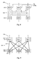
- Fig. 6 is an illustration of an embodiment of a receiver antenna system multiplexer 140.
- This embodiment comprises a respective low noise RF amplifier (LNA) 142 at each antenna input, a respective RF splitter 144 for generating as many copies of the amplified signal from the LNA 142 as there are connected receivers.
- a respective RF multiplexer (MUX) 146 is arranged at the receiver input for selecting one of the antenna signals. These RF multiplexers 146 are controlled on micro second level by the receiver controller as indicated in the figure.
- the receiver antenna system multiplexer 140 therefore comprises M RF amplifiers 142 connected to a respective antenna interface.
- Each RF amplifier 142 is connected to a respective RF splitter 144 arranged for splitting the amplified RF signal from the connected RF amplifier 142 into M RX signal copies.
- M RX RF multiplexers 146 have respective inputs connected to each of the M RF splitters 144 and having a respective output connected to a respective receiver of the M RX receivers in the data communication scheduling system.
- Fig. 7 illustrates an alternative receiver antenna system multiplexer 140 optimized for one shared receiver and remaining receivers, two in this example, operable on a respective dedicated antenna arrangement.
- each antenna interface preferably has a connected low noise RF amplifier 142.
- RF splitters 144 are connected to two of the RF amplifiers 142 and employed for splitting the input amplified RF signal into two signal copies.
- a single RF multiplexer 146 has inputs connected to the RF splitters 144 and directly to the remaining RF amplifier 142 that does not have to, but may, have a RF splitter 144.
- Fig. 8 is an illustration of a transmitter antenna system multiplexer 150 according to an embodiment.
- the transmitter antenna system multiplexer 150 comprises M TX RF multiplexers 156, each connecting to a respective transmitter of the data communication scheduling system.
- a corresponding set of M RF multiplexers 152 or RF filters are connected at the antenna interfaces.
- the two set of multiplexers 152, 156 are interconnected through a combiner network 154, where the output from each transmitter and multiplexer 156 is combined per antenna interface and multiplexer 152.
- the optional set of M RF filters may be used for cleaning the RF signal from any distortion caused by the transmitter antenna system multiplexer 150.
- the RF filters can be combined with the normal transmitter band pass filter to minimize the total loss.
- Fig. 9 is an implementation example of the transmitter antenna system multiplexer 150 illustrated in Fig. 8 .
- the RF multiplexers 156 are implemented as a set of PIN diode switches 159.
- the bold lines 153, 157 in the RF multiplexers 156 and the combiner network 154 represent physical traces with a length corresponding to a fourth of the wavelength. By having these tuned, no RF multiplexers 152 are actually needed on the antenna arrangement sides.
- the figure consequently illustrates the optional RF filters 151 mentioned above to interconnect the combiner network 154 with the antenna interfaces.
- Fig. 10 is an illustration of a transmitter antenna system multiplexer 150 that can be used in connection with broadcasting data to the multiple cells served by the radio base station.
- M RF multiplexers 152 are connected to the respective antenna interfaces.
- N TX RF splitters 158 are arranged in the transmitter antenna system multiplexer 150 so that each RF splitter 158 is interconnected between one of the transmitter-connecting RF multiplexers 156 and the M RF multiplexers 152.
- the respective RF splitter 158 divides the input RF signal into M copies that are sent on the M antenna arrangements to achieve an omni- and broadcast-like transmission of the same data to multiple served cells.
- Fig. 11 illustrates an alternative implementation for a radio base station having six antenna arrangements, three serving cells and two transmitters per cell.
- the transmitter antenna system multiplexer 150 may then be arranged for interconnecting one transmitter per cell with one antenna interface per cell. This means that one antenna arrangement per cell is connected through the transmitter antenna system multiplexer 150 and the other antenna arrangement per cell is directly connected to its transmitter.
- the signals could then by-pass the RF multiplexers 152, 156 and thereby reduces the RF losses.
- the signals are transmitter through the RF multiplexers 152, 156.
- a RE has a static power consumption of 100 W and efficiency for dynamic traffic of 20 %. This means that transmitting X W consumes 5X W. Furthermore, 5 W per cell is used for common channels.
- the transmitter antenna system multiplexer adds another 1.5 dB loss in the transmitter path. This will then decrease the efficiency for dynamic traffic, and to transmit X W, a total of 7X W is consumed.
- the radio base station can serve in different scenarios of RE sharing and the following assumptions can be made:
- the average capacity of a cell is less than 1/3 of the maximum capacity, due to the 1-1 reuse. It can be assumed that no major capacity loss is found if only having the radio resources 1 ⁇ 2 of the time, and a coordinated usage.
- the radio resources can be any of the following two: 1 ⁇ 2 the time, with full power and all frequencies or 1 ⁇ 2 the frequency, with full power and all the time.
- the path loss is proportional to the radius to the power of 3.5, r 3.5 . This is a good first approximation and at evenly distributed traffic, the power needed to serve the traffic, in average, is then:
- the radio base station is assumed to serve three cells, having three REs but each RE comprises two transmitters and two receivers. It is also assumed that two transmitters and two receivers are active and shared between the cells, while the remaining transmitters and receivers are turned off according to the invention.
- the power per cell is 19 W and the total power consumption will be:
- the total power consumed by the radio base station is 10 % lower with the invention and the static power consumption is less than half as compared to the reference case.
- the radio base station is assumed to serve three cells, having three REs but each RE comprises two transmitters and two receivers. It is also assumed that all transmitters and receivers can be shared between the cells. However, only two transmitters and two receivers are active, while the remaining transmitters and receivers are turned off according to the invention. In the reference configuration all six transmitters and receivers are turned on.
- any of the cells can have at maximum 12 out of 20 SF, see Fig. 17 .
- each cell has 1/3 of the transmission resources of one cell.
- this corresponds to about 45 % of the power or 45 W.
- the power per cell is 45 W and the consumption will be:
- onmni- and broadcast-based downlink using a transmitter antenna system multiplexer is useful for sites where the traffic load is assumed to be less than 40 % for the vast majority of the time.
- Time multiplexed downlink using two active transmitters/receivers shared between the three served cells is, however, useful for most sites, as an average load of 65 % can easily be handled.
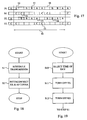
- Fig. 18 is a flow diagram illustrating a method for scheduling data communication by a radio base station as disclosed herein.
- the method starts in step S1, where data transmission is scheduled by the radio base station for the M served cells during a radio frame using N TX transmitters of the M TX transmitters arranged in the radio base station.
- This data transmission scheduling of step S1 is performed so that at least one of the N TX transmitters transmits data destined to user equipment in a first of the M cells during at least one sub frame in the radio frame and transmits data destined to user equipment in a second of the M cells during at least one other sub frame in the radio frame.
- each cell of the M cells is, in the scheduling of step S1, assigned at least one sub frame of the radio frame for transmission of data destined to user equipment in the respective cell.
- a next step S2 selectively connects a receiver of N RX active receivers among M RX receivers arranged in the radio base station to an antenna arrangement of M antenna arrangements arranged in the radio base station.
- This selective interconnecting causes at least one of the N RX receivers to be connected to a first antenna arrangement during at least one sub frame of the radio frame and connected to a second antenna arrangement during at least one other sub frame of the radio frame.
- the selective interconnection causes the antenna arrangement of each cell to be connected to one of the N RX active receivers during at least one sub frame assigned for reception of data for that cell and present at a predefined sub frame distance from the sub frame assigned to that cell for data transmission in step S1.
- the method then ends. It is though expected that the data scheduling method illustrated in Fig. 18 can be repeated for multiple consecutive radio frames. In such a case, the same scheduling and distribution of sub frames for the cells and sharing of transmitters and receivers can be used for all these radio frames. Alternatively, the scheduling can be updated between different radio frames, for instance to take into account increasing traffic demands in one of the cells and/or decreasing traffic demands in one of the cells.
- Fig. 19 is a flow diagram illustrating additional, optional steps of the data communication scheduling method in Fig. 18 .
- the method starts in step S10, where a time interval of day is selected during which at least some of the transmitters and receivers of the radio base station are to be turned off in order to save power.
- This time interval is preferably selected to be an interval, where the expected traffic load is enough to be effectively handled with the remaining transmitter/transmitters and receiver/receivers that are shared between the served cells.
- Statistical evaluations of measured and/or estimated traffic loads during different times of day are preferably used as a basis for selecting the time period in step S10.
- step S11, S12 turn off the power of M TX - N TX transmitters and M RX - N RX receivers to thereby reduce the static power consumption by the radio base station.
- step S1 of Fig. 18 data communication is scheduled using the remaining active M TX transmitters and M RX receivers.
- Fig. 20 is a flow diagram illustrating additional, optional steps of the data communication scheduling method of Fig. 18 .
- the method starts in step S20, where the traffic load in the cells served by the radio base station is estimated. This estimation can, for instance, be based on information available to the MAC scheduler, which is generally aware of the traffic status in the cells, the amount of currently buffered data to and from the served user equipment.
- the estimated traffic load is then compared in step S21 with one or more traffic thresholds for the purpose of determining whether the expected traffic load in the cells is sufficient low to allow turning off at least some of the transmitters and receivers of the radio base station.
- the radio base station can either operate with the full number of transmitters and receivers on or with a fixed number of transmitters and receivers turned off. In such a case, only a single traffic threshold is needed. Examples of such traffic thresholds have been given herein for the particular example situations described in the foregoing. The disclosure in connection with these examples can be used in order to calculate suitable traffic thresholds for other radio base station configurations besides the particular ones given in the examples.
- step S21 multiple traffic thresholds can be used in step S21.
- the total number of transmitters and receivers that can be safely turned off for a current traffic situation is then determined based on the comparisons of the estimated traffic loads and the multiple different traffic thresholds in step S21.
- the selected number of transmitters and receivers are then powered down and turned off in steps S22 and S23.
- the method then continues to step S1 of Fig. 18 , where the data communication of the radio base station is scheduled for the remaining active transmitter/transmitters and receiver/receivers.
- Fig. 21 is a flow diagram illustrating an additional step of the data communication scheduling method. The method continues from step S2 in Fig. 18 .
- a next step S30 broadcasts data destined for user equipment in the served M cells using either an omnidirectional antenna arrangement connected to the active transmitter/transmitters or the M antenna arrangements dedicated for the served cells. In either case, the same data will be sent to all the cells in the relevant sub frames. By switching the data input so that the transmitted data is relevant for different cells during different sub frames, the downlink transmissions for all the cells can be served within a radio frame.
- Fig. 22 is a flow diagram illustrating an additional step of the data communication scheduling method.
- the method starts in step S40, where a transmitter of the N TX active transmitters is selectively connected to an antenna arrangement of the M antenna arrangements according to a scheme so that each served cell has its dedicated antenna arrangement connected to one of the active transmitters during at least one sub frame of the radio frame. This switching of the outputs of active transmitters to the different antenna arrangements achieves sufficient downlink transmissions for the served cells and user equipment.
- the method then continues to step S1 of Fig. 18 , where the data transmission is scheduled for the radio base station.
Landscapes
- Engineering & Computer Science (AREA)
- Computer Networks & Wireless Communication (AREA)
- Signal Processing (AREA)
- Mobile Radio Communication Systems (AREA)
Claims (24)
- Datenkommunikations-Schedulingsystem (300), zur Anordnung in einer Funkbasisstation (100) angepasst, die mindestens M ≥ 2 Zellen (10, 20, 30) versorgt, wobei das Datenkommunikations-Schedulingsystem (300) dadurch gekennzeichnet ist, dass es Folgendes umfasst:mindestens M Antennenschnittstellen (115, 125, 135, 175), jede an eine Antennenanordnung von mindestens M Antennenanordnungen (110, 120, 130, 170) anschließbar;MTX Sender (111, 113, 121, 123, 131, 133, 171), MTX ≥ M;MRX Empfänger (112, 114, 122, 124, 132, 134), MRX ≥ M, wobei mindestens ein Sender der MTX Sender (111, 113, 121, 123,131, 133) und mindestens ein Empfänger der MTX Empfänger (112 114, 122, 124, 132, 134) jeder Zelle der M Zellen (10, 20, 30) zugewiesen sind, wobei jeder Sender der MTX Sender (111, 113, 121, 123, 131, 133, 171) und jeder Empfänger der MRX Empfänger (112, 114, 122, 124, 132, 134) as mindestens eine Antennenschnittstelle der mindestens M Antennenschnittstellen (115, 125, 135, 175) anschließbar ist;einen Sendercontroller (155), angeordnet zum Scheduling von Datenübertragung durch die Funkbasisstation (100) für die M Zellen (10, 20, 30) während eines Funkrahmens (40), der mehrfache Subrahmen (50-58) umfasst, unter Verwendung von NTX Sendern (111,113, 171) der MTX Sender (111, 113, 121, 123, 131, 133, 171), 1 ≤ NTX <MTX , wobei MTX - NTX restliche Sender (121, 123, 131, 133) der MTX Sender (111, 113, 121, 123, 131, 133, 171) während des Funkrahmens (40) ausgeschaltet oder nicht betriebsfähig sind, wobei der Sendercontroller (155) zum Scheduling von mindestens einem Sender (111, 113, 171) der NTX Sender (111, 113, 171) angeordnet ist, um Daten, die für Benutzergeräte (210) in einer ersten Zelle (10) der M Zellen (10, 20, 30) bestimmt sind, während mindestens eines Subrahmens (50) des Funkrahmens (40) zu übertragen und Daten, die für Benutzergeräte (220) in einer zweiten Zelle (20) der M Zellen (10, 20, 30) bestimmt sind, während mindestens eines anderen Subrahmens (51) des Funkrahmens (40) zu übertragen, und der Sendercontroller (155) dazu angeordnet ist, jeder Zelle der M Zellen (10, 20, 30) mindestens einen Subrahmen des Funkrahmens (40) zuzuweisen, um für Benutzergeräte (210, 220, 230) in jeder solchen Zelle bestimmte Daten zu übertragen;einen Empfängerantennensystem-Multiplexer (140), der an mindestens NRX Empfänger (112, 114) aus den MRX Empfängern (112, 114, 122, 124,132, 134), 1 ≤ NRX < MRX, angeschlossen ist, wobei MRX - NRX restliche Empfänger (122, 124, 132, 134) der MRX Empfänger (112, 114, 122, 124, 132, 134) während des Funkrahmens (40) ausgeschaltet oder nicht betriebsfähig sind, und die M Antennenschnittstellen (115, 125, 135) für die M Zellen (10, 20, 30) zugewiesen sind und dazu angeordnet sind, einen Empfänger der NRX Empfänger (112, 114) selektiv an eine Antennenschnittstelle (115) der M Antennenschnittstellen (115, 125,135) anzuschließen; undeinen Empfingercontroller (145), angeordnet zum Steuern des Empfängerantennensystem-Multiplexers (140), um die NRX Empfänger (112, 114) und die M Antennenschnittstellen (115, 125, 135) selektiv zusammenzuschatten, um mindestens einen Empfängers (112, 114) der NRX Empfänger (112, 114) an eine erste Antennenschnittstelle (115) der mindestens M Antennenschnittstellen (115, 125, 135) während mindestens eines Subrahmens (53) des Funkrahmens (40) und an eine zweite Antennenschniustelle (125) der mindestens M Antennenschnittstellen (115, 125, 135) während mindestens eines anderen Subrahmens (54) des Funkrahmens (40) anzuschließen, und für jede Zelle der M Zellen (10, 20, 30) die jeder solchen Zelle zugewiesene Antennenschnittstelle an einen Empfänger der NRX Empfängers (112, 114) während mindestens eines Hubrahmens anzuschließen, der i) für den Empfang von Daten von Benutzergeräten (210, 220, 230) in jeder solchen Zelle zugewiesen wird und ii) mit einer vorgegebenen Subrahmen-Entfemung vom mindestens einen Subrahmen vorhanden ist, der vom Sendereontroller (155) jeder solchen Zelle zugewiesen wird.
- Datenkommunikations-Schedulingsystem nach Anspruch 1, worin der Sendereontroller (155) zum Scheduling der Datenübertragung durch die Funkbasisstation (100) für die M Zellen (10, 20, 30) während des Funkrahmens (40) unter Verwendung der NTX Sender (111, 113, 171) angeordnet ist, um jeder Zelle der M Zellen (10, 20, 30) mindestens einen ersten Subrahmen und einen zweiten Hubrahmen zuzuweisen, die im Funkrahmen (40) an fünf Subrahmen vorhanden sind, die dem ersten Subrahmen zur Übertragung der für die Benutzergeräte (210, 220, 230) in jeder solchen Zelle bestimmten Daten nachfolgen.
- Datenkommunikations-Schedulingsystem nach Anspruch 1 oder 2, worin der Sendercontrotler (155) zum Scheduling der Datenübertragung durch die Funkbasisstation (100) für die M Zellen (10, 20, 30) während des Funkrahmens (40) unter Verwendung von zwei Sendern (111, 113) angeordnet ist, um jeder der M > 2 Zellen (10, 20, 30) mindestens zwei aufeinanderfolgende Subrahmen des Funkrahmens (40) zur Übertragung der für die Benutzergeräte (210, 220, 230) in jeder solchen Zelle bestimmten Daten, zuzuweisen.
- Datenkommunikations-Schedulingsystem nach Anspruch 3, worin der Empfängercontroller (145) zum Steuern des Empfängerantennensystem-Multiplexers (140) angeordnet ist, um die NRX Empfänger (112, 114) und die M Antennenschnittstellen (115, 125, 135) selektiv zusammenzuschalten, um für jede der M Zellen (10, 20, 30) die jeder solchen Zelle zugewiesene Antennenschnittstelle an Empfänger der zwei Empfänger (112, 114) während mindestens zweier aufeinanderfolgender Subrahmen anzuschließen, die i) für den Empfang der Daten von den Benutzergeräten (210, 220, 230) in jeder solchen Zelle zugewiesen werden und ii) mit der vorgegebenen Subrahmen-Entfernung von den mindestens zwei Hubrahmen vorhanden sind, die vom Sendercontroller (155) jeder solchen Zelle zugewiesen werden.
- Datenkommunikations-Schedulingsystem nach einem der Ansprüche 1 bis 4, worin der Empfängercontroller (145) zum Steuern des Empfängerantennensystem-Multiplexers (140) angeordnet ist, um die NRX Empfänger (112, 114) und die M Antennenschnittstellen (115, 125, 135) selektiv zusammenzuschalten, um für jede der M Zellen (10, 20, 30) die jeder solchen Zelle zugewiesene Antennenschnittstelle an einen Empfängers der NRX Empfänger (112, 114) während mindestens eines Subrahmens anzuschließen, der i) für den Empfang der Daten von den Benutzergeräten (210, 220, 230) in jeder solchen Zelle zugewiesen wird und ii) im Funkrahmen vorhanden ist, wobei vier Hubrahmen dem mindestens einen Subrahmen nachfolgen, der vom Sendercontroller (155) jeder solchen Zelle zugewiesen wird.
- Datenkommunikations-Schedulingsystem nach einem der Ansprüche 1 bis 5, außerdem umfassend:einen Senderstatuscontroller (161, 163, 165, 167), dazu angeordnet, die MTX - NTX restlichen Sender (121, 123, 131, 133) der MTX Sender (111, 113, 121, 123, 131, 133, 171) auszuschalten; undeinen Empfangerstatuscontroller (162, 164, 166, 168), dazu angeordnet, die MRX - NRX restlichen Empfänger (122, 124, 132, 134) der MRX (Empfänger (112, 114, 122, 124, 132, 134) auszuschalten.
- Datenkommunikations-Schedulingsystem nach Anspruch 6, worin der Senderstatuscontroller (161, 163, 165, 167) und der Empfangerstatuscontroller (162, 164, 166, 168) dazu angeordnet sind, die MTX - NTX restlichen Sender (121, 123, 131, 133) und die MRX - NRX restlichen Empfängers (122, 124, 132, 134) an einem vorgegebenen Zeitintervall eines Tages aufzuschalten.
- Datenkommunikations-Schedulingsystem nach Anspruch 6 oder 7, außerdem einen Lastschätzer (180) umfassend, der zum Erzeugen eines Steuersignals angeordnet ist, falls eine geschätzte erwartete Datenverkehrslast in den M Zellen (10, 20, 30) während eines Zeitintervalls unter einer Verkehrsschwelle liegt, worin der Senderstatuscontroller (161, 163, 165, 167) und der Empfängerstatuscontroller (162, 164, 166, 168) reaktionsfähig auf das Steuersignal sind und die MTX - NTX restlichen Sender (121, 123, 131, 133) und die MRX - NRX restlichen Empfänger (122, 124, 132, 134) auf der Basis des Steuersignals ausschalten.
- Datenkommunikations-Schedulingsystem nach einem der Anspruche 1 bis 8, worin die NTX Sender (171) zum Rundsenden von für die Benutzergeräte (210, 220, 230) in den M Zellen (10, 20, 30) bestimmten Daten angeordnet sind, unter Verwendung einer Rundstrahlantennenanordnung (170), die an eine Antennenschnittstelle (175) der mindestens M Antennenschnittstellen (115, 125, 135, 175) an den Subrahmen der mehrfachen Subrahmen (50-55) anschließbar ist, die zur Übertragung der Daten vom Sendercontroller (155) zugewiesene sind.
- Datenkommunikations-Schedulingsystem nach einem der Anspruche 1 bis 9, außerdem einen Senderantennensystem-Multiplexer (150) umfassend, der mindestens an die NTX Sender (111, 113) und die M Antennenschnittstellen (115, 125, 135) angeschlossen ist und dazu angeordnet ist, einen Sender der NTX Sender (111, 113) selektiv an eine Antennenschnittstelle der M Antennenschnittstellen (115, 125, 135) anzuschließen, worin der Sendercontroller (155) dazu angeordnet ist, den Senderantennensystem-Multiplexer (150) zu steuern, um die NTX Sender (111, 113) und die M AntenncnsehnitLstellen (115, 125, 135) selektiv zusammenzuschalten, um für jede Zelle der M Zellen (10, 20, 30) die jeder solchen Zelle zugewiesene Antennenschnittstelle während des mindestens einen Subrahmens, der zur Übertragung der für die Benutzergeräte (210, 220, 230) in jeder solchen Zelle bestimmten Daten zugewiesen wird, an einen Sender der NTX Sender (111, 113) anzuschließen.
- Datenkommunikations-Schedulingsystem nach Anspruch 10, worin der Senderantennensystem-Multiplexer (150) umfasst:MTX Funkfrequenzmultiplexer (156), deren jeder an einen jeweiligen Sender der MTX Sender (111, 113, 121, 123,131, 133) angeschlossen ist;M Funkfrequenzfilter (151), deren jedes an eine jeweilige Antennenschnittstelle der M Antennenschnittstellen (115, 125, 135) angeschlossen ist; undein Kombinatornetz (154), das jedes Funkfrequenzfilter der M Funkfrequcnzfilter (151) mit jedem Funkfrequenzmultiplexer der MTX Funkfrequenzmultiplexer (156) zusammenschaltet.
- Datenkommunikations-Schedulingsystem nach Anspruch 10, worin der Senderantennensystem-Multiplexer (150) umfasst:M erste Funkfrequenzmultiplexer (152), an eine jeweilige Antemenschnittstelle der der M Antennenschnittstellen (115, 125, 135) angeschlossen;NTX zweite Funkfrequenzmultiplexer (156), an einen jeweiligen Sender der NTX Sender (111, 113) und einen jeweiligen ersten Funkfrequenzmultiplexer der M ersten Funkirequenzmultiplexer (152) angeschlossen, undNTX Funkfrequenzsplitter (158), an einen jeweiligen zweiten Funkfrequenzmultiplexer der NTX zweiten Funkfrequenzmultiplexer (156) und die M ersten Funkfrequenzmultiplexer (152) angeschlossen.
- Datenkommunikations-Schedulingsystem nach einem der Anspruche 1 bis 12, worin der Empfängerantennensystem-Multiplexer (140) umfasst:M Funkfrequenzverstärker (142), an eine jeweilige Antennenschfliustelle der M Antennenschnittstellen (115, 125, 135) angeschlossen;M Funkfrequenzsplitter (144), an einen jeweiligen Funkfrequenzverstärker der M Funkfrequenzverstarker (142) angeschlossen und zum Splitten eines verstärkten Funkfrequenzsignals in MRX Signalkopien angeordnet; undMRX Funkfrequenzmultiplexer (146), an einen jeweiligen Empfänger der MRX Empfänger (112, 114, 122, 124, 132, 136) und die M Funkfrequenzsplitter (144) angeschlossen.
- Funkbasisstation (100), Folgendes umfassend:mindestens M Antennenanordnungen (110, 120, 130, 170); undein Datenkommunikations-Schedulingsystem (300) nach einem der Ansprüche 1 bis 13, worin jedes der mindestens M Antennenanordnungen (110, 120, 130, 170) an eine jeweilige Antennenschnittstelle (115, 125, 135, 175) des Datenkommunikations-Schedulingsystems (300) angeschlossen ist.
- Verfahren zum Scheduling von Datenkommunikation durch eine Funkbasisstation (100), die mindestens M ≥ 2 Zellen (10, 20, 30) versorgt und Folgendes umfasst: mindestens M Antennenanordnungen (110, 120, 130, 170), MTX Sender (111, 113, 121, 123, 131, 133, 171), MTX ≥ M, und MRX Empfänger (112, 114, 122, 124, 132, 134), MRX ≥ M, wobei jeder Zelle der M Zellen (10, 20, 30) mindestens ein Sender der MTX Sender (111, 113, 121, 123, 131, 133), mindestens ein Empfänger der MRX Empfänger (112, 114, 122, 124, 132, 134) und eine Antennenanordnung der mindestens M Antennenanordnungen (110, 120, 130) zugewiesen wird, wobei jeder Sender der MTX Sender (111, 113, 121, 123, 131, 133, 171) an mindestens eine Antennenanordnung der mindestens M Antennenanordnungen (110, 120, 130, 170) anschließbar ist und jeder Empfänger der MRX Empfänger (112, 114, 122, 124, 132, 134) an mindestens eine Antennenanordnung der mindestens M Antennenanordnungen (110, 120, 130) anschließbar ist, wobei das Verfahren durch die folgende Schritte gekennzeichnet ist:
durch Scheduling von Datenübertragung durch die Funkbasisstation (100) für M Zellen (10, 20, 30) während eines Funkrahmens (40), der mehrfache Subrahmen (50-58) umfasst, unter Verwendung von NTX Sendern (111, 113, 171) der MTX Sender (111, 113, 121, 123, 131, 133, 171), 1 ≤ NTX < MTX , wobei MTX - NTX restliche Sender (121,123, 131, 133) der MTX Sender (111, 113, 121, 123, 131, 133, 171) während des Funkrahmens (40) ausgeschaltet oder nicht betriebsfähig sind, durch Scheduling von mindestens einem Sender (111, 113, 171) der NTX Sender (111, 113, 171), um Daten, die für Benutzergeräte (210) in einer ersten Zelle (10) der M Zellen (10, 20, 30) bestimmt sind, während mindestens eines Subrahmens (50) des Funkrahmens (40) zu übertragen und Daten, die für Benutzergeräte (220) in einer zweiten Zelle (20) der M Zellen (10, 20, 30) bestimmt sind, während mindestens eines anderen Subrahmens (51) des Funkrahmens (40) zu übertrafen, und durch Zuweisen an jede Zelle der M Zellen (10, 20, 30) von mindestens einem Subrahmen des Funkrahmens (40) zur Übertragung von Daten, die für Benutzergeräte (210, 220, 230) in jeder solchen Zelle bestimmt sind; und
selektives Anschließen eines Empfängers von NRX Empfängern (112, 114) aus den MRX Empfängern (112, 114, 122, 124, 132, 134), 1 ≤ NRX < MRX , wobei MRX - NRX restliche Empfänger (122, 124, 132, 134) der MRX Empfänger (112, 114, 122, 124, 132, 134) während des Funkrahmens (40) ausgeschaltet oder nicht betriebsfähig sind, an eine Antennenanordnung der M Antennenanordnungen (110, 120,130) durch Abschließen von mindestens einem Empfänger (112, 114) der NRX Empfänger (112, 114) an eine erste Antennenanordnung (110) der M Antennenanordnungen (110, 120, 130) während mindestens eines Subrahmens (53) des Funkrahmens (40) und an eine zweite Antennenanordnung (120) der M Antennenanordnungen (110, 120, 130) während mindestens eines anderen Subrahmens (54) des Funkrahmens (40) und durch Abschließen für jede Zelle der M Zellen (10, 20, 30) der jeder solchen Zelle zugewiesenen Antennenanordnung an einen Empfänger der NRX Empfänger (112, 114) während mindestens eines Subrahmens, der i) für den Empfang von Daten von den Benutzergeräten (210, 220, 230) in jeder solchen Zelle zugewiesene wird und ii) mit einer vorgegebenen Subrahmen-Entfernung vom mindestens einen Subrahmen vorhanden ist, der jeder solchen Zelle zur Übertragung von Daten zugewiesen wird. - Verfahren nach Anspruch 15, worin der Schritt des Scheduling von Datenübertragung das Scheduling der Datenübertragung durch die Funkbasisstation (100) für die M Zellen (10, 20, 30) während des Funkrahmens (40) unter Verwendung der NTX Sender (111, 131, 171) umfasst, indem jeder Zelle der M Zellen (10, 20, 30) mindestens ein erster Subrahmen und ein zweiter Subrahmen zugewiesen wird, die im Funkrahmen (40) an fünf Subrahmen vorhanden sind, die dem ersten Subrahmen zur Übertragung der für die Benutzergeräte (210, 220, 230) in jeder solchen Zelle bestimmten Daten nachfolge.
- Verfahren nach Anspruch 15 oder 16, worin der Schritt des Scheduling von Datenübertragung das Scheduling der Datenübertragung durch die Funkbasisstation (100) für die M Zellen (10, 20, 30) während des Funkrahmens (40) unter Verwendung von zwei Sendern (111, 113) umfasst, indem jeder Zelle der M > 2 Zellen (10, 20, 30) mindestens zwei aufeinanderfolgende Subrahmen des Funkrahmens (40) zur Übertragung der für die Benutzergeräte (210, 220, 230) in jeder solchen Zelle bestimmten Daten zugewiesen werden.
- Verfahren nach Anspruch 17, worin der Schritte des selektiven Anschließens eines Empfängers das selektive Abschließen des Empfängers der NRX Empfänger (112, 114) an die Antennenanordnung der M Antennenanordnungen (110, 120, 130) umfasst, indem für jede Zelle der M Zellen (10, 20, 30) die jeder solchen Zelle zugewiesene Anteunenschnittstelle an einen Empfänger von zwei Empfänger (112, 114) während mindestens zweier aufeinanderfolgender Subrahmen angeschlossen wird, die i) für den Empfang der Daten von den Benutzergeräten (210, 220, 230) in jeder solchen Zelle zugewiesen sind und ii) mit einer vorgegebenen Subrahmen-Entfemung von den mindestens zwei Subrahmen vorhanden sind, die jeder solchen Zelle zur Übertragung von Daten zugewiesen wird.
- Verfahren nach einem der Anspruche 15 bis 18, worin der Schritt des selektiven Anschließens eines Empfängers das selektive Anschließen des Empfängers der NRX Empfänger (112, 114) an die Antennenanordnung der M Antennenanordnungen (110, 120, 130) umfaßt, indem für jede Zelle der M Zellen (10, 20, 30) die jeder solchen Zelle zugewiesene Antennenanordnung an einen Empfänger der NRX Empfängers (112, 114) während mindestens eines Subrahmens angeschlossen wird, der i) für den Empfang der Daten von den Benutzergeräten in jeder solchen Zelle zugewiesen wird und ii) im Funkrahmen vorhanden ist, wobei vier Subrahmen dem mindestens einen Subrahmen nachfolgen, der jeder solchen Zelle zur Übertragung von Daten zugewiesen wird.
- Verfahren nach einem der Ansprüche 15 bis 19, außerdem folgende Schritte umfassend:Ausschalten der MTX - NTX restlichen Sender (121, 123, 131, 133) der MTX Sender (111, 113, 121, 123, 131, 133, 171); undAusschalten der MRX - NRX restlichen Empfänger (122, 124, 132, 134) der MRX Empfänger (112, 114, 122, 124, 132, 134).
- Verfahren nach Anspruch 20, worin die Schritte des Ausschaltens der MTX - NTX restlichen Sender (121, 123, 131, 133) und der MRX - NRX restlichen Empfänger (122, 124, 132, 134) an einem vorgegebenen Zeitintervall eines Tages ausgeführt werden.
- Verfahren nach Anspruch 20 oder 21, außerdem den Schritt umfassend, eine erwartete Datenverkehrslast in den M Zellen (10, 20, 30) während eines Zeitintervalls zu schätzen, worin die Schritte des Ausschaltens der MTX - NTX restlichen Sender (121, 123, 131, 133) und der MRX - NRX restlichen Empfänger (122, 124, 132, 134) getriggert werden, falls die erwartete Datenverkehrslast unter einer Verkehrsschwelle liegt.
- Verfahren nach einem der Ansprüche 15 bis 22, außerdem den Schritt umfassend, dass die NTX Sender (171) für die Benutzergeräte (210, 220, 230) in den M Zellen (10, 20, 30) bestimmte Daten unter Verwendung einer an die NTX Sender (171) angeschlossenen Rundstrahlantennenanordnung (170) an den Subrahmen des Funkrahmens (40) rundsenden, die zum Übertragen der Daten zugewiesen sind.
- Verfahren nach einem der Ansprüche 15 bis 23, worin der Schritt des Scheduling von Datenübertragung umfasst, dass ein Sender der NTX Sender (111, 113) an eine Antennenanordnung der M Antennenanordnungen (110, 120, 130) selektiv angeschlossen wird, indem für jede Zelle der M Zellen (10, 20, 30) die jeder solchen Zelle zugewiesene Antennenanordnung an einen Sender der NTX Sender (111, 113) während des mindestens einen Subrahmens angeschlossen wird, der zum Übertragen der für die Benutzergeräte (210, 220, 230) in jeder solchen Zelle bestimmten Daten zugewiesen wird.
Applications Claiming Priority (1)
| Application Number | Priority Date | Filing Date | Title |
|---|---|---|---|
| PCT/SE2009/050370 WO2010117313A1 (en) | 2009-04-08 | 2009-04-08 | Data communication scheduling |
Publications (2)
| Publication Number | Publication Date |
|---|---|
| EP2417802A1 EP2417802A1 (de) | 2012-02-15 |
| EP2417802B1 true EP2417802B1 (de) | 2013-03-20 |
Family
ID=41560086
Family Applications (1)
| Application Number | Title | Priority Date | Filing Date |
|---|---|---|---|
| EP09788521A Active EP2417802B1 (de) | 2009-04-08 | 2009-04-08 | Datenkommunikations-scheduling |
Country Status (4)
| Country | Link |
|---|---|
| US (1) | US8626088B2 (de) |
| EP (1) | EP2417802B1 (de) |
| CN (1) | CN102461280B (de) |
| WO (1) | WO2010117313A1 (de) |
Families Citing this family (33)
| Publication number | Priority date | Publication date | Assignee | Title |
|---|---|---|---|---|
| US8201205B2 (en) | 2005-03-16 | 2012-06-12 | Tvworks, Llc | Upstream bandwidth management methods and apparatus |
| US9622169B2 (en) * | 2010-01-04 | 2017-04-11 | Nec Corporation | Power-save operation supporting apparatus, power-save operation supporting method, storage medium and base station |
| US20120315948A1 (en) * | 2010-02-24 | 2012-12-13 | Telefonaktiebolaget Lm Ericsson (Publ) | Method and Apparatus for Controlling Energy Consumption in a Multi-Antenna Base Station |
| KR20110114175A (ko) * | 2010-04-13 | 2011-10-19 | 삼성전자주식회사 | 광대역 무선통신 시스템에서 전력 소비 감소를 위한 장치 및 방법 |
| CN102378323B (zh) | 2010-08-13 | 2014-12-10 | 电信科学技术研究院 | 一种节能补偿方法及基站 |
| GB2484347A (en) * | 2010-10-08 | 2012-04-11 | Nec Corp | Initiating energy saving mode based on the activity of mobile communications equipment over an LTE-A interface |
| US9252874B2 (en) | 2010-10-13 | 2016-02-02 | Ccs Technology, Inc | Power management for remote antenna units in distributed antenna systems |
| US9160449B2 (en) | 2010-10-13 | 2015-10-13 | Ccs Technology, Inc. | Local power management for remote antenna units in distributed antenna systems |
| WO2012059128A1 (en) | 2010-11-03 | 2012-05-10 | Telefonaktiebolaget L M Ericsson (Publ) | Repeater device |
| US11296504B2 (en) | 2010-11-24 | 2022-04-05 | Corning Optical Communications LLC | Power distribution module(s) capable of hot connection and/or disconnection for wireless communication systems, and related power units, components, and methods |
| EP2643947B1 (de) | 2010-11-24 | 2018-09-19 | Corning Optical Communications LLC | Stromverteilungsmodul(e) mit heissstart- und/oder stoppfunktion für verteilte antennensysteme und zugehörige aggregate, komponenten, und verfahren |
| US20140051433A1 (en) * | 2011-03-07 | 2014-02-20 | Otmar Rengert | Method and an apparatus for reducing energy consumption in a base station of a corrdless telephone |
| US8750187B2 (en) * | 2011-05-13 | 2014-06-10 | Qualcomm Incorporated | Data driven adaptive receive chain diversity processing |
| US20120300710A1 (en) * | 2011-05-27 | 2012-11-29 | Nokia Siemens Networks Oy | Distributing L2 Baseband Processing in a Radio Network |
| EP2721880B1 (de) * | 2011-06-16 | 2019-01-16 | Telefonaktiebolaget LM Ericsson (publ) | Verfahren und anordnung bei einem netzwerkknoten |
| WO2012175133A1 (en) * | 2011-06-22 | 2012-12-27 | Telefonaktiebolaget L M Ericsson (Publ) | Adaptive filtering architecture |
| US11323337B2 (en) | 2011-09-27 | 2022-05-03 | Comcast Cable Communications, Llc | Resource measurement and management |
| US8797852B2 (en) * | 2012-06-11 | 2014-08-05 | Alcatel Lucent | Dynamical bandwidth adjustment of a link in a data network |
| US9154222B2 (en) | 2012-07-31 | 2015-10-06 | Corning Optical Communications LLC | Cooling system control in distributed antenna systems |
| CN102833831A (zh) * | 2012-08-21 | 2012-12-19 | 中兴通讯股份有限公司 | 实现动态休眠和唤醒的网卡设备、路由设备、系统及方法 |
| US9166690B2 (en) * | 2012-09-25 | 2015-10-20 | Corning Optical Communications LLC | Power distribution module(s) for distributed antenna systems, and related power units, components, systems, and methods |
| US10257056B2 (en) | 2012-11-28 | 2019-04-09 | Corning Optical Communications LLC | Power management for distributed communication systems, and related components, systems, and methods |
| WO2014116811A1 (en) * | 2013-01-25 | 2014-07-31 | Mediatek Singapore Pte. Ltd. | Sectorization feedback and multi-sector transmission in wireless networks |
| US9106557B2 (en) | 2013-03-13 | 2015-08-11 | Comcast Cable Communications, Llc | Scheduled transmission of data |
| CN105122704B (zh) * | 2013-04-18 | 2018-02-23 | Lg 电子株式会社 | 在无线接入系统中发送调度请求的方法和设备 |
| EP3039814B1 (de) | 2013-08-28 | 2018-02-21 | Corning Optical Communications Wireless Ltd. | Leistungssteuerung für verteilte kommunikationssysteme sowie entsprechende komponenten, systeme und verfahren |
| WO2015079435A1 (en) | 2013-11-26 | 2015-06-04 | Corning Optical Communications Wireless Ltd. | Selective activation of communications services on power-up of a remote unit(s) in a distributed antenna system (das) based on power consumption |
| US9785175B2 (en) | 2015-03-27 | 2017-10-10 | Corning Optical Communications Wireless, Ltd. | Combining power from electrically isolated power paths for powering remote units in a distributed antenna system(s) (DASs) |
| CN108282165B (zh) * | 2017-12-25 | 2021-08-17 | 中国电子科技集团公司电子科学研究院 | 一种无线通信系统架构 |
| WO2019174046A1 (zh) * | 2018-03-16 | 2019-09-19 | 北京小米移动软件有限公司 | 定义小区同步广播块位置的指示、搜索方法及装置和基站 |
| US20230388922A1 (en) * | 2020-09-16 | 2023-11-30 | Telefonaktiebolaget Lm Ericsson (Publ) | Radio network node and method performed therein for power control |
| EP4213525A4 (de) * | 2020-11-02 | 2024-03-27 | Samsung Electronics Co., Ltd. | Verfahren zur steuerung einer vielzahl von zellen zur bereitstellung von drahtlosen ressourcen an mehrere endgeräte und elektronische vorrichtung zur durchführung davon |
| WO2023274523A1 (en) * | 2021-06-30 | 2023-01-05 | Telefonaktiebolaget Lm Ericsson (Publ) | A communication node for adaptively controlling power consumption |
Family Cites Families (17)
| Publication number | Priority date | Publication date | Assignee | Title |
|---|---|---|---|---|
| EP0947108A2 (de) | 1996-12-09 | 1999-10-06 | Siemens Aktiengesellschaft | Basisstation für ein funk-kommunikationssystem |
| FI108764B (fi) * | 1997-05-28 | 2002-03-15 | Nokia Corp | Solukkoradiojärjestelmän lähetinvastaanotinyksiköiden ohjaus |
| JP3119605B2 (ja) | 1997-10-28 | 2000-12-25 | 埼玉日本電気株式会社 | 無線基地局 |
| KR20000002504A (ko) * | 1998-06-20 | 2000-01-15 | 윤종용 | 이동통신 시스템의 선택적 송신 다이버시티 장치 및 방법 |
| US6584330B1 (en) * | 2000-07-18 | 2003-06-24 | Telefonaktiebolaget Lm Ericsson (Publ) | Adaptive power management for a node of a cellular telecommunications network |
| EP1733579B1 (de) * | 2003-12-19 | 2008-03-19 | Telefonaktiebolaget LM Ericsson (publ) | Adaptive leistungssteuerung für einen knoten eines telekommunikationsnetzwerks |
| CN101313548B (zh) * | 2005-09-27 | 2013-06-05 | 诺基亚公司 | 用于在多载波系统的传输内布置导频序列的方法和装置 |
| CN101185200B (zh) * | 2005-11-14 | 2011-07-20 | 桥扬科技有限公司 | 用于蜂窝通信和广播的多天线系统 |
| EP2375585B1 (de) * | 2006-10-31 | 2018-10-10 | Qualcomm Incorporated | Vereinigter Entwurf und zentralisierte Einplanung für dynamischen SIMO-, SU-MIMO- und MU-MIMO-Betrieb für Funkübertragungen |
| JP2010516208A (ja) * | 2007-01-11 | 2010-05-13 | クゥアルコム・インコーポレイテッド | 無線通信システムにおいてdtxおよびdrxを使用すること |
| US8498639B2 (en) * | 2007-02-09 | 2013-07-30 | Qualcomm Incorporated | Flexible channel quality indicator reporting |
| US7797013B2 (en) | 2007-02-28 | 2010-09-14 | Telefonaktiebolaget Lm Ericsson (Publ) | Radio communications using scheduled power amplifier backoff |
| US8908581B2 (en) * | 2007-05-01 | 2014-12-09 | Qualcomm Incorporated | Extended microsleep for communications |
| US20080287163A1 (en) * | 2007-05-17 | 2008-11-20 | Telefonaktiebolaget Lm Ericsson (Publ), | Method and apparatus for converting between a multi-sector, omni-base station configuration and a multi-sector base station configuration |
| EP2120493A1 (de) * | 2008-03-19 | 2009-11-18 | Nokia Siemens Networks Oy | Mechanismus für automatisierte Rekonfigurierung eines Zugangsnetzelements |
| US8340199B2 (en) * | 2008-10-27 | 2012-12-25 | Samsung Electronics Co., Ltd. | 8-transmit antenna reference signal design for downlink communications in a wireless system |
| US9026124B2 (en) * | 2009-03-31 | 2015-05-05 | Futurewei Technologies, Inc. | System and method for interference mitigation in a wireless communications system |
-
2009
- 2009-04-08 EP EP09788521A patent/EP2417802B1/de active Active
- 2009-04-08 WO PCT/SE2009/050370 patent/WO2010117313A1/en not_active Ceased
- 2009-04-08 CN CN200980159854.1A patent/CN102461280B/zh not_active Expired - Fee Related
- 2009-04-08 US US13/263,207 patent/US8626088B2/en not_active Expired - Fee Related
Also Published As
| Publication number | Publication date |
|---|---|
| CN102461280B (zh) | 2015-02-04 |
| EP2417802A1 (de) | 2012-02-15 |
| CN102461280A (zh) | 2012-05-16 |
| WO2010117313A1 (en) | 2010-10-14 |
| US20120063377A1 (en) | 2012-03-15 |
| US8626088B2 (en) | 2014-01-07 |
Similar Documents
| Publication | Publication Date | Title |
|---|---|---|
| EP2417802B1 (de) | Datenkommunikations-scheduling | |
| EP2737758B1 (de) | Verfahren zur ressourcenverwaltung in einem mobilfunknetz und ressourcenverwaltungssystem | |
| US8565827B2 (en) | Method and apparatus for power saving in wireless communication node B | |
| KR101546641B1 (ko) | 협력적 무선 통신을 위한 방법 및 장치 | |
| US8515495B2 (en) | MIMO communication system | |
| US8538352B2 (en) | Radio base transceiver station and power supplying method | |
| TWI517733B (zh) | 分佈無線通訊上鏈功率控制 | |
| EP2190234B1 (de) | Basisstation und verfahren zur abdeckung mehrerer bereiche durch eine funkzelle | |
| CN102917460B (zh) | 一种时分复用发射通道的方法及系统 | |
| EP3824678B1 (de) | Energieeinsparung in entfernten funkköpfen | |
| JP2007534241A (ja) | リソースを集中的に制御する分散無線システム | |
| CN104412535A (zh) | 用于多用户mimo调度的方法和节点 | |
| US12414048B2 (en) | Increased uplink power for radio frequency communication | |
| JP6232991B2 (ja) | 無線アクセスシステム,及び無線制御装置 | |
| US20100086070A1 (en) | User apparatus, base station apparatus, mobile communication system and communication control method | |
| CN1953347B (zh) | 无线信号发送、接收方法及系统 | |
| JP2011166806A (ja) | 移動体通信システム、基地局制御装置及び移動端末 | |
| US9191901B2 (en) | Radio base station and power control method | |
| EP2856800B1 (de) | Verfahren und vorrichtungen in einem kommunikationssystem | |
| KR20260009595A (ko) | 무선 통신 시스템에서 네트워크 에너지 절약을 위한 통신 장치의 제어 방법 및 장치 | |
| KR20260009594A (ko) | 무선 통신 시스템에서 통신 장치의 전력 제어 방법 및 장치 |
Legal Events
| Date | Code | Title | Description |
|---|---|---|---|
| PUAI | Public reference made under article 153(3) epc to a published international application that has entered the european phase |
Free format text: ORIGINAL CODE: 0009012 |
|
| 17P | Request for examination filed |
Effective date: 20111014 |
|
| AK | Designated contracting states |
Kind code of ref document: A1 Designated state(s): AT BE BG CH CY CZ DE DK EE ES FI FR GB GR HR HU IE IS IT LI LT LU LV MC MK MT NL NO PL PT RO SE SI SK TR |
|
| DAX | Request for extension of the european patent (deleted) | ||
| REG | Reference to a national code |
Ref country code: DE Ref legal event code: R079 Ref document number: 602009014270 Country of ref document: DE Free format text: PREVIOUS MAIN CLASS: H04W0052020000 Ipc: H04W0072120000 |
|
| GRAP | Despatch of communication of intention to grant a patent |
Free format text: ORIGINAL CODE: EPIDOSNIGR1 |
|
| RIC1 | Information provided on ipc code assigned before grant |
Ipc: H04W 52/02 20090101ALN20120919BHEP Ipc: H04W 72/12 20090101AFI20120919BHEP Ipc: H04W 88/08 20090101ALN20120919BHEP |
|
| RIC1 | Information provided on ipc code assigned before grant |
Ipc: H04W 52/02 20090101ALN20120924BHEP Ipc: H04W 72/12 20090101AFI20120924BHEP Ipc: H04W 88/08 20090101ALN20120924BHEP |
|
| GRAS | Grant fee paid |
Free format text: ORIGINAL CODE: EPIDOSNIGR3 |
|
| GRAA | (expected) grant |
Free format text: ORIGINAL CODE: 0009210 |
|
| AK | Designated contracting states |
Kind code of ref document: B1 Designated state(s): AT BE BG CH CY CZ DE DK EE ES FI FR GB GR HR HU IE IS IT LI LT LU LV MC MK MT NL NO PL PT RO SE SI SK TR |
|
| REG | Reference to a national code |
Ref country code: GB Ref legal event code: FG4D |
|
| REG | Reference to a national code |
Ref country code: CH Ref legal event code: EP |
|
| REG | Reference to a national code |
Ref country code: IE Ref legal event code: FG4D |
|
| REG | Reference to a national code |
Ref country code: AT Ref legal event code: REF Ref document number: 602720 Country of ref document: AT Kind code of ref document: T Effective date: 20130415 |
|
| REG | Reference to a national code |
Ref country code: DE Ref legal event code: R096 Ref document number: 602009014270 Country of ref document: DE Effective date: 20130516 |
|
| PG25 | Lapsed in a contracting state [announced via postgrant information from national office to epo] |
Ref country code: BG Free format text: LAPSE BECAUSE OF FAILURE TO SUBMIT A TRANSLATION OF THE DESCRIPTION OR TO PAY THE FEE WITHIN THE PRESCRIBED TIME-LIMIT Effective date: 20130620 Ref country code: SE Free format text: LAPSE BECAUSE OF FAILURE TO SUBMIT A TRANSLATION OF THE DESCRIPTION OR TO PAY THE FEE WITHIN THE PRESCRIBED TIME-LIMIT Effective date: 20130320 Ref country code: ES Free format text: LAPSE BECAUSE OF FAILURE TO SUBMIT A TRANSLATION OF THE DESCRIPTION OR TO PAY THE FEE WITHIN THE PRESCRIBED TIME-LIMIT Effective date: 20130701 Ref country code: NO Free format text: LAPSE BECAUSE OF FAILURE TO SUBMIT A TRANSLATION OF THE DESCRIPTION OR TO PAY THE FEE WITHIN THE PRESCRIBED TIME-LIMIT Effective date: 20130620 Ref country code: LT Free format text: LAPSE BECAUSE OF FAILURE TO SUBMIT A TRANSLATION OF THE DESCRIPTION OR TO PAY THE FEE WITHIN THE PRESCRIBED TIME-LIMIT Effective date: 20130320 |
|
| REG | Reference to a national code |
Ref country code: NL Ref legal event code: T3 |
|
| REG | Reference to a national code |
Ref country code: AT Ref legal event code: MK05 Ref document number: 602720 Country of ref document: AT Kind code of ref document: T Effective date: 20130320 |
|
| REG | Reference to a national code |
Ref country code: LT Ref legal event code: MG4D |
|
| PG25 | Lapsed in a contracting state [announced via postgrant information from national office to epo] |
Ref country code: LV Free format text: LAPSE BECAUSE OF FAILURE TO SUBMIT A TRANSLATION OF THE DESCRIPTION OR TO PAY THE FEE WITHIN THE PRESCRIBED TIME-LIMIT Effective date: 20130320 Ref country code: FI Free format text: LAPSE BECAUSE OF FAILURE TO SUBMIT A TRANSLATION OF THE DESCRIPTION OR TO PAY THE FEE WITHIN THE PRESCRIBED TIME-LIMIT Effective date: 20130320 Ref country code: SI Free format text: LAPSE BECAUSE OF FAILURE TO SUBMIT A TRANSLATION OF THE DESCRIPTION OR TO PAY THE FEE WITHIN THE PRESCRIBED TIME-LIMIT Effective date: 20130320 Ref country code: GR Free format text: LAPSE BECAUSE OF FAILURE TO SUBMIT A TRANSLATION OF THE DESCRIPTION OR TO PAY THE FEE WITHIN THE PRESCRIBED TIME-LIMIT Effective date: 20130621 |
|
| PG25 | Lapsed in a contracting state [announced via postgrant information from national office to epo] |
Ref country code: HR Free format text: LAPSE BECAUSE OF FAILURE TO SUBMIT A TRANSLATION OF THE DESCRIPTION OR TO PAY THE FEE WITHIN THE PRESCRIBED TIME-LIMIT Effective date: 20130320 Ref country code: BE Free format text: LAPSE BECAUSE OF FAILURE TO SUBMIT A TRANSLATION OF THE DESCRIPTION OR TO PAY THE FEE WITHIN THE PRESCRIBED TIME-LIMIT Effective date: 20130320 |
|
| PG25 | Lapsed in a contracting state [announced via postgrant information from national office to epo] |
Ref country code: EE Free format text: LAPSE BECAUSE OF FAILURE TO SUBMIT A TRANSLATION OF THE DESCRIPTION OR TO PAY THE FEE WITHIN THE PRESCRIBED TIME-LIMIT Effective date: 20130320 Ref country code: IS Free format text: LAPSE BECAUSE OF FAILURE TO SUBMIT A TRANSLATION OF THE DESCRIPTION OR TO PAY THE FEE WITHIN THE PRESCRIBED TIME-LIMIT Effective date: 20130720 Ref country code: AT Free format text: LAPSE BECAUSE OF FAILURE TO SUBMIT A TRANSLATION OF THE DESCRIPTION OR TO PAY THE FEE WITHIN THE PRESCRIBED TIME-LIMIT Effective date: 20130320 Ref country code: CZ Free format text: LAPSE BECAUSE OF FAILURE TO SUBMIT A TRANSLATION OF THE DESCRIPTION OR TO PAY THE FEE WITHIN THE PRESCRIBED TIME-LIMIT Effective date: 20130320 Ref country code: RO Free format text: LAPSE BECAUSE OF FAILURE TO SUBMIT A TRANSLATION OF THE DESCRIPTION OR TO PAY THE FEE WITHIN THE PRESCRIBED TIME-LIMIT Effective date: 20130320 Ref country code: PT Free format text: LAPSE BECAUSE OF FAILURE TO SUBMIT A TRANSLATION OF THE DESCRIPTION OR TO PAY THE FEE WITHIN THE PRESCRIBED TIME-LIMIT Effective date: 20130722 Ref country code: SK Free format text: LAPSE BECAUSE OF FAILURE TO SUBMIT A TRANSLATION OF THE DESCRIPTION OR TO PAY THE FEE WITHIN THE PRESCRIBED TIME-LIMIT Effective date: 20130320 |
|
| PG25 | Lapsed in a contracting state [announced via postgrant information from national office to epo] |
Ref country code: CY Free format text: LAPSE BECAUSE OF FAILURE TO SUBMIT A TRANSLATION OF THE DESCRIPTION OR TO PAY THE FEE WITHIN THE PRESCRIBED TIME-LIMIT Effective date: 20130320 Ref country code: PL Free format text: LAPSE BECAUSE OF FAILURE TO SUBMIT A TRANSLATION OF THE DESCRIPTION OR TO PAY THE FEE WITHIN THE PRESCRIBED TIME-LIMIT Effective date: 20130320 |
|
| REG | Reference to a national code |
Ref country code: CH Ref legal event code: PL |
|
| PG25 | Lapsed in a contracting state [announced via postgrant information from national office to epo] |
Ref country code: MC Free format text: LAPSE BECAUSE OF FAILURE TO SUBMIT A TRANSLATION OF THE DESCRIPTION OR TO PAY THE FEE WITHIN THE PRESCRIBED TIME-LIMIT Effective date: 20130320 |
|
| PLBE | No opposition filed within time limit |
Free format text: ORIGINAL CODE: 0009261 |
|
| STAA | Information on the status of an ep patent application or granted ep patent |
Free format text: STATUS: NO OPPOSITION FILED WITHIN TIME LIMIT |
|
| REG | Reference to a national code |
Ref country code: IE Ref legal event code: MM4A |
|
| PG25 | Lapsed in a contracting state [announced via postgrant information from national office to epo] |
Ref country code: LI Free format text: LAPSE BECAUSE OF NON-PAYMENT OF DUE FEES Effective date: 20130430 Ref country code: CH Free format text: LAPSE BECAUSE OF NON-PAYMENT OF DUE FEES Effective date: 20130430 Ref country code: DK Free format text: LAPSE BECAUSE OF FAILURE TO SUBMIT A TRANSLATION OF THE DESCRIPTION OR TO PAY THE FEE WITHIN THE PRESCRIBED TIME-LIMIT Effective date: 20130320 |
|
| REG | Reference to a national code |
Ref country code: FR Ref legal event code: ST Effective date: 20131231 |
|
| 26N | No opposition filed |
Effective date: 20140102 |
|
| PG25 | Lapsed in a contracting state [announced via postgrant information from national office to epo] |
Ref country code: FR Free format text: LAPSE BECAUSE OF NON-PAYMENT OF DUE FEES Effective date: 20130521 Ref country code: IT Free format text: LAPSE BECAUSE OF FAILURE TO SUBMIT A TRANSLATION OF THE DESCRIPTION OR TO PAY THE FEE WITHIN THE PRESCRIBED TIME-LIMIT Effective date: 20130320 |
|
| REG | Reference to a national code |
Ref country code: DE Ref legal event code: R097 Ref document number: 602009014270 Country of ref document: DE Effective date: 20140102 |
|
| PG25 | Lapsed in a contracting state [announced via postgrant information from national office to epo] |
Ref country code: IE Free format text: LAPSE BECAUSE OF NON-PAYMENT OF DUE FEES Effective date: 20130408 |
|
| PG25 | Lapsed in a contracting state [announced via postgrant information from national office to epo] |
Ref country code: MT Free format text: LAPSE BECAUSE OF FAILURE TO SUBMIT A TRANSLATION OF THE DESCRIPTION OR TO PAY THE FEE WITHIN THE PRESCRIBED TIME-LIMIT Effective date: 20130320 |
|
| PG25 | Lapsed in a contracting state [announced via postgrant information from national office to epo] |
Ref country code: TR Free format text: LAPSE BECAUSE OF FAILURE TO SUBMIT A TRANSLATION OF THE DESCRIPTION OR TO PAY THE FEE WITHIN THE PRESCRIBED TIME-LIMIT Effective date: 20130320 |
|
| PG25 | Lapsed in a contracting state [announced via postgrant information from national office to epo] |
Ref country code: LU Free format text: LAPSE BECAUSE OF NON-PAYMENT OF DUE FEES Effective date: 20130408 Ref country code: MK Free format text: LAPSE BECAUSE OF FAILURE TO SUBMIT A TRANSLATION OF THE DESCRIPTION OR TO PAY THE FEE WITHIN THE PRESCRIBED TIME-LIMIT Effective date: 20130320 Ref country code: HU Free format text: LAPSE BECAUSE OF FAILURE TO SUBMIT A TRANSLATION OF THE DESCRIPTION OR TO PAY THE FEE WITHIN THE PRESCRIBED TIME-LIMIT; INVALID AB INITIO Effective date: 20090408 |
|
| PGFP | Annual fee paid to national office [announced via postgrant information from national office to epo] |
Ref country code: DE Payment date: 20220427 Year of fee payment: 14 |
|
| REG | Reference to a national code |
Ref country code: DE Ref legal event code: R119 Ref document number: 602009014270 Country of ref document: DE |
|
| PG25 | Lapsed in a contracting state [announced via postgrant information from national office to epo] |
Ref country code: DE Free format text: LAPSE BECAUSE OF NON-PAYMENT OF DUE FEES Effective date: 20231103 |
|
| PGFP | Annual fee paid to national office [announced via postgrant information from national office to epo] |
Ref country code: NL Payment date: 20250427 Year of fee payment: 17 |
|
| PGFP | Annual fee paid to national office [announced via postgrant information from national office to epo] |
Ref country code: GB Payment date: 20250428 Year of fee payment: 17 |