EP2417874A1 - Charnière pour chaise-lit pliable - Google Patents
Charnière pour chaise-lit pliable Download PDFInfo
- Publication number
- EP2417874A1 EP2417874A1 EP11175783A EP11175783A EP2417874A1 EP 2417874 A1 EP2417874 A1 EP 2417874A1 EP 11175783 A EP11175783 A EP 11175783A EP 11175783 A EP11175783 A EP 11175783A EP 2417874 A1 EP2417874 A1 EP 2417874A1
- Authority
- EP
- European Patent Office
- Prior art keywords
- hinge
- frame
- arm
- bed
- offset
- Prior art date
- Legal status (The legal status is an assumption and is not a legal conclusion. Google has not performed a legal analysis and makes no representation as to the accuracy of the status listed.)
- Withdrawn
Links
- 230000000717 retained effect Effects 0.000 claims description 3
- 238000003780 insertion Methods 0.000 claims description 2
- 230000037431 insertion Effects 0.000 claims description 2
- 238000003466 welding Methods 0.000 claims description 2
- 241000276420 Lophius piscatorius Species 0.000 description 7
- 239000002184 metal Substances 0.000 description 5
- 238000010586 diagram Methods 0.000 description 4
- 230000006835 compression Effects 0.000 description 3
- 238000007906 compression Methods 0.000 description 3
- 238000000465 moulding Methods 0.000 description 2
- 241000251468 Actinopterygii Species 0.000 description 1
- 241000252233 Cyprinus carpio Species 0.000 description 1
- 101000793686 Homo sapiens Azurocidin Proteins 0.000 description 1
- 238000000034 method Methods 0.000 description 1
- 230000000116 mitigating effect Effects 0.000 description 1
- 229920000642 polymer Polymers 0.000 description 1
- 230000003014 reinforcing effect Effects 0.000 description 1
- 238000010079 rubber tapping Methods 0.000 description 1
Images

Classifications
-
- A—HUMAN NECESSITIES
- A47—FURNITURE; DOMESTIC ARTICLES OR APPLIANCES; COFFEE MILLS; SPICE MILLS; SUCTION CLEANERS IN GENERAL
- A47C—CHAIRS; SOFAS; BEDS
- A47C1/00—Chairs adapted for special purposes
- A47C1/14—Beach chairs ; Chairs for outdoor use, e.g. chairs for relaxation or sun-tanning
- A47C1/143—Chaise lounges
-
- A—HUMAN NECESSITIES
- A47—FURNITURE; DOMESTIC ARTICLES OR APPLIANCES; COFFEE MILLS; SPICE MILLS; SUCTION CLEANERS IN GENERAL
- A47C—CHAIRS; SOFAS; BEDS
- A47C17/00—Sofas; Couches; Beds
- A47C17/64—Travelling or camp beds
- A47C17/70—Travelling or camp beds the bed frame being foldable about a horizontal axis
Definitions
- the present invention relates to a hinge for use, in particular, on a folding bedchair.
- anglers In certain types of fishing, notably when fishing for carp, anglers have to spend long periods of time waiting for fish to take the bait. Often, an angler may set up a folding bedchair within a bivvy and spend a whole night by the bank of a lake or river. For warmth, the angler may lie in a sleeping bag placed over the bed.
- a folding bedchair typically has a tubular frame supported on foldable legs, the frame being formed of mutually pivotable sections that are selectively lockable relative to one another in a compact transport configuration in which the sections lie generally parallel to one another, in a chair configuration in which the sections are inclined relative to one another and in a bed configuration in which the sections lie generally in the same plane as one another.
- Folding bedchairs specifically designed for use by anglers usually have legs of adjustable length because the ground on which they have to rest is seldom level.
- the bedchairs instead of having just a canvas web, the bedchairs have a well padded mattress that is secured to the frame by individual springs or by a continuous elastic cord to offer a high degree of comfort.
- the sleeping bags used by anglers also differ from those used by campers in that they are much wider because they need to allow the angler to slip out of them easily and quickly when a bite is detected.
- GB 0916612.5 describes a folding bedchair with an integral mattress and thermally insulating cover which allows the bedchair to be carried as one item.
- the hinges joining the frame sections need to be offset to provide sufficient depth between the sections of the bed frame, when folded, to accommodate both the mattress and cover. In this way, the bedchair can be folded so that the three sections lie essentially parallel to each other while the bedding is retained within the folded frame.
- an offset hinge will sit proud of the plane of the bedchair when in a flat bed configuration and impede getting in and out of the bed as well as being uncomfortable to lie against.
- the present invention provides in its broadest aspect an offset hinge, suitable for use on a folding bedchair frame, wherein the hinge is capable of being rotated relative to the members of frame to which it is secured into a position in which the hinge does not interfere with the occupant of the bed.
- the invention provides an offset hinge formed in two halves that are rotatable relative to one another about a first axis and lockable in different positions, each half being connectible to a respective member of a frame section of a folding bedchair to permit the two sections of the frame to be pivoted relative to one another, wherein the connection of each half of the hinge to the associated frame member is such as to permit the hinge half to rotate relative to the frame member about a second axis transverse to the first axis.
- each hinge half includes a rotator arm to be secured to the associated chair frame, which rotator arm is rotatably secured to the hinge half.
- a spring biased detent is provided to latch the rotator arm in predetermined positions, so as to offer resistance to rotation of the rotator arm when in the latter positions.
- the spring biased detent may suitably comprise a ball urged by a spring into circumferentially spaced recesses in the rotator arm.
- two diametrically opposed recesses are provided on the rotator arm, to allow the hinge to be retained either upright above from the plane of the bed frame, or to depend substantially vertically underneath the plane of the bed frame.
- Each rotator arm may be connected to the bed frame by screws, pins, rivets or welding.
- a permanent connection is preferred for strength and stability especially as the connection will be placed under tension when the hinge is rotated.
- each rotator arm is connected to a half of the hinge by insertion into a tubular arm fixed to a half of the hinge and being held axially by a retaining pin engaging tangentially in a circumferential groove located in the rotator arm.
- the end of the rotator arm connected to the hinge may be in the form of a ball and socket joint.
- each half of the hinge comprises a ratchet-like wheel, the wheels bearing against each other and each wheel being connected on its circumference to an arm.
- the arm is integral with the wheel to provide strength to the mechanism, particularly when the mechanism is being rotated.
- the mechanism for locking the ratchet wheels may simply comprise a nut and bolt which when tightened prevent the halves from rotating relative to one another. It is preferred however that the bolt and nut should be connected to the two halves of the hinge such that as the bolt is loosened the two wheels are pulled apart.
- a mechanism comprising two ratchet-like wheels 2a and 2b.
- a moulded rear cap 3 is inserted into the outside face of wheel 2a and wheel 2b carries a thread mechanism (described in detail below) and includes screw holes 4.
- Each wheel 2 (when the reference numeral 2 is used herein without a suffix it applies to both the wheel 2a and the wheel 2b) has an integral arm 5 that extends tangentially from the circumference of the wheel. Arms 5 each have an abutment face 6 at the end adjoining the wheel 2, each face 6 being shaped to abut with the abutment face 6 of arm 5 on the other wheel 2 and prevent rotation of the hinge 1 by more than 180°.
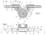
- a tubular portion 7 that accepts a rotator mechanism and has an open end 8 and an internal closed end (shown particularly in Figure 3 ).
- Each arm 5 also includes a channel 10 that presents an aperture in the outer surface of the arm 5 and extends to the closed end of the tubular portion 7 of the arm 5. Channel 10 is dimensioned to house a ball 11, a compression spring 12 and a grub screw 13.
- the rotator mechanism comprises a cylindrical rotator arm 20 with a retaining flange 21 midway along its length, a cylindrical open-ended bearing sleeve 22 and a projecting tab 23.
- the bearing sleeve 22 is dimensioned to fit snugly within the tubular portion 7 of the arm 5 and has a retaining flange 24 at its outer end to prevent the sleeve 22 moving too far inside the arm 5. In use, the sleeve 22 acts as a bush between the arm 5 and the rotator arm 20.
- Rotator arm 20 has a frame-connecting portion 20a and an arm-connecting portion 20b, separated by the retaining flange 21.
- Frame-connecting portion 20a is dimensioned to fit within a tubular bed frame and includes opposing holes 25 which accept screws, rivets or pins (not shown) that allow attachment of the entire hinge 1 to the bed frame.
- the projecting metal tab 23 is the visible end of a metal reinforcing component that is moulded within the rotator arm 20.
- the tab 23 projects in order to allow the metal insert to be held while a polymer is injected into a mould surrounding it. Holes shown in the drawings in the portion 20b of the rotator arm are created by retractable pins used to support the metal insert during the moulding process and do not serve any specific purpose.
- Each arm-connecting portion 20b has a smaller circumference than frame-connecting portion 20a and is dimensioned to fit within sleeve 22.
- Each arm-connecting portion 20b has a length that corresponds to the length of the tubular end 7 of arm 5 (shown in Figure 3 ) and its free end has two recesses 28 located opposite each other on the circumference and a circumferential groove 26, which accepts a retaining pin 27.
- the thread mechanism comprises a central thread 30 and an outer thread assembly 31.
- the central thread 30 has a hexagonal central hole and the rear cap 3 is fixed to the central thread 30 by a corresponding hexagonal spigot 32 located on the inner surface of the cap 3.
- a metal washer 34 and self-tapping screw 35 that locates into a moulding 36 in the centre of spigot 32 holds the central thread 30 captive such that it rotates with a handle or knob 33.
- the head of the screw 35 is covered by a cap 37.
- Outer thread assembly 31 has a tubular core 38, with a thread 39 lining the inner surface, and a screw mounting 40.
- the thread 39 has a pitch that corresponds to the pitch of the central thread 30.
- the screw mounting 40 allows fixing of the outer thread assembly 31 to the wheel 2b by way of screws 41.
- Flanges 42 depend from the under surface of the screw mounting 40 and assist with location of the outer thread assembly 31 by locating within slots moulded on the inside of wheel 2b. The flanges 42 also add to the restriction of rotational movement of the outer thread assembly 31 with respect to wheel 2b when the hinge 1 is in use.
- Assembly of the hinge 1 is shown in cross section in Figure 3 .
- the thread mechanism is located through the centre of the ratcheted wheels 2; the central thread 30 fits snugly over hexagonal spigot 32 and carries the outer thread assembly 31 on its thread.
- the rotator mechanism is located inside the tubular portion 7 of each arm 5.
- Sleeve 22 is positioned inside tubular portion 7 until its flange 24 abuts the open end 8 of the arm 5.
- Rotator arm 20 is inserted inside the sleeve until its flange 21 abuts sleeve flange 24.
- the retaining pin 27 is located in the retaining pin groove 26 to hold the rotator arm 20 within the tubular portion 7 of the arm 5.
- a ball 11 serving as a detent is inserted into channel 10 and a compression spring 12 is inserted behind the ball 11, the spring 12 being held in place by a grub screw 13.
- the ball serves as a latch and offers resistance to rotation of the rotator arm 20 when the ball 11 sits within one of the two recesses 28.
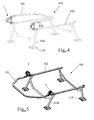
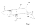
- Figures 4 to 6 illustrate use of the hinge 1 in a bedchair frame.
- a bedchair has a folding frame formed of three mutually pivotable sections that are selectively lockable relative to one another.
- the frame can adopt a compact configuration for transportation in which the three sections lie generally parallel to one another.
- the sections lie generally in the same plane as one another while, in a chair configuration, a leg support section is dropped and the back support section is raised.
- Only the back and seat frames are shown in Figures 4 to 6 .
- the bedchair is conventional and for this reason it is not believed necessary to describe it in greater detail.
- the frame 100 is in a folded configuration with the back section 101 being folded over the seat section 102.
- the two sections are linked together by hinge 1 which is fixed to the frame 100 by screws or rivets 103.
- Back section 101 does not fold directly onto the seat section 102 due to the depth of the hinge 1, thereby allowing space for integral or detachable bedding, such as a mattress and/or a sleeping bag or quilt.
- Legs 104 depend from seat section 102 and include feet 105.
- the offset hinge 1 is in a vertical orientation above of the plane of the bed, providing an obstacle when getting in and out of bed and discomfort when in the bed.
- the rotator mechanism allows the hinge 1 to be rotated out of the plane of the frame 100 (see Figure 6 ).
- hand pressure is applied to the side of hinge 1 to guide it in its rotation.
- the pressure causes ball 11 to move out of the recess 28 and allows rotation of rotator arm 20.
- the rotator arm 20 will rotate freely until pressure from the compression spring 12 forces the ball bearing 11 into the other recess 28, at which point the hinge 1 is locked into a new position.
- the hinge 1 can be locked either vertically above the plane of the frame 100, or vertically below the plane of the frame 100.
Landscapes
- Health & Medical Sciences (AREA)
- General Health & Medical Sciences (AREA)
- Nursing (AREA)
- Dentistry (AREA)
- Pivots And Pivotal Connections (AREA)
Applications Claiming Priority (1)
| Application Number | Priority Date | Filing Date | Title |
|---|---|---|---|
| GB1013369.2A GB2482684A (en) | 2010-08-09 | 2010-08-09 | Hinge mechanism for folding bed |
Publications (1)
| Publication Number | Publication Date |
|---|---|
| EP2417874A1 true EP2417874A1 (fr) | 2012-02-15 |
Family
ID=42931395
Family Applications (1)
| Application Number | Title | Priority Date | Filing Date |
|---|---|---|---|
| EP11175783A Withdrawn EP2417874A1 (fr) | 2010-08-09 | 2011-07-28 | Charnière pour chaise-lit pliable |
Country Status (2)
| Country | Link |
|---|---|
| EP (1) | EP2417874A1 (fr) |
| GB (1) | GB2482684A (fr) |
Families Citing this family (1)
| Publication number | Priority date | Publication date | Assignee | Title |
|---|---|---|---|---|
| CN105443567B (zh) * | 2015-11-27 | 2018-01-12 | 平湖市陈达仓储办公设备有限公司 | 一种电动床的床板连接结构 |
Citations (1)
| Publication number | Priority date | Publication date | Assignee | Title |
|---|---|---|---|---|
| EP2374375A1 (fr) * | 2010-02-22 | 2011-10-12 | Fox International Group Limited | Chaise-lit |
Family Cites Families (3)
| Publication number | Priority date | Publication date | Assignee | Title |
|---|---|---|---|---|
| GB2344510A (en) * | 1998-12-03 | 2000-06-14 | Fox Design Int | Bed-chair or other support means |
| GB2428966B (en) * | 2005-08-12 | 2007-09-05 | Trakker Products Ltd | Improvements to seats, bed chairs and the like |
| US7537187B2 (en) * | 2005-11-03 | 2009-05-26 | Frederick K. Park | Collapsible frame structures |
-
2010
- 2010-08-09 GB GB1013369.2A patent/GB2482684A/en not_active Withdrawn
-
2011
- 2011-07-28 EP EP11175783A patent/EP2417874A1/fr not_active Withdrawn
Patent Citations (1)
| Publication number | Priority date | Publication date | Assignee | Title |
|---|---|---|---|---|
| EP2374375A1 (fr) * | 2010-02-22 | 2011-10-12 | Fox International Group Limited | Chaise-lit |
Also Published As
| Publication number | Publication date |
|---|---|
| GB2482684A (en) | 2012-02-15 |
| GB201013369D0 (en) | 2010-09-22 |
Similar Documents
| Publication | Publication Date | Title |
|---|---|---|
| US11465010B2 (en) | Foldable exercise bench | |
| US10959525B2 (en) | Collapsible swivel chair | |
| US8113396B2 (en) | Chair and pack frame combination | |
| US7549398B2 (en) | Adjustable wheelchair for pets | |
| US7325875B1 (en) | Beach chair | |
| US5522644A (en) | Variably adjustable lower body support for wheel chair | |
| US8128103B1 (en) | Deployable side seat for a baby stroller | |
| US11330893B2 (en) | Adjustable footprint suspension seat frame system | |
| US20090174233A1 (en) | Washer cap and rotating stool | |
| US6533237B1 (en) | Apparatus and method for holding an elongated member | |
| US20140183831A1 (en) | Walking aid device with foldable seat | |
| US20100172690A1 (en) | Adjustable connector for tubular frames | |
| US5988750A (en) | Substantially non-freestanding backrest | |
| US12604983B2 (en) | Collapsible chair | |
| US8702162B2 (en) | Multiple use chair | |
| US10196113B2 (en) | Multi-position user support device for a stand-up paddle board | |
| US10668992B2 (en) | Multi-position user support device for a stand-up paddle board | |
| GB2482684A (en) | Hinge mechanism for folding bed | |
| EP1694165A1 (fr) | Ameliorations apportees aux sieges escamotables et en rapport avec ceux-ci | |
| KR101296357B1 (ko) | 의자등받이 | |
| EP3759044A1 (fr) | Système de selle | |
| EP2374375B1 (fr) | Chaise-lit | |
| US5769767A (en) | Exercise device | |
| GB2114880A (en) | Footrest | |
| US7028641B1 (en) | Spring-loaded animal tether assembly |
Legal Events
| Date | Code | Title | Description |
|---|---|---|---|
| AK | Designated contracting states |
Kind code of ref document: A1 Designated state(s): AL AT BE BG CH CY CZ DE DK EE ES FI FR GB GR HR HU IE IS IT LI LT LU LV MC MK MT NL NO PL PT RO RS SE SI SK SM TR |
|
| AX | Request for extension of the european patent |
Extension state: BA ME |
|
| PUAI | Public reference made under article 153(3) epc to a published international application that has entered the european phase |
Free format text: ORIGINAL CODE: 0009012 |
|
| 111L | Licence recorded |
Designated state(s): AL AT BE BG CH CY CZ DE DK EE ES FI FR GB GR HR HU IE IS IT LT LU LV MC MK MT NL NO PL PT RO RS SE SI SK SM TR Name of requester: KEVIN NASH GROUP, GB Effective date: 20120215 |
|
| STAA | Information on the status of an ep patent application or granted ep patent |
Free format text: STATUS: THE APPLICATION IS DEEMED TO BE WITHDRAWN |
|
| 18D | Application deemed to be withdrawn |
Effective date: 20120817 |