EP2418322B1 - Caniveau de drainage - Google Patents
Caniveau de drainage Download PDFInfo
- Publication number
- EP2418322B1 EP2418322B1 EP10013406.3A EP10013406A EP2418322B1 EP 2418322 B1 EP2418322 B1 EP 2418322B1 EP 10013406 A EP10013406 A EP 10013406A EP 2418322 B1 EP2418322 B1 EP 2418322B1
- Authority
- EP
- European Patent Office
- Prior art keywords
- tube
- face wall
- tunnel
- rail
- drainage channel
- Prior art date
- Legal status (The legal status is an assumption and is not a legal conclusion. Google has not performed a legal analysis and makes no representation as to the accuracy of the status listed.)
- Not-in-force
Links
- 239000011324 bead Substances 0.000 claims description 4
- 239000002352 surface water Substances 0.000 description 6
- XLYOFNOQVPJJNP-UHFFFAOYSA-N water Substances O XLYOFNOQVPJJNP-UHFFFAOYSA-N 0.000 description 6
- 239000000463 material Substances 0.000 description 5
- 238000007789 sealing Methods 0.000 description 4
- 239000002131 composite material Substances 0.000 description 2
- 238000003780 insertion Methods 0.000 description 2
- 230000037431 insertion Effects 0.000 description 2
- 238000009434 installation Methods 0.000 description 2
- 239000010865 sewage Substances 0.000 description 2
- 238000005452 bending Methods 0.000 description 1
- 230000000295 complement effect Effects 0.000 description 1
- 238000010276 construction Methods 0.000 description 1
- 230000001419 dependent effect Effects 0.000 description 1
- 238000006073 displacement reaction Methods 0.000 description 1
- 230000002452 interceptive effect Effects 0.000 description 1
- 238000000926 separation method Methods 0.000 description 1
- 239000011343 solid material Substances 0.000 description 1
- 230000005641 tunneling Effects 0.000 description 1
Images



Classifications
-
- E—FIXED CONSTRUCTIONS
- E01—CONSTRUCTION OF ROADS, RAILWAYS, OR BRIDGES
- E01B—PERMANENT WAY; PERMANENT-WAY TOOLS; MACHINES FOR MAKING RAILWAYS OF ALL KINDS
- E01B21/00—Track superstructure adapted for tramways in paved streets
- E01B21/02—Special supporting means; Draining of rails
Definitions
- the present invention relates to a drainage channel for drainage of rails, in particular tram rails, comprising a channel body with an end wall, which is associated with an inlet opening for draining a arranged in the rail head of the rail rail groove via an inlet funnel, wherein the inlet funnel is associated with a front panel, which, forming part of the end wall, inserted into a receptacle associated with the end wall in the horizontal direction, can be.
- Such a drainage channel is already out of the DE 20 2006 008 831 U1 previously known.
- assign the inlet funnel of the end wall forming plate characterized in that the inlet funnel is inserted through an inlet opening and locked in a stop position.
- the rail groove drainage openings which are provided at certain intervals.
- the rails are crossed by drainage channels, into which the drainage openings of the rails open.
- the abovementioned, previously known solution provides for a beak-shaped inlet funnel, which is pushed from inside to the underside of the rail by means of a rail to the end wall of the drainage channel and fastened there.
- either a drain pipe opening into the sewage system can be provided, or else the gutter line can be continued.
- the water guided by the drainage channel can pass under the rail.
- a tunnel tube is provided, which connect the drainage channels or the drainage channel and the drainage pipe to each other below the rail from both sides.
- the present invention is intended to show an alternative to push-through drainage tubes.
- the inlet through the drainage opening of the rail into the gutter body usually takes place via an inlet opening of the end wall, which is assigned an inlet funnel.
- the solution according to the invention in the region of the end wall on a front panel, to which an inlet funnel is attached.
- a front panel is inserted into a receptacle of the end wall, which passes transversely through the end wall in the direction parallel to the rail.
- the inlet funnel is therefore to be fastened to the front wall from outside the inside of the channel.
- this is a rectangular receptacle, so that the front panel can be inserted from both sides into the receptacle. Therefore, not the end wall as such has the inlet opening, but rather the front panel, through which the water flowing in via the drainage opening of the rail passes through the inlet funnel into the channel.
- the inlet opening is provided in the end wall.
- the invention provides in this case that the inlet funnel is made in two parts, with two funnel halves are pushed towards each other in the direction parallel to the rails and meet in a central stop position where they unite to form a common inlet funnel.
- the inlet funnel engages under the drainage opening of the rail and connects it to the end wall in such a way that the water to be drained from the drainage opening into the inlet funnel can enter the gutter body through the end wall and its inlet opening.
- the inlet funnel is in this case preferably formed of two different materials, namely substantially of a rigid, dimensionally stable material and in the region of the rail under cross-leading edge of a soft, adapting to the position of the rail material.
- the two funnel halves are each provided with one, preferably two or more, guide elements which are each accommodated in a rail guide flanking the inlet opening on one or both sides.
- a rail guide allows the exact positioning of the inlet funnel in front of the inlet opening of the end wall, so that the two halves of the inlet funnel connect in their stop positions to the common inlet funnel.
- a sealing lip is arranged in an advantageous embodiment, so that water entering via the inlet funnel does not seep down at the abutting edge of the two funnel halves.
- the rail guides in the region of their stop position on a latch, in which engage the guide elements of the hopper halves, as soon as they are moved to the stop position.
- a further development of the aforementioned drainage channel has in the region of a tunnel opening provided in its end wall a projection on which a tunnel tube can be slid from the outside. Such, pushed out from the outside tunnel tube has the advantage that a subsequent displacement of the tunnel tube, by whatever circumstances, is excluded.
- the tunnel tube can be easily positioned from the outside and continue in the other the installation either as a drain pipe or as an extended drainage channel.
- the tunnel tube in two parts, ideally two identical parts are used.
- the two, preferably identical, tube halves are connected together along their longitudinal edges, wherein locking means and corresponding counter-locking means are provided in particular along these longitudinal edges.
- the locking means engage in the counter-locking means in such a way that, at least when placed on the projection of the end wall, a secure mounting of the thus assembled tunnel tube is ensured.
- the tube halves may, in a concrete embodiment along a longitudinal edge having a tab which engages over a portion of the respective opposite longitudinal edge of the respective other tube half.
- locking means and counter-locking means can then be arranged.
- a locking means or counter-locking means are particularly preferably a bead and a hierein engaging bulge to provide, which at least largely positively and / or non-positively engage with each other.
- any other locking means and counter-locking means are also used.
- a tube half can be slipped from one side onto the projection, after which the other tube half is pushed over the projection from the other side. In the successive meeting of the two tube halves then snap the locking means in the counter-locking means and connect the tube halves to a common tunnel tube.
- a drain pipe is provided on the opposite side of the channel, so opposite the considered drainage channel, so this also has an end wall with a projection which protrudes away from the drain pipe, ie under the rail.
- this projection encloses on the outside, or engages the tunnel tube in said projection.
- a stop for the tunnel tube may be provided within the projection, so that it is held in place.
- a second drainage channel may be arranged on the other side of the rail, which is constructed substantially identical to the first.
- the second drainage channel can also, like the end wall of the drainage tube, have a projection which engages around the tunnel tube on the outside, instead of interfering therewith.
- a facing or a non-penetrated end wall must be provided, since, as already explained above, a drainage opening of the rail is only present on one side.
- an inlet into this second drainage channel at best by the tunnel tube, but not done by an inlet funnel or an inlet opening in the front wall.
- the channel element can either be connected directly to an end wall, ie the end wall can be made in one piece with the channel element.
- the end wall can be put directly on the gutter body, in particular to connect this with the end wall, for example with the interposition of a seal.
- the end wall is associated with a short, separate channel section, which can be connected as an end piece in the usual way with the drainage channel.
- FIG. 1 shows a drainage channel in an exploded view.
- the drainage channel consists of a channel body 10 which is closed on both sides by end elements 11.
- the end elements 11 are configured such that they are designed to drain a railroad track then to drain.
- the end elements 11 inlet openings 15 through which collected in the tram rail surface water can enter the drainage channel.
- To undercut the rails additionally has the end member 11 a tunnel opening 13, which is surrounded by a projection 14. In this way, introduced into the drainage channel surface water can be introduced from the channel body 10 out into the sewage system or on the other side of the tram track continued drainage channels are derived.
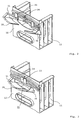
- FIG. 2 shows as a detail of such a drainage channel a front element 11, which has an inlet funnel 30 for introducing the surface water originating from the rail 40 into the channel body 10.
- This inlet funnel is formed in two parts in the embodiment shown, namely from a first funnel half 31 and a second funnel half 32, which are moved towards each other from both sides of an inlet opening via a rail guide 34.
- the first funnel half 31 and the second funnel half 32 each have guide elements 33 which engage in the rail guide 34.
- FIG. 3 shows the two funnel halves 31, 32 in their stop position.
- the first funnel half 31 and the second funnel half 32 complement each other to form a common inlet funnel 30, wherein a sealing element 35 in the form of a sealing lip is arranged along the abutting edge.
- a locking is also provided, which prevents a disengagement of the funnel halves 31 and 32.
- FIG. 4 shows an alternative embodiment of the inlet funnel 30, which is connected in this case with a front panel 36. Together with the front panel 36 of this feed hopper 30 is inserted into a receptacle 16 of the end wall 12.
- the receptacle 16 in this case represents the end wall 12 transversely by cross-rectangle, which can be completely filled by the front panel 36.
- a guide rail is provided, in which the front panel 36, preferably sealing, can engage.
- FIG. 5 shows the front panel 36 in its fully inserted position.
- a lateral insertion is possible parallel to the course of the adjacent rail 40, while the feed hopper 30 in this case remains permanently in contact with the rail head 41 in the region of the rail groove 42.
- the inlet funnel 30 engages under the drainage opening 43 within the rail groove 42, so that the surface water standing in the rail groove can enter via the drainage opening 43 and the inlet opening 15 into the drainage channel.
- the inlet funnel consists of a two-part material, namely in the region of the funnel of a stiff, solid material and in the region of its leading edge, which comes into contact with the rail head 41, from a soft, adaptable in its shape material.
- the rail 40 is underrun by a tunnel tube 20, which is connected in the region of the projection 14 with the end wall 12 of the drainage channel.
- FIG. 6 shows such a tunnel tube 20, which is composed of a first tube half 21 and a second tube half 22.
- a tunnel tube 20 which is composed of a first tube half 21 and a second tube half 22.
- each of the two tube halves 21, 22 along a longitudinal edge 23 has a bead 25 into which a flap 24 associated bulge 26 can engage.
- both tube halves 21, 22 form a tunnel tube 20, which configuration is inherently unstable. By a simple lifting transverse to the longitudinal axis this can be separated again.
- FIG. 8 This is prevented as in FIG. 8 is shown.
- the composite tunnel tube 20 is pushed onto the projection 14 of the end wall 12, which thereby prevents an upward or longitudinal deflection. This results in the tunnel tube 20 in its installed state, a stable construction, which has no disadvantages over a one-piece tunnel tube 20.
- FIG. 8 is from the drainage channel opposite side an end wall 18 of a drain pipe used for the other side boundary of the tunnel tube 20, so that the drainage channel can derive the guided in her water, which enters from the rail groove 42 via the drainage opening 43 into the gutter body 10, directly into the sewer.
- FIG. 9 An appropriate compilation is in FIG. 9 shown, it can be seen through the lateral plan view that the end wall 18 of the drain pipe has a projection 19 which does not engage in the tunnel tube 20, but rather this engages on the outside. A removal of the tunnel tube 20 without a prior removal of the end wall 18 of the drain pipe is thus prevented.
- FIG. 3 shows a configuration according to which a continuation of the drainage channel beyond the rail 40 is possible.
- the drainage channels are laid on both sides of the rails 40, such that the end elements 11 have mutually opposite projections 14.
- the tunnel tube 20 is then composed from both sides of the two tube halves 21, 22 by first the first tube half 21 is pushed over the projection 14 and then from the other side, the second tube half 22 is pushed over it.
- the bulge present in the respective lug lying over the longitudinal edge locks with the bead running along the longitudinal edge, so that after positioning the tube halves 21, 22 a separation is only possible against bending of the latches.
Landscapes
- Engineering & Computer Science (AREA)
- Architecture (AREA)
- Civil Engineering (AREA)
- Structural Engineering (AREA)
- Lining And Supports For Tunnels (AREA)
- Retaining Walls (AREA)
Claims (8)
- Caniveau de drainage pour le drainage de rails, en particulier de rails de tramway, comprenant un entonnoir d'entrée (30) et un corps de caniveau (10) avec une paroi d'extrémité frontale (12) à laquelle est associée une ouverture d'entrée (15) pour le drainage d'une rainure de rail (42) disposée dans le champignon de rail (41) du rail (40) via l'entonnoir d'entrée (30), dans laquelle l'entonnoir d'entrée (30) est associé à un volet frontal (36) qui fait partie de la paroi d'extrémité frontale (12) et qui peut être inséré dans le sens horizontal dans un réceptacle (16) associé à la paroi d'extrémité frontale (12), caractérisée en ce que le réceptacle (16) s'étend à travers la paroi d'extrémité frontale perpendiculairement au corps de caniveau.
- Caniveau de drainage selon la revendication 1, caractérisé en ce que la paroi d'extrémité frontale (12) est associée, via une ouverture de tunnel (13), à un tuyau de forme tunnel (20) traversant sous le rail (40), l'ouverture de tunnel (13) présentant sur le côté extérieur du caniveau un collet (14) sur lequel le tuyau de forme tunnel (13) peut être emboîté à partir de l'extérieur du caniveau.
- Caniveau de drainage selon la revendication 2, caractérisé en ce que le tuyau de forme tunnel (20) se compose de deux moitiés de tuyau (21, 22) pouvant être enfoncées par les deux côtés par-dessus le collet (14) de la paroi d'extrémité frontale (12), qui sont reliées entre elles à cet endroit le long de leurs bords longitudinaux (23).
- Caniveau de drainage selon l'une des revendications 2 ou 3, caractérisé en ce que le tuyau de forme tunnel (20) est formé de deux moitiés de tuyau (21, 22) identiques qui présentent de part et d'autre le long de leurs bords longitudinaux (23) des moyens d'encliquetage ou de verrouillage et des moyens d'encliquetage ou de verrouillage opposés pour un encliquetage ou un verrouillage mutuel des moitiés de tuyau (21, 22).
- Caniveau de drainage selon la revendication 4, caractérisé en ce que chaque moitié de tuyau (21, 22) forme une patte (24) passant par-dessus le bord longitudinal (23) de l'autre moitié de tuyau (22, 21) et présentant un bombement (26) qui se met en prise dans une moulure (25) parallèle au bord longitudinal (23).
- Caniveau de drainage selon l'une des revendications 2 à 5, caractérisé en ce que se raccorde au-delà du tuyau de forme tunnel (20), vu depuis la paroi d'extrémité frontale (12), une paroi d'extrémité frontale (18) reliée à un tuyau d'évacuation (17), qui présente un collet (19) orienté vers le tuyau de forme tunnel (20) qui entoure le tuyau de forme tunnel (20) ou pénètre dans celui-ci.
- Caniveau de drainage selon l'une des revendications 2 à 5, caractérisé en ce que se raccorde au-delà du tuyau de forme tunnel (20), vu depuis la paroi d'extrémité frontale (12), un autre corps de caniveau (10) qui présente une paroi d'extrémité frontale dans laquelle soit aucune ouverture d'entrée n'est prévue, soit une ouverture d'entrée est fermée par un volet.
- Caniveau de drainage selon l'une des revendications précédentes, caractérisé en ce que la paroi d'extrémité frontale (12) soit est directement assemblée au corps de caniveau (10), soit peut lui être directement assemblée, soit est reliée à un élément frontal (11) reproduisant la forme du caniveau et pouvant être assemblé à celle-ci.
Applications Claiming Priority (1)
| Application Number | Priority Date | Filing Date | Title |
|---|---|---|---|
| DE201020008256 DE202010008256U1 (de) | 2010-08-10 | 2010-08-10 | Entwässerungsrinne |
Publications (3)
| Publication Number | Publication Date |
|---|---|
| EP2418322A2 EP2418322A2 (fr) | 2012-02-15 |
| EP2418322A3 EP2418322A3 (fr) | 2014-05-07 |
| EP2418322B1 true EP2418322B1 (fr) | 2016-04-27 |
Family
ID=43049673
Family Applications (1)
| Application Number | Title | Priority Date | Filing Date |
|---|---|---|---|
| EP10013406.3A Not-in-force EP2418322B1 (fr) | 2010-08-10 | 2010-10-07 | Caniveau de drainage |
Country Status (2)
| Country | Link |
|---|---|
| EP (1) | EP2418322B1 (fr) |
| DE (1) | DE202010008256U1 (fr) |
Families Citing this family (8)
| Publication number | Priority date | Publication date | Assignee | Title |
|---|---|---|---|---|
| DE102011013721A1 (de) * | 2011-03-11 | 2012-09-13 | Mea Bausysteme Gmbh | Schienensystem mit einer Entwässerung |
| FR2978777B1 (fr) | 2011-08-04 | 2013-09-06 | Aco Produits Polymeres | Caniveau pour voie ferree de tramway |
| CN103061211A (zh) * | 2013-01-11 | 2013-04-24 | 米亚建筑材料(昆山)有限公司 | 轨道间排水箱 |
| DE102013206602A1 (de) * | 2013-04-12 | 2014-10-30 | Mea Bausysteme Gmbh | Entwässerungssystem für eine Schiene |
| CN112095371A (zh) * | 2020-09-11 | 2020-12-18 | 中国建筑第八工程局有限公司 | 用于槽型轨的雨水收集排水装置 |
| CN113833523B (zh) * | 2021-08-31 | 2026-05-01 | 山东大学 | 一种适用于富水软岩地层隧道台阶开挖的排水装置及方法 |
| CN113892471B (zh) * | 2021-09-03 | 2022-09-09 | 皖西学院 | 一种智能农业机器人及其使用方法 |
| CN115467706B (zh) * | 2022-08-31 | 2024-05-07 | 中铁第一勘察设计院集团有限公司 | 隧道水量平衡系统 |
Family Cites Families (3)
| Publication number | Priority date | Publication date | Assignee | Title |
|---|---|---|---|---|
| FR2765599B1 (fr) | 1997-07-01 | 2003-06-13 | Aco Produits Polymeres | Systeme de drainage pour voies ferrees de tramway |
| DE20005074U1 (de) * | 2000-03-20 | 2000-06-29 | Hauraton Betonwarenfabrik GmbH & Co KG, 76437 Rastatt | Schienenentwässerungssystem |
| DE202006008831U1 (de) * | 2006-06-03 | 2006-08-17 | Hauraton Gmbh & Co. Kg | Entwässerungsvorrichtung |
-
2010
- 2010-08-10 DE DE201020008256 patent/DE202010008256U1/de not_active Expired - Lifetime
- 2010-10-07 EP EP10013406.3A patent/EP2418322B1/fr not_active Not-in-force
Also Published As
| Publication number | Publication date |
|---|---|
| EP2418322A2 (fr) | 2012-02-15 |
| DE202010008256U1 (de) | 2010-11-04 |
| EP2418322A3 (fr) | 2014-05-07 |
Similar Documents
| Publication | Publication Date | Title |
|---|---|---|
| EP2418322A2 (fr) | Caniveau de drainage | |
| WO2012016636A2 (fr) | Profilé d'armoire, en particulier profilé d'armoire de distribution et armoire, en particulier armoire de distribution | |
| DE102007017100A1 (de) | Verbindungselement und Schutzabdeckung | |
| DE3045675A1 (de) | Abschluss- und dichtstreifen | |
| EP2899325B1 (fr) | Système d'étanchéification | |
| DE202017105927U1 (de) | Führungseinrichtung | |
| EP2826652B1 (fr) | Cadre d'un toit coulissant de véhicule avec caniveaux de câbles | |
| DE29924372U1 (de) | Einführungsplatte für Rohrsysteme | |
| DE202004005987U1 (de) | Kabelkanalsystem | |
| EP1780345B1 (fr) | Raccord pour profilés en forme de U et ensemble de raccordement | |
| EP0790360A1 (fr) | Caniveau d'écoulement | |
| EP1488885B1 (fr) | Tablier de protection, en particulier pour machines-outils | |
| DE102010047991A1 (de) | Befestigungssystem eines Kabelübergangsgerätes in einem Mast | |
| DE19620978A1 (de) | Entwässerungsrinne | |
| DE202018105805U1 (de) | Beschlagteil | |
| DE102008018113A1 (de) | Fahrzeugrückhaltesystem | |
| DE69613744T2 (de) | Schutzvorrichtung zum Verhindern des Eindringens von Wasser in eine Wand und zum Verbessern des Abführens von Wasser aus einer Wand | |
| EP3420149B1 (fr) | Élément de raccordement entre une canalisation et une bouche d'égout | |
| DE202004018370U1 (de) | Kontrollschacht für ein Wasserleitsystem | |
| DE9320134U1 (de) | Injizierbare Fugenschiene | |
| EP0908568B1 (fr) | Dispositif de verrouillage pour des grilles dans des cadres | |
| EP1399627A1 (fr) | Corps de canal de drainage, constitue en particulier de beton polymere | |
| DE102008051440B4 (de) | Paneelelement | |
| DE102019003941B4 (de) | Durchführung zum Einbau in ein Wand- oder Bodenelement | |
| DE102024102333A1 (de) | Fassadenrinne |
Legal Events
| Date | Code | Title | Description |
|---|---|---|---|
| AK | Designated contracting states |
Kind code of ref document: A2 Designated state(s): AL AT BE BG CH CY CZ DE DK EE ES FI FR GB GR HR HU IE IS IT LI LT LU LV MC MK MT NL NO PL PT RO RS SE SI SK SM TR |
|
| AX | Request for extension of the european patent |
Extension state: BA ME |
|
| PUAI | Public reference made under article 153(3) epc to a published international application that has entered the european phase |
Free format text: ORIGINAL CODE: 0009012 |
|
| PUAL | Search report despatched |
Free format text: ORIGINAL CODE: 0009013 |
|
| AK | Designated contracting states |
Kind code of ref document: A3 Designated state(s): AL AT BE BG CH CY CZ DE DK EE ES FI FR GB GR HR HU IE IS IT LI LT LU LV MC MK MT NL NO PL PT RO RS SE SI SK SM TR |
|
| AX | Request for extension of the european patent |
Extension state: BA ME |
|
| RIC1 | Information provided on ipc code assigned before grant |
Ipc: E01B 21/02 20060101AFI20140403BHEP |
|
| 17P | Request for examination filed |
Effective date: 20140614 |
|
| RBV | Designated contracting states (corrected) |
Designated state(s): AL AT BE BG CH CY CZ DE DK EE ES FI FR GB GR HR HU IE IS IT LI LT LU LV MC MK MT NL NO PL PT RO RS SE SI SK SM TR |
|
| GRAP | Despatch of communication of intention to grant a patent |
Free format text: ORIGINAL CODE: EPIDOSNIGR1 |
|
| INTG | Intention to grant announced |
Effective date: 20151102 |
|
| GRAS | Grant fee paid |
Free format text: ORIGINAL CODE: EPIDOSNIGR3 |
|
| GRAA | (expected) grant |
Free format text: ORIGINAL CODE: 0009210 |
|
| AK | Designated contracting states |
Kind code of ref document: B1 Designated state(s): AL AT BE BG CH CY CZ DE DK EE ES FI FR GB GR HR HU IE IS IT LI LT LU LV MC MK MT NL NO PL PT RO RS SE SI SK SM TR |
|
| REG | Reference to a national code |
Ref country code: GB Ref legal event code: FG4D Free format text: NOT ENGLISH |
|
| REG | Reference to a national code |
Ref country code: CH Ref legal event code: EP |
|
| REG | Reference to a national code |
Ref country code: AT Ref legal event code: REF Ref document number: 794964 Country of ref document: AT Kind code of ref document: T Effective date: 20160515 |
|
| REG | Reference to a national code |
Ref country code: IE Ref legal event code: FG4D Free format text: LANGUAGE OF EP DOCUMENT: GERMAN |
|
| REG | Reference to a national code |
Ref country code: DE Ref legal event code: R096 Ref document number: 502010011539 Country of ref document: DE |
|
| REG | Reference to a national code |
Ref country code: LT Ref legal event code: MG4D |
|
| REG | Reference to a national code |
Ref country code: NL Ref legal event code: MP Effective date: 20160427 |
|
| PG25 | Lapsed in a contracting state [announced via postgrant information from national office to epo] |
Ref country code: NL Free format text: LAPSE BECAUSE OF FAILURE TO SUBMIT A TRANSLATION OF THE DESCRIPTION OR TO PAY THE FEE WITHIN THE PRESCRIBED TIME-LIMIT Effective date: 20160427 |
|
| REG | Reference to a national code |
Ref country code: FR Ref legal event code: PLFP Year of fee payment: 7 |
|
| PG25 | Lapsed in a contracting state [announced via postgrant information from national office to epo] |
Ref country code: NO Free format text: LAPSE BECAUSE OF FAILURE TO SUBMIT A TRANSLATION OF THE DESCRIPTION OR TO PAY THE FEE WITHIN THE PRESCRIBED TIME-LIMIT Effective date: 20160727 Ref country code: LT Free format text: LAPSE BECAUSE OF FAILURE TO SUBMIT A TRANSLATION OF THE DESCRIPTION OR TO PAY THE FEE WITHIN THE PRESCRIBED TIME-LIMIT Effective date: 20160427 Ref country code: FI Free format text: LAPSE BECAUSE OF FAILURE TO SUBMIT A TRANSLATION OF THE DESCRIPTION OR TO PAY THE FEE WITHIN THE PRESCRIBED TIME-LIMIT Effective date: 20160427 Ref country code: PL Free format text: LAPSE BECAUSE OF FAILURE TO SUBMIT A TRANSLATION OF THE DESCRIPTION OR TO PAY THE FEE WITHIN THE PRESCRIBED TIME-LIMIT Effective date: 20160427 |
|
| PG25 | Lapsed in a contracting state [announced via postgrant information from national office to epo] |
Ref country code: PT Free format text: LAPSE BECAUSE OF FAILURE TO SUBMIT A TRANSLATION OF THE DESCRIPTION OR TO PAY THE FEE WITHIN THE PRESCRIBED TIME-LIMIT Effective date: 20160829 Ref country code: ES Free format text: LAPSE BECAUSE OF FAILURE TO SUBMIT A TRANSLATION OF THE DESCRIPTION OR TO PAY THE FEE WITHIN THE PRESCRIBED TIME-LIMIT Effective date: 20160427 Ref country code: RS Free format text: LAPSE BECAUSE OF FAILURE TO SUBMIT A TRANSLATION OF THE DESCRIPTION OR TO PAY THE FEE WITHIN THE PRESCRIBED TIME-LIMIT Effective date: 20160427 Ref country code: GR Free format text: LAPSE BECAUSE OF FAILURE TO SUBMIT A TRANSLATION OF THE DESCRIPTION OR TO PAY THE FEE WITHIN THE PRESCRIBED TIME-LIMIT Effective date: 20160728 Ref country code: LV Free format text: LAPSE BECAUSE OF FAILURE TO SUBMIT A TRANSLATION OF THE DESCRIPTION OR TO PAY THE FEE WITHIN THE PRESCRIBED TIME-LIMIT Effective date: 20160427 Ref country code: SE Free format text: LAPSE BECAUSE OF FAILURE TO SUBMIT A TRANSLATION OF THE DESCRIPTION OR TO PAY THE FEE WITHIN THE PRESCRIBED TIME-LIMIT Effective date: 20160427 Ref country code: HR Free format text: LAPSE BECAUSE OF FAILURE TO SUBMIT A TRANSLATION OF THE DESCRIPTION OR TO PAY THE FEE WITHIN THE PRESCRIBED TIME-LIMIT Effective date: 20160427 |
|
| PG25 | Lapsed in a contracting state [announced via postgrant information from national office to epo] |
Ref country code: IT Free format text: LAPSE BECAUSE OF FAILURE TO SUBMIT A TRANSLATION OF THE DESCRIPTION OR TO PAY THE FEE WITHIN THE PRESCRIBED TIME-LIMIT Effective date: 20160427 |
|
| REG | Reference to a national code |
Ref country code: DE Ref legal event code: R097 Ref document number: 502010011539 Country of ref document: DE |
|
| PG25 | Lapsed in a contracting state [announced via postgrant information from national office to epo] |
Ref country code: EE Free format text: LAPSE BECAUSE OF FAILURE TO SUBMIT A TRANSLATION OF THE DESCRIPTION OR TO PAY THE FEE WITHIN THE PRESCRIBED TIME-LIMIT Effective date: 20160427 Ref country code: SK Free format text: LAPSE BECAUSE OF FAILURE TO SUBMIT A TRANSLATION OF THE DESCRIPTION OR TO PAY THE FEE WITHIN THE PRESCRIBED TIME-LIMIT Effective date: 20160427 Ref country code: CZ Free format text: LAPSE BECAUSE OF FAILURE TO SUBMIT A TRANSLATION OF THE DESCRIPTION OR TO PAY THE FEE WITHIN THE PRESCRIBED TIME-LIMIT Effective date: 20160427 Ref country code: RO Free format text: LAPSE BECAUSE OF FAILURE TO SUBMIT A TRANSLATION OF THE DESCRIPTION OR TO PAY THE FEE WITHIN THE PRESCRIBED TIME-LIMIT Effective date: 20160427 Ref country code: DK Free format text: LAPSE BECAUSE OF FAILURE TO SUBMIT A TRANSLATION OF THE DESCRIPTION OR TO PAY THE FEE WITHIN THE PRESCRIBED TIME-LIMIT Effective date: 20160427 |
|
| PG25 | Lapsed in a contracting state [announced via postgrant information from national office to epo] |
Ref country code: BE Free format text: LAPSE BECAUSE OF NON-PAYMENT OF DUE FEES Effective date: 20161031 Ref country code: SM Free format text: LAPSE BECAUSE OF FAILURE TO SUBMIT A TRANSLATION OF THE DESCRIPTION OR TO PAY THE FEE WITHIN THE PRESCRIBED TIME-LIMIT Effective date: 20160427 |
|
| PLBE | No opposition filed within time limit |
Free format text: ORIGINAL CODE: 0009261 |
|
| STAA | Information on the status of an ep patent application or granted ep patent |
Free format text: STATUS: NO OPPOSITION FILED WITHIN TIME LIMIT |
|
| 26N | No opposition filed |
Effective date: 20170130 |
|
| REG | Reference to a national code |
Ref country code: DE Ref legal event code: R119 Ref document number: 502010011539 Country of ref document: DE |
|
| PG25 | Lapsed in a contracting state [announced via postgrant information from national office to epo] |
Ref country code: SI Free format text: LAPSE BECAUSE OF FAILURE TO SUBMIT A TRANSLATION OF THE DESCRIPTION OR TO PAY THE FEE WITHIN THE PRESCRIBED TIME-LIMIT Effective date: 20160427 |
|
| REG | Reference to a national code |
Ref country code: CH Ref legal event code: PL |
|
| GBPC | Gb: european patent ceased through non-payment of renewal fee |
Effective date: 20161007 |
|
| REG | Reference to a national code |
Ref country code: IE Ref legal event code: MM4A |
|
| PG25 | Lapsed in a contracting state [announced via postgrant information from national office to epo] |
Ref country code: DE Free format text: LAPSE BECAUSE OF NON-PAYMENT OF DUE FEES Effective date: 20170503 Ref country code: LI Free format text: LAPSE BECAUSE OF NON-PAYMENT OF DUE FEES Effective date: 20161031 Ref country code: GB Free format text: LAPSE BECAUSE OF NON-PAYMENT OF DUE FEES Effective date: 20161007 Ref country code: CH Free format text: LAPSE BECAUSE OF NON-PAYMENT OF DUE FEES Effective date: 20161031 |
|
| PG25 | Lapsed in a contracting state [announced via postgrant information from national office to epo] |
Ref country code: LU Free format text: LAPSE BECAUSE OF NON-PAYMENT OF DUE FEES Effective date: 20161007 |
|
| REG | Reference to a national code |
Ref country code: FR Ref legal event code: PLFP Year of fee payment: 8 |
|
| PG25 | Lapsed in a contracting state [announced via postgrant information from national office to epo] |
Ref country code: IE Free format text: LAPSE BECAUSE OF NON-PAYMENT OF DUE FEES Effective date: 20161007 |
|
| REG | Reference to a national code |
Ref country code: BE Ref legal event code: MM Effective date: 20161031 |
|
| REG | Reference to a national code |
Ref country code: AT Ref legal event code: MM01 Ref document number: 794964 Country of ref document: AT Kind code of ref document: T Effective date: 20161007 |
|
| PG25 | Lapsed in a contracting state [announced via postgrant information from national office to epo] |
Ref country code: AT Free format text: LAPSE BECAUSE OF NON-PAYMENT OF DUE FEES Effective date: 20161007 |
|
| PG25 | Lapsed in a contracting state [announced via postgrant information from national office to epo] |
Ref country code: CY Free format text: LAPSE BECAUSE OF FAILURE TO SUBMIT A TRANSLATION OF THE DESCRIPTION OR TO PAY THE FEE WITHIN THE PRESCRIBED TIME-LIMIT Effective date: 20160427 Ref country code: HU Free format text: LAPSE BECAUSE OF FAILURE TO SUBMIT A TRANSLATION OF THE DESCRIPTION OR TO PAY THE FEE WITHIN THE PRESCRIBED TIME-LIMIT; INVALID AB INITIO Effective date: 20101007 |
|
| PG25 | Lapsed in a contracting state [announced via postgrant information from national office to epo] |
Ref country code: IS Free format text: LAPSE BECAUSE OF FAILURE TO SUBMIT A TRANSLATION OF THE DESCRIPTION OR TO PAY THE FEE WITHIN THE PRESCRIBED TIME-LIMIT Effective date: 20160427 Ref country code: MK Free format text: LAPSE BECAUSE OF FAILURE TO SUBMIT A TRANSLATION OF THE DESCRIPTION OR TO PAY THE FEE WITHIN THE PRESCRIBED TIME-LIMIT Effective date: 20160427 Ref country code: MC Free format text: LAPSE BECAUSE OF FAILURE TO SUBMIT A TRANSLATION OF THE DESCRIPTION OR TO PAY THE FEE WITHIN THE PRESCRIBED TIME-LIMIT Effective date: 20160427 Ref country code: TR Free format text: LAPSE BECAUSE OF FAILURE TO SUBMIT A TRANSLATION OF THE DESCRIPTION OR TO PAY THE FEE WITHIN THE PRESCRIBED TIME-LIMIT Effective date: 20160427 Ref country code: MT Free format text: LAPSE BECAUSE OF FAILURE TO SUBMIT A TRANSLATION OF THE DESCRIPTION OR TO PAY THE FEE WITHIN THE PRESCRIBED TIME-LIMIT Effective date: 20160427 |
|
| PG25 | Lapsed in a contracting state [announced via postgrant information from national office to epo] |
Ref country code: BG Free format text: LAPSE BECAUSE OF FAILURE TO SUBMIT A TRANSLATION OF THE DESCRIPTION OR TO PAY THE FEE WITHIN THE PRESCRIBED TIME-LIMIT Effective date: 20160427 |
|
| REG | Reference to a national code |
Ref country code: FR Ref legal event code: PLFP Year of fee payment: 9 |
|
| PG25 | Lapsed in a contracting state [announced via postgrant information from national office to epo] |
Ref country code: AL Free format text: LAPSE BECAUSE OF FAILURE TO SUBMIT A TRANSLATION OF THE DESCRIPTION OR TO PAY THE FEE WITHIN THE PRESCRIBED TIME-LIMIT Effective date: 20160427 |
|
| PGFP | Annual fee paid to national office [announced via postgrant information from national office to epo] |
Ref country code: FR Payment date: 20191022 Year of fee payment: 10 |
|
| PG25 | Lapsed in a contracting state [announced via postgrant information from national office to epo] |
Ref country code: FR Free format text: LAPSE BECAUSE OF NON-PAYMENT OF DUE FEES Effective date: 20201031 |