EP2418449A2 - Dispositif d'introduction ou d'enlèvement d'un milieu liquide dans un ou à partir d'un récipient de stockage - Google Patents
Dispositif d'introduction ou d'enlèvement d'un milieu liquide dans un ou à partir d'un récipient de stockage Download PDFInfo
- Publication number
- EP2418449A2 EP2418449A2 EP11450099A EP11450099A EP2418449A2 EP 2418449 A2 EP2418449 A2 EP 2418449A2 EP 11450099 A EP11450099 A EP 11450099A EP 11450099 A EP11450099 A EP 11450099A EP 2418449 A2 EP2418449 A2 EP 2418449A2
- Authority
- EP
- European Patent Office
- Prior art keywords
- temperature
- medium
- outlet
- inlet
- container
- Prior art date
- Legal status (The legal status is an assumption and is not a legal conclusion. Google has not performed a legal analysis and makes no representation as to the accuracy of the status listed.)
- Withdrawn
Links
- 239000007788 liquid Substances 0.000 title claims abstract description 19
- 238000000034 method Methods 0.000 claims abstract description 5
- 238000000605 extraction Methods 0.000 claims description 4
- 230000008878 coupling Effects 0.000 claims description 2
- 238000010168 coupling process Methods 0.000 claims description 2
- 238000005859 coupling reaction Methods 0.000 claims description 2
- 238000007598 dipping method Methods 0.000 claims 1
- 238000005070 sampling Methods 0.000 abstract 3
- XLYOFNOQVPJJNP-UHFFFAOYSA-N water Substances O XLYOFNOQVPJJNP-UHFFFAOYSA-N 0.000 description 11
- 238000010438 heat treatment Methods 0.000 description 5
- 238000009434 installation Methods 0.000 description 2
- 230000001419 dependent effect Effects 0.000 description 1
- 238000006073 displacement reaction Methods 0.000 description 1
- 239000000446 fuel Substances 0.000 description 1
- 230000006870 function Effects 0.000 description 1
- 238000007654 immersion Methods 0.000 description 1
- 239000003921 oil Substances 0.000 description 1
- 238000005057 refrigeration Methods 0.000 description 1
- 230000001502 supplementing effect Effects 0.000 description 1
Images


Classifications
-
- F—MECHANICAL ENGINEERING; LIGHTING; HEATING; WEAPONS; BLASTING
- F28—HEAT EXCHANGE IN GENERAL
- F28D—HEAT-EXCHANGE APPARATUS, NOT PROVIDED FOR IN ANOTHER SUBCLASS, IN WHICH THE HEAT-EXCHANGE MEDIA DO NOT COME INTO DIRECT CONTACT
- F28D20/00—Heat storage plants or apparatus in general; Regenerative heat-exchange apparatus not covered by groups F28D17/00 or F28D19/00
- F28D20/0034—Heat storage plants or apparatus in general; Regenerative heat-exchange apparatus not covered by groups F28D17/00 or F28D19/00 using liquid heat storage material
- F28D20/0039—Heat storage plants or apparatus in general; Regenerative heat-exchange apparatus not covered by groups F28D17/00 or F28D19/00 using liquid heat storage material with stratification of the heat storage material
-
- F—MECHANICAL ENGINEERING; LIGHTING; HEATING; WEAPONS; BLASTING
- F24—HEATING; RANGES; VENTILATING
- F24H—FLUID HEATERS, e.g. WATER OR AIR HEATERS, HAVING HEAT-GENERATING MEANS, e.g. HEAT PUMPS, IN GENERAL
- F24H9/00—Details
- F24H9/12—Arrangements for connecting heaters to circulation pipes
- F24H9/13—Arrangements for connecting heaters to circulation pipes for water heaters
- F24H9/133—Storage heaters
-
- F—MECHANICAL ENGINEERING; LIGHTING; HEATING; WEAPONS; BLASTING
- F28—HEAT EXCHANGE IN GENERAL
- F28D—HEAT-EXCHANGE APPARATUS, NOT PROVIDED FOR IN ANOTHER SUBCLASS, IN WHICH THE HEAT-EXCHANGE MEDIA DO NOT COME INTO DIRECT CONTACT
- F28D20/00—Heat storage plants or apparatus in general; Regenerative heat-exchange apparatus not covered by groups F28D17/00 or F28D19/00
- F28D2020/0065—Details, e.g. particular heat storage tanks, auxiliary members within tanks
- F28D2020/0069—Distributing arrangements; Fluid deflecting means
- F28D2020/0073—Distributing arrangements; Fluid deflecting means movable
-
- Y—GENERAL TAGGING OF NEW TECHNOLOGICAL DEVELOPMENTS; GENERAL TAGGING OF CROSS-SECTIONAL TECHNOLOGIES SPANNING OVER SEVERAL SECTIONS OF THE IPC; TECHNICAL SUBJECTS COVERED BY FORMER USPC CROSS-REFERENCE ART COLLECTIONS [XRACs] AND DIGESTS
- Y02—TECHNOLOGIES OR APPLICATIONS FOR MITIGATION OR ADAPTATION AGAINST CLIMATE CHANGE
- Y02E—REDUCTION OF GREENHOUSE GAS [GHG] EMISSIONS, RELATED TO ENERGY GENERATION, TRANSMISSION OR DISTRIBUTION
- Y02E60/00—Enabling technologies; Technologies with a potential or indirect contribution to GHG emissions mitigation
- Y02E60/14—Thermal energy storage
Definitions
- the invention relates to a device for introducing or removing a liquid medium of a defined temperature into and out of a storage container in which layers with different temperatures of the medium can be present.
- Storage tanks serve a variety of purposes. As an example, reference is made to the application in installations for hot water or Schuungsworth foundedempeich ceremonies in central heating and water heating systems, in which various storage layers for the purposes mentioned in use. Such stores are also important if the heating or heating of the water via different, simultaneously or alternately operated facilities, for example, solar systems, heat pumps, wind power plants, etc., and provided for supplementing them with fuels or electrically operated boilers. Depending on the instantaneous power of the basic or additional heating and the purpose of use, the mentioned water layers of different temperature arise. It is known to provide for the individual layers own, fixed inlets or outlets on or in the container.
- the object of the invention is to provide a device that allows for a simple design and low installation requirements on and in the container, the supply and discharge of the medium even with changing or variable thickness and position of the layers of different temperature exactly on the appropriate layer adjust while avoiding unwanted turbulence of the other layers of heat.
- a device of the type mentioned in principle according to the invention that a submerged in the container feeder or withdrawal line for the liquid has an inlet and outlet, the temperature sensors via associated controlled drive means in its height to a pre-selectable Temperature layer is adjustable, which in the medium supply, the temperature of this medium or in the medium removal has a preselected extraction temperature.
- the inventive design provides the decisive advantage that the device can be controlled by simple means via the controlled drive means to containers of different sizes, different contents (besides water also other liquid media eg heat transfer oils) and different or different Changing position or number of layers of different temperatures can be adjusted.
- liquid line as a flexible line, z. B. is designed as a hose in whose inlet or outlet at least one temperature sensor is provided which actuates a drive means for adjusting the height of the inlet and outlet to the associated temperature layer via a control device.
- the temperature sensor is used to determine the temperature currently prevailing in the inlet or outlet area so that it can be adjusted to the desired temperature layer.
- the container mounted drive devices themselves different variants are possible again, for example, be mentioned here electric, hydraulic or pneumatic drives with or without spindle guides, linear drives, telescopic drives od.
- electric, hydraulic or pneumatic drives with or without spindle guides, linear drives, telescopic drives od.
- the a preferably continuous adjustment of the mouth of the feeder or the extraction line and the temperature sensor allows.
- the device of the invention is equally suitable for use in cold storage, z.
- media of refrigeration systems such as in hot storage.
- gas or air fillable or emptying float, z As a balloon provided, which is controlled via the line from a compressor or other source of pressurized gas.
- the aforementioned flexible line in the inlet and outlet can be provided adjustable by a operated by a control device rope or chain drive.
- the liquid line is actuated as a telescopically adjustable in length or height adjustable actuated by means of a controlled by temperature sensors control device drive means
- Immersion tube lance is formed, which is equipped in the inlet or outlet with the or the temperature sensors.
- All of the described embodiments can be adapted to containers of different sizes and number or thickness of the layers by changing the external fittings for separate supply and discharge to consumers or water heaters, the line length and optionally the line cross-section and by appropriate subsequent adjustment of the control or drive means ,
- a control which the layer temperature in on Determined and / or outlet area and the inlet or outlet area depending on a preset temperature in particular steplessly shifted to the desired temperature layer for the purpose of charging or removal.
- the desired tempered medium can be removed and / or can be loaded exactly the right temperature layer with the medium.
- heated liquid medium for example hot water
- a heater for example a heater, a solar collector, a heat pump od.
- To heat and the heated Medium then bring back into the corresponding hot layer before the memory is loaded if necessary from top to bottom with heated medium.
- To determine the temperature spread in the memory both the medium temperature in the area of the container bottom and in the area of the container ceiling can be measured.
- the inlet or outlet area is / are moved as a function of a preselection temperature, wherein the temperature prevails over the memory height
- Temperature gradients in the memory which can be recorded with the temperature sensors at a displacement of the inlet and outlet area between the two end positions, which can be calculated in the memory energy and removable.
- the storage container 1 was shown in each case as a closed container, through whose lid 2 a water connection 3 is guided. the (not shown) fittings with water supply and discharge can be connected.
- the device according to the invention consists of a flexible hose 4 whose mouth is weighted by a balance weight 5 and which carries a temperature sensor 6 in the vicinity of the outlet area provided there.
- the temperature detected by the temperature sensor 6 is supplied to a control unit 7, which is connected to an event memory 8, which contains data for the respective desired operating state, ie supply or discharge currently to be activated connecting line and layer temperature to be provided.
- the data are selected and, for the instantaneous case, fed to the control unit 7, which in the exemplary embodiment actuates a valve 9 in an air line 10 and, if necessary, also switches on and off a fan 11 or a compressor.
- the filling dependent in the container 1 up and down can be adjusted until it reaches the temperature-wise interesting layer in the container filling in this case and this supplies the water having the corresponding temperature, or removes the water from this layer.
- Fig. 2 corresponds in its basic structure of the device according to Fig. 1 but the balloon 13 provided there is replaced by a cable or chain drive 14 for which a drive drum 16 coupled to a motor 15 is provided.
- the motor 15 is again actuated depending on the event via the control device 7.
- Fig. 3 differs from the previous versions in that the Fig. 1 and 2 provided hose 4 is replaced by a protruding into the container 1 pipe lance 17 with outlet 19, which is telescopically adjustable in length over a drive motor and an intermediate gear 18 in the container or the amount can be retracted and extended. It would be conceivable for the drive and hydraulic or pneumatic cylinders, especially direct drives.
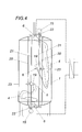
- Fig. 4 comprise the two drive means, one for the feed and one for the removal, a spindle guide 20 and one of the spindle guide 20 associated spindle 21, each of which is arranged outside of the container 1 and drivingly connected to the spindle 21 via a magnetic coupling 22, motor 15 rotatably driven is.
- the inlet or outlet 19 is provided on a spindle 23 having a spindle nut, which is guided both on the spindle guide 20, a profile, as well as on the spindle 21.
- the container bottom and the container ceiling temperature sensor 6 are assigned.
- the features of the exemplary embodiments can be combined in any way for a solution according to the invention.
- the number of loading and unloading devices per container is arbitrary.
Landscapes
- Engineering & Computer Science (AREA)
- Physics & Mathematics (AREA)
- Thermal Sciences (AREA)
- Mechanical Engineering (AREA)
- General Engineering & Computer Science (AREA)
- Chemical & Material Sciences (AREA)
- Combustion & Propulsion (AREA)
- Devices For Dispensing Beverages (AREA)
- Heat-Pump Type And Storage Water Heaters (AREA)
- Extraction Or Liquid Replacement (AREA)
Applications Claiming Priority (1)
| Application Number | Priority Date | Filing Date | Title |
|---|---|---|---|
| AT13482010 | 2010-08-12 |
Publications (2)
| Publication Number | Publication Date |
|---|---|
| EP2418449A2 true EP2418449A2 (fr) | 2012-02-15 |
| EP2418449A3 EP2418449A3 (fr) | 2014-08-13 |
Family
ID=44908504
Family Applications (1)
| Application Number | Title | Priority Date | Filing Date |
|---|---|---|---|
| EP11450099.4A Withdrawn EP2418449A3 (fr) | 2010-08-12 | 2011-08-08 | Dispositif d'introduction ou d'enlèvement d'un milieu liquide dans un ou à partir d'un récipient de stockage |
Country Status (2)
| Country | Link |
|---|---|
| EP (1) | EP2418449A3 (fr) |
| AT (1) | AT12587U1 (fr) |
Cited By (10)
| Publication number | Priority date | Publication date | Assignee | Title |
|---|---|---|---|---|
| WO2014070097A1 (fr) * | 2012-11-01 | 2014-05-08 | Skanska Sverige Ab | Buse pour la distribution d'un fluide |
| FR2998043A1 (fr) * | 2012-11-12 | 2014-05-16 | Sietar & Vti | Ballon d'eau chaude atmospherique permettant le puisage de l'eau la plus chaude et la limitation des pertes d'eau et de chaleur par les buees |
| WO2015032933A1 (fr) * | 2013-09-06 | 2015-03-12 | Gannet Limited | Système d'entrée pour un récipient de stockage thermique |
| RU2574756C1 (ru) * | 2012-11-01 | 2016-02-10 | Сканска Свериге Аб | Направляющая головка для распределения текучей среды |
| WO2016146724A1 (fr) * | 2015-03-18 | 2016-09-22 | Commissariat à l'énergie atomique et aux énergies alternatives | Système télescopique et flottant de distribution de fluide caloporteur pour un dispositif de stockage d'énergie thermique |
| US9518787B2 (en) | 2012-11-01 | 2016-12-13 | Skanska Svergie Ab | Thermal energy storage system comprising a combined heating and cooling machine and a method for using the thermal energy storage system |
| US9791217B2 (en) | 2012-11-01 | 2017-10-17 | Skanska Sverige Ab | Energy storage arrangement having tunnels configured as an inner helix and as an outer helix |
| US9823026B2 (en) | 2012-11-01 | 2017-11-21 | Skanska Sverige Ab | Thermal energy storage with an expansion space |
| CN108224788A (zh) * | 2018-01-29 | 2018-06-29 | 珠海格力电器股份有限公司 | 水箱、热水器及水温确定方法 |
| DE102022201429A1 (de) | 2022-02-11 | 2023-08-17 | Revincus GmbH | Verteiler für ein fluides Medium |
Family Cites Families (5)
| Publication number | Priority date | Publication date | Assignee | Title |
|---|---|---|---|---|
| DE4135453A1 (de) * | 1991-10-24 | 1993-04-29 | Rene Legere | Waermespeicherbehaelter fuer fluessige waermetraegermedien |
| DE19510152A1 (de) * | 1995-03-21 | 1996-09-26 | Raetz Karlheinz | Warmwasserspeicher für Solaranlagen |
| DE29810022U1 (de) * | 1997-06-07 | 1998-08-06 | Rapido Wärmetechnik GmbH, 41748 Viersen | Schichtenspeicher |
| DE19918990C1 (de) * | 1999-04-27 | 2001-01-11 | Plinius Ingenieurgesellschaft | Einrichtung zum Einschichten von Energiespeichermedien in einen Speicherbehälter |
| DE102005013314A1 (de) * | 2005-03-22 | 2006-09-28 | Ahs Investitionsgesellschaft Mbh & Co. Kg | Lade- und Entladevorrichtung für einen Flüssigkeits-Schichtspeicher |
-
2010
- 2010-08-12 AT ATGM8052/2011U patent/AT12587U1/de not_active IP Right Cessation
-
2011
- 2011-08-08 EP EP11450099.4A patent/EP2418449A3/fr not_active Withdrawn
Non-Patent Citations (1)
| Title |
|---|
| None |
Cited By (16)
| Publication number | Priority date | Publication date | Assignee | Title |
|---|---|---|---|---|
| US9511382B2 (en) | 2012-11-01 | 2016-12-06 | Skanska Sverige Ab | Nozzle for distribution of a fluid |
| US9518787B2 (en) | 2012-11-01 | 2016-12-13 | Skanska Svergie Ab | Thermal energy storage system comprising a combined heating and cooling machine and a method for using the thermal energy storage system |
| US9823026B2 (en) | 2012-11-01 | 2017-11-21 | Skanska Sverige Ab | Thermal energy storage with an expansion space |
| AU2013338645B2 (en) * | 2012-11-01 | 2015-09-10 | Skanska Sverige Ab | Nozzle for distribution of a fluid |
| JP2016503337A (ja) * | 2012-11-01 | 2016-02-04 | スカンスカ スヴェーリエ アクチボラグSkanska Sverige Ab | 流体を分配するノズル |
| RU2574756C1 (ru) * | 2012-11-01 | 2016-02-10 | Сканска Свериге Аб | Направляющая головка для распределения текучей среды |
| US9791217B2 (en) | 2012-11-01 | 2017-10-17 | Skanska Sverige Ab | Energy storage arrangement having tunnels configured as an inner helix and as an outer helix |
| US9657998B2 (en) | 2012-11-01 | 2017-05-23 | Skanska Sverige Ab | Method for operating an arrangement for storing thermal energy |
| WO2014070097A1 (fr) * | 2012-11-01 | 2014-05-08 | Skanska Sverige Ab | Buse pour la distribution d'un fluide |
| FR2998043A1 (fr) * | 2012-11-12 | 2014-05-16 | Sietar & Vti | Ballon d'eau chaude atmospherique permettant le puisage de l'eau la plus chaude et la limitation des pertes d'eau et de chaleur par les buees |
| WO2015032933A1 (fr) * | 2013-09-06 | 2015-03-12 | Gannet Limited | Système d'entrée pour un récipient de stockage thermique |
| FR3033877A1 (fr) * | 2015-03-18 | 2016-09-23 | Commissariat Energie Atomique | Systeme telescopique et flottant de distribution de fluide caloporteur pour un dispositif de stockage d'energie thermique |
| WO2016146724A1 (fr) * | 2015-03-18 | 2016-09-22 | Commissariat à l'énergie atomique et aux énergies alternatives | Système télescopique et flottant de distribution de fluide caloporteur pour un dispositif de stockage d'énergie thermique |
| CN108224788A (zh) * | 2018-01-29 | 2018-06-29 | 珠海格力电器股份有限公司 | 水箱、热水器及水温确定方法 |
| CN108224788B (zh) * | 2018-01-29 | 2024-03-19 | 珠海格力电器股份有限公司 | 水箱、热水器及水温确定方法 |
| DE102022201429A1 (de) | 2022-02-11 | 2023-08-17 | Revincus GmbH | Verteiler für ein fluides Medium |
Also Published As
| Publication number | Publication date |
|---|---|
| EP2418449A3 (fr) | 2014-08-13 |
| AT12587U1 (de) | 2012-08-15 |
Similar Documents
| Publication | Publication Date | Title |
|---|---|---|
| EP2418449A2 (fr) | Dispositif d'introduction ou d'enlèvement d'un milieu liquide dans un ou à partir d'un récipient de stockage | |
| EP3911907B1 (fr) | Dispositif et procédé pour la récupération de chaleur d'un milieu liquide | |
| DE202010004056U1 (de) | Schneckenkörper für eine Wasserkraftanlage | |
| AT515705B1 (de) | Wassergewinnung aus der Luft der Erdatmosphäre | |
| DE3011101A1 (de) | Dunstabzugshaube mit zuluftzufuehrung | |
| DE202011000051U1 (de) | Unterhalb einer Arbeits-/Tischfläche einbaubare Trinkwasseranlage | |
| DE2722888A1 (de) | Mit fuell- und zapfeinrichtungen versehener warmwasserspeicher | |
| WO2013087074A1 (fr) | Dispositif de collecte de liquide d'un composant de chaîne dynamique | |
| EP2546595A1 (fr) | Dispositif et procédé de refroidissement | |
| AT507233B1 (de) | Verfahren zur nutzung der abwärme insbesondere häuslicher abwässer | |
| DE202008006552U1 (de) | Wasserförderungsanlage | |
| EP1795818B1 (fr) | Procédé pour préparer de l'eau chaude utilisant un chauffe-eau et un accumulateur stratifié | |
| DE202012013215U1 (de) | Energiepfahl zur Erdwärmenutzung | |
| DE102019210703B4 (de) | Wärmespeichersystem und Verfahren zum Speichern von Wärme | |
| DE3116685C2 (fr) | ||
| DE4328984C2 (de) | Tankanlage zum Speichern von Bitumen | |
| EP2531799B1 (fr) | Échangeur de chaleur pour eaux usées, équipé d'un stockage tampon | |
| EP2918738A1 (fr) | Dispositif de ventilation pour une colonne montante comprenant un dispositif de réduction de l'eau de stagnation et procédé de fonctionnement d'une alimentation en eau | |
| EP2718650A2 (fr) | Procédé de refroidissement de fluides au moyen d'une vis transporteuse | |
| DE8711899U1 (de) | Fahrzeug, insbesondere Reisebus | |
| DE693472C (de) | Einrichtung zur Akkumulierung von heisser Fluessigkeit, insbesondere bei einem intermittierend arbeitenden Absorptionskaelteapparat | |
| DE19812003C2 (de) | Regenwasserauffangvorrichtung zum Einbau als Abzweigstück in Fallrohre | |
| DE1442954C (de) | Vorrichtung zum Aufheizen und Warmhalten von thermoplastischen Stoffen | |
| DE102011082164A1 (de) | Zusatzvorrichtung für einen Warmwasserspeicher | |
| DE3123253C2 (de) | Verfahren zum Erwärmen und Speichern einer Flüssigkeit, insbesondere von Brauchwasser |
Legal Events
| Date | Code | Title | Description |
|---|---|---|---|
| AK | Designated contracting states |
Kind code of ref document: A2 Designated state(s): AL AT BE BG CH CY CZ DE DK EE ES FI FR GB GR HR HU IE IS IT LI LT LU LV MC MK MT NL NO PL PT RO RS SE SI SK SM TR |
|
| AX | Request for extension of the european patent |
Extension state: BA ME |
|
| PUAI | Public reference made under article 153(3) epc to a published international application that has entered the european phase |
Free format text: ORIGINAL CODE: 0009012 |
|
| PUAL | Search report despatched |
Free format text: ORIGINAL CODE: 0009013 |
|
| AK | Designated contracting states |
Kind code of ref document: A3 Designated state(s): AL AT BE BG CH CY CZ DE DK EE ES FI FR GB GR HR HU IE IS IT LI LT LU LV MC MK MT NL NO PL PT RO RS SE SI SK SM TR |
|
| AX | Request for extension of the european patent |
Extension state: BA ME |
|
| RIC1 | Information provided on ipc code assigned before grant |
Ipc: F24H 9/12 20060101ALI20140709BHEP Ipc: F28D 20/00 20060101AFI20140709BHEP |
|
| STAA | Information on the status of an ep patent application or granted ep patent |
Free format text: STATUS: THE APPLICATION IS DEEMED TO BE WITHDRAWN |
|
| 18D | Application deemed to be withdrawn |
Effective date: 20150214 |