EP2418509B1 - Suivi de cible tridimensionnelle - Google Patents
Suivi de cible tridimensionnelle Download PDFInfo
- Publication number
- EP2418509B1 EP2418509B1 EP11177034.3A EP11177034A EP2418509B1 EP 2418509 B1 EP2418509 B1 EP 2418509B1 EP 11177034 A EP11177034 A EP 11177034A EP 2418509 B1 EP2418509 B1 EP 2418509B1
- Authority
- EP
- European Patent Office
- Prior art keywords
- target
- dimensional
- given
- track
- reference system
- Prior art date
- Legal status (The legal status is an assumption and is not a legal conclusion. Google has not performed a legal analysis and makes no representation as to the accuracy of the status listed.)
- Active
Links
Images


Classifications
-
- G—PHYSICS
- G01—MEASURING; TESTING
- G01S—RADIO DIRECTION-FINDING; RADIO NAVIGATION; DETERMINING DISTANCE OR VELOCITY BY USE OF RADIO WAVES; LOCATING OR PRESENCE-DETECTING BY USE OF THE REFLECTION OR RERADIATION OF RADIO WAVES; ANALOGOUS ARRANGEMENTS USING OTHER WAVES
- G01S13/00—Systems using the reflection or reradiation of radio waves, e.g. radar systems; Analogous systems using reflection or reradiation of waves whose nature or wavelength is irrelevant or unspecified
- G01S13/87—Combinations of radar systems, e.g. primary radar and secondary radar
- G01S13/878—Combination of several spaced transmitters or receivers of known location for determining the position of a transponder or a reflector
-
- G—PHYSICS
- G01—MEASURING; TESTING
- G01S—RADIO DIRECTION-FINDING; RADIO NAVIGATION; DETERMINING DISTANCE OR VELOCITY BY USE OF RADIO WAVES; LOCATING OR PRESENCE-DETECTING BY USE OF THE REFLECTION OR RERADIATION OF RADIO WAVES; ANALOGOUS ARRANGEMENTS USING OTHER WAVES
- G01S13/00—Systems using the reflection or reradiation of radio waves, e.g. radar systems; Analogous systems using reflection or reradiation of waves whose nature or wavelength is irrelevant or unspecified
- G01S13/02—Systems using reflection of radio waves, e.g. primary radar systems; Analogous systems
- G01S13/06—Systems determining position data of a target
- G01S13/42—Simultaneous measurement of distance and other co-ordinates
- G01S13/426—Scanning radar, e.g. 3D radar
-
- G—PHYSICS
- G01—MEASURING; TESTING
- G01S—RADIO DIRECTION-FINDING; RADIO NAVIGATION; DETERMINING DISTANCE OR VELOCITY BY USE OF RADIO WAVES; LOCATING OR PRESENCE-DETECTING BY USE OF THE REFLECTION OR RERADIATION OF RADIO WAVES; ANALOGOUS ARRANGEMENTS USING OTHER WAVES
- G01S13/00—Systems using the reflection or reradiation of radio waves, e.g. radar systems; Analogous systems using reflection or reradiation of waves whose nature or wavelength is irrelevant or unspecified
- G01S13/66—Radar-tracking systems; Analogous systems
- G01S13/72—Radar-tracking systems; Analogous systems for two-dimensional [2D] tracking, e.g. combination of angle and range tracking, track-while-scan radar
- G01S13/723—Radar-tracking systems; Analogous systems for two-dimensional [2D] tracking, e.g. combination of angle and range tracking, track-while-scan radar by using numerical data
- G01S13/726—Multiple target tracking
-
- G—PHYSICS
- G01—MEASURING; TESTING
- G01S—RADIO DIRECTION-FINDING; RADIO NAVIGATION; DETERMINING DISTANCE OR VELOCITY BY USE OF RADIO WAVES; LOCATING OR PRESENCE-DETECTING BY USE OF THE REFLECTION OR RERADIATION OF RADIO WAVES; ANALOGOUS ARRANGEMENTS USING OTHER WAVES
- G01S13/00—Systems using the reflection or reradiation of radio waves, e.g. radar systems; Analogous systems using reflection or reradiation of waves whose nature or wavelength is irrelevant or unspecified
- G01S13/86—Combinations of radar systems with non-radar systems, e.g. sonar, direction finder
-
- G—PHYSICS
- G01—MEASURING; TESTING
- G01S—RADIO DIRECTION-FINDING; RADIO NAVIGATION; DETERMINING DISTANCE OR VELOCITY BY USE OF RADIO WAVES; LOCATING OR PRESENCE-DETECTING BY USE OF THE REFLECTION OR RERADIATION OF RADIO WAVES; ANALOGOUS ARRANGEMENTS USING OTHER WAVES
- G01S5/00—Position-fixing by co-ordinating two or more direction or position line determinations; Position-fixing by co-ordinating two or more distance determinations
- G01S5/02—Position-fixing by co-ordinating two or more direction or position line determinations; Position-fixing by co-ordinating two or more distance determinations using radio waves
- G01S5/04—Position of source determined by a plurality of spaced direction-finders
Definitions
- the present invention relates to three-dimensional target tracking.
- the present invention allows a three-dimensional track of a target to be generated on the basis of two-dimensional and/or three-dimensional tracks generated by target location systems.
- target location system means a system/apparatus/device designed to locate one or more targets.
- target location system is intended to mean a system configured to generate and provide tracking data which indicate position and speed of a target, and which will be called “target tracks” hereinafter for description simplicity.
- Target tracks may comprise two-dimensional (2D) or three-dimensional (3D) positions and speeds.
- a two-dimensional (2D) position and a two-dimensional (2D) speed of a two-dimensional target track (2D) may be expressed in:
- a three-dimensional position (3D) and a three-dimensional speed (3D) of a three-dimensional target track (3D) may be expressed in:
- Examples of target location systems are:
- the two-dimensional position/speed/tracks will be called 2D positions/speed/tracks
- the three-dimensional position/speed/tracks will be called 3D position/speed/ tracks.
- target location systems which provide (i.e. generate) 2D tracks will be called 2D location systems
- target location systems which provide (i.e. generate) 3D tracks will be called 3D location systems.
- 2D and/or 3D location systems are currently used within the scope of maritime, air and land surveillance, e.g. for coast surveillance or in airports.
- German patent application DE 41 23 898 A1 a known air surveillance system which uses two 2D radars is described in German patent application DE 41 23 898 A1 .
- DE 41 23 898 A1 describes a 3D radar system which comprises two 2D radars separated by a known distance on a horizontal plane which transmit fan-shaped beams by turning in synchronized manner in opposite directions. Said 3D radar system calculates the height of a flying object by means of triangulation using the range measurements relative to the flying object provided by two 2D radars and the distances between said 2D radars and the intersection point of the beams.
- DE 41 23 898 A1 suggests to determine a relation between the angular positions of the beams as a function of the direction of flight and of the speed of the flying object.
- US 4 621 267 A describes a passive system and related methods for detecting the location of a plurality of N targets by using two X-beam antenna systems, by measuring the time delay between receipt of signals in the two planes of each X-beam which are received directly from the target, and by measuring the time delay between the receipt of signals in the two planes of each X-beam which signals are emitted by the target but reflected from a remote surface.
- target location systems which may provide 2D and/or 3D target tracks expressed in different formats, e.g. slant, bearing, geographic, spherical or Cartesian coordinates, are currently used in the scope of maritime, air and land surveillance, and for this reason the Applicant felt the need to develop said three-dimensional target tracking method so that said method allows a 3D target track to be generated on the basis of 2D and/or 3D tracks expressed in any format.
- the aforesaid object is reached by the present invention in that it relates to a three-dimensional target tracking method and to a system, a processor and a software program product configured to implement said three-dimensional target tracking method as defined in the appended claims.
- the present invention is actuated by means of a software program product comprising code portions adapted to implement, when the software program product is loaded in the memory of an electronic processor and executed by said electronic processor, the target tracking method described below.
- Figure 1 shows a block chart representing a three-dimensional target tracking system 1 according to the present invention.
- the three-dimensional target tracking system 1 comprises N target location systems 2, where N is an integer number higher than, or equal to, two, i.e. N ⁇ 2 .
- each track location system 2 is configured to generate respective 2D or 3D target tracks.
- the three-dimensional target tracking system 1 also comprises an electronic processor 3, e.g. a computer, which is coupled to N target location systems 2 to acquire therefrom the respective generated 2D or 3D tracks and is programmed to generate 3D target tracks on the basis of the acquired tracks in accordance with the three-dimensional track tracking method according to the present invention.
- an electronic processor 3 e.g. a computer, which is coupled to N target location systems 2 to acquire therefrom the respective generated 2D or 3D tracks and is programmed to generate 3D target tracks on the basis of the acquired tracks in accordance with the three-dimensional track tracking method according to the present invention.
- the N target location systems 2 may conveniently comprise:
- the 2D positions and 2D speeds contained in the 2D tracks acquired by the electronic processor 3 may be expressed in slant coordinates ( ⁇ , ⁇ ; V ⁇ , V ⁇ ) and/or bearing coordinates ( ⁇ , ⁇ ; V ⁇ , V ⁇ ) and/or geographic coordinates ( lat, long ; V lat , V long ) and/or Cartesian coordinates ( x , y ; V x , V y ), and the 3D positions and 3D speeds contained in the 3D tracks acquired by the electronic processor 3 may be expressed in spherical coordinates ( ⁇ , ⁇ , ⁇ ; V ⁇ , V ⁇ , V ⁇ ) and/or geographic coordinates ( lat, long, alt; V lat , V long , V alt ) and/or Cartesian coordinates ( x , y , z ; V x , V y , V z ).
- the electronic processor 3 in use acquires at least one track generated by a target location system 2 which either directly measures azimuth ⁇ of the targets, or which provide independent measurements which allow azimuth ⁇ of the targets to be determined.
- the electronic processor 3, in use preferably acquires at least one track, which comprises a position coordinate related to the azimuth ⁇ or which comprises at least two independent position coordinates which allow azimuth ⁇ to be determined.
- the electronic processor 3 in use, may conveniently acquire at least one track expressed in slant or bearing or spherical coordinates.
- the three-dimensional target tracking system 1 has an architecture in which the 3D tracking occurs on calculation centre level.
- a first 2D or 3D location system (hereinafter called system A for description simplicity) and a second 2D or 3D location system (hereinafter called system B for description simplicity again) which are positioned so as to have a shared coverage region, in which one or more targets are detected, system A generating a respective first 2D or 3D track and system B generating a respective second 2D or 3D track.
- system A a first 2D or 3D location system
- system B for description simplicity again
- system A generating a respective first 2D or 3D track
- system B generating a respective second 2D or 3D track.
- a correlation test based on a calculation of the height of the targets is carried out on the first and second tracks to check whether and which tracks belong to same real targets while calculating at the same time the respective heights in a single three-dimensional reference system.
- the 2D and/or 3D tracks belonging to a same target present in said shared coverage region can be correlated according to the present invention so as to calculate a respective height in a single three-dimensional reference system, and preferably also the height component of the respective speed.
- the three-dimensional tracking method according to the present invention allows a fused 3D track to be determined in which kinematics, i.e. position and speed, of a target present in the coverage region shared by at least two 2D location systems is complemented by the third dimension and calculated taking into account kinematics of the 2D tracks generated by said 2D location systems, thereby allowing the correlation, prediction and identification of the category, i.e. surface or air, of the fused 3D track to be improved. Therefore, the three-dimensional target tracking method according to the present invention allows a target with 3D kinematics to be identified as result of a fusion between two or more 2D tracks expressed in slant and/or bearing and/or geographic and/or Cartesian coordinates.
- the three-dimensional target tracking method according to the present invention allows a single fused 3D track to be determined on the basis of two or more 3D tracks expressed in spherical and/or geographical and/or Cartesian coordinates.
- systems A and B may be either both positioned on the ground, also at different heights, or one of said systems may be installed on moving means with a motion considered inertial, except for appropriate corrections (i.e. which can be approximated to a uniform rectilinear motion in the interval of time significant for 2D or 3D measurement, e.g. in the case of a radar, the scanning period T , typically from 1 to 10 seconds, at which the apparatus monitors and sends data), e.g. a ship or a satellite, while the other is positioned on the ground, or both said systems A and B can be installed on moving means, e.g. ships or satellites.
- the application of the three-dimensional target tracking method according to the invention is possible also when one or more target location systems are installed on respective moving means because, if the kinematics of the moving means are known, the kinematics of the 2D and/or 3D tracks may be corrected on the basis of pitch, roll and yaw movements of the moving means.
- Systems A and B are preferably positioned so that their respective distance D is equal to, or higher than, a maximum linear measuring error Err MAX of said systems, i.e. using a mathematical formalism, the distance D between the systems A and B satisfied the following mathematical constrain: Err MAX ⁇ D .
- Err MAX max ⁇ Err A - MAX ⁇ Err B - MAX
- the measuring error shape of a measuring apparatus is known to depend on the nature of measured datum.
- a PSR generally has, for range measurements, a constant range measuring error ⁇ and, for azimuth measurements, a constant azimuth measuring error 2 ⁇ ⁇ which, however, give rise to a total measuring error which, for a target "seen” by the PSR under the same azimuth angle equal to the measuring error in azimuth 2 ⁇ ⁇ , varies according to the distance of said target from the PSR.
- the total measuring error is greater in amplitude the farther the target to be located is from the centre of the PSR.
- figure 2 schematically shows how the total measuring error of a PSR 5, having a constant ⁇ range measuring error and a constant azimuth 2 ⁇ ⁇ measuring error, varies according to the distance from the PSR 5 of a target 6 "seen" by PSR 5 on a reference plane under the same azimuth angle equal to the azimuth measuring error 2 ⁇ ⁇ , i.e. "seen” by PSR 5 on the reference plane in a circular section identified by an angle which is equal to the azimuth measuring error 2 ⁇ ⁇ and which has the PSR 5 as vertex, said reference plane being perpendicular to the rotation axis (not shown in figure 2 ) of the PSR 5.
- figure 2 shows, for each distance of the target 6 from the PSR 5, a respective total measuring error which is represented by a respective portion of said circular sector indicated with reference numerals 7, 8, 9 and 10, respectively.
- the maximum linear measuring error Err A-MAX of the PSR A is equal to the angular error rectified at the maximum coverage distance C A-MAX , i.e. is equal to 2 ⁇ ⁇ A C A-MAX .
- the system B is a PSR which has an azimuth measuring error 2 ⁇ ⁇ B and a maximum coverage C B-MAX
- the maximum linear measuring error Err B-MAX of the PSR B is equal to the angular error rectified at the maximum coverage distance C B - MAX , i.e. is equals to 2 ⁇ ⁇ B C B-MAX .
- the PSRs A and B are preferably positioned so that their reciprocal distance D satisfies the mathematical constraint (1) that, in the assumption of two PRSs, becomes: 2 ⁇ ⁇ ⁇ ⁇ ⁇ C ⁇ MAX ⁇ D , where 2 ⁇ ⁇ denotes the azimuth measuring error of the PSR having the highest maximum linear measuring error between the PSRs A and B and C ⁇ MAX denotes the maximum coverage of the PSR having the highest maximum linear measuring error between the PSRs A and B .
- the distance D between the PSRs A and B is equal to, or greater than, 1 Km.
- figure 3 schematically shows on a reference plane a first PSR 11 having a first azimuth measuring error 2 ⁇ ⁇ 11 and a first maximum coverage C 11 and a second PSR 12 having a second azimuth measuring error 2 ⁇ ⁇ 12 and a second maximum coverage C 12 , which are distanced by a distance D such as to satisfy the mathematical constraint (2a), said reference plane being perpendicular to the rotation axes (not shown in figure 3 ) of the first PSR 11 and of the second PSR 12 (said rotation axes, in the example shown in figure 3 , being assumed parallel to each other) .
- D ' indicates the projection on said reference plane of the distance D between the first PSR 11 and the second PSR 12.
- figure 3 shows a first circle 13 which has as centre the first PSR 11 and as radius the first maximum coverage C 11 and which thus represents the coverage area of the first PSR 11 on said reference plane, and a second circle 14 which has the second PSR 12 as a centre and the second maximum coverage C 12 as the radius, and which thus represents the coverage area of the second PSR 12 on said reference plane.
- the first circle 13 and the second circle 14 have an intersection 15 which represents a shared coverage region of the PSRs 11 and 12 on said reference plane.
- Radio direction finding systems instead display an azimuth measuring error 2 ⁇ ⁇ which is substantially equal to the elevation measuring error 2 ⁇ ⁇ . Therefore, if the system A is a radio direction finding system which has an azimuth/elevation measuring error 2 ⁇ ⁇ A ⁇ / ⁇ and a maximum coverage C A-MAX , then the maximum linear measuring error Err A-MAX of said system A is equal to the angular error rectified at the maximum coverage distance C A-MAX , i.e. is equal to 2 ⁇ ⁇ A ⁇ / ⁇ C A-MAX .
- the system B is a radio direction finding system which has an azimuth/elevation measuring error 2 ⁇ ⁇ B ⁇ / ⁇ and a maximum coverage C B-MAX
- the maximum linear mea.suring error Err B-MAX of said system B is equal to the angular error rectified at the maximum coverage distance C B-MAX , i.e. is equal to 2 ⁇ ⁇ B ⁇ / ⁇ ⁇ C E - MAX .
- the radio direction finding systems A and B are preferably positioned so that their reciprocal distance D satisfies the mathematical constraint (1) which, in the assumption of two radio direction finding systems, becomes: 2 ⁇ ⁇ ⁇ ⁇ / ⁇ ⁇ C ⁇ MAX ⁇ D , where 2 ⁇ ⁇ ⁇ ⁇ / ⁇ denotes the azimuth/ elevation measuring error of the radio direction finding system having the highest maximum linear measuring error radio between the direction finding systems A and B and C ⁇ MAX denotes the maximum coverage of the radio direction finding system having the highest maximum linear measuring error between the radio direction finding systems A and B .
- mathematical constraint (1) depends on the capacity of the two systems A and B to distinguish two real objects. Therefore, systems A and B may be considered non-homocentric and not co-located if each system and a real object to be tracked can be "seen" in distinct positions by the other system.
- mathematical constraint (1) takes into consideration the maximum linear measuring error Err MAX so as to always ensure the possibility of carrying out a triangulation to determine a three-dimensional track of a target intercepted by the systems A and B , independently from the position of said target in the coverage region shared by said systems A and B .
- the correlation test is preferably carried out on the basis of the 2D and/or 3D tracks generated by the systems A and B only if the distance D between said systems A and B satisfies the mathematical constraint (1).
- a test is carried out on tracks ST A and ST B , which are related to the same time t, to check whether they are related to a same single target. Furthermore, if the tracks ST A and ST B related to a same single target, the present invention allows the height of said target to be also calculated, while carrying out said correlation test.
- the correlation test is verified by the tracks ST A and ST B if the following three conditions are satisfied:
- the tracks ST A and ST B relate to a same single target for which a 3D track MST ( ⁇ , ⁇ , ⁇ ; V ⁇ , V ⁇ , V ⁇ ) at the time t in an absolute reference system O is also generated.
- Figure 4 schematically shows an absolute reference system O used to carry out the correlation test of the tracks ST A and ST B according to said preferred embodiment of the present invention.
- the absolute reference system O is a system of three-dimensional Cartesian coordinates zxy .
- figure 4 shows:
- the 2D position vectors contained in tracks ST A and ST B if projected on the horizontal reference plane PO must have a non-null intersection (i.e. P 0 ( x 0 , y 0 , 0 )) in order to be related to a same single target.
- intersection condition is verified, i.e. is satisfied by the 2D slant tracks ST A and ST B , if said Cartesian coordinates ( x 0 , y 0 ) of the intersection point P 0 can be calculated.
- the method goes on to checking the triangle-inequality-related condition, i.e. checks whether the position vectors 2D contained in the tracks ST A and ST B and the distance D between the centers O A and O B of the systems A and B satisfy the triangle inequality (3) or not.
- the triangle inequality (3) becomes: ⁇ A + ⁇ B ⁇ D ⁇ ⁇ , that is ⁇ A + ⁇ B ⁇ X A - X B 2 + Y A - Y B 2 + Z A - Z B 2 ⁇ ⁇ ⁇ ⁇
- the method goes on to checking the elevation-related condition, i.e. checks whether the tracks ST A and ST B allow a same height to be determined for the first and second targets.
- the elevation angles ⁇ A and ⁇ B at which the same single target is seen in the first relative reference system of the system A and in the second relative reference system of the system B, respectively, can be calculated.
- mathematical formulae (8), (9), (10), (11) and (12) may still be used to verify whether the elevation-related condition is satisfied or not. Furthermore, if said elevation-related condition, is satisfied, the height h o of the same single target seen by the two systems A and B is also determined.
- one of the two 2D tracks is instead a 2D track expressed in Cartesian or geographic coordinates
- a correlation test may be carried out, which is different from that described above with regards to two slant and/or bearing tracks .
- the system A is a Satellite location terminal which provides a 2D track of a first target expressed in geographic ST A (lat, long; V lat , V long ) or Cartesian ST A (x A ,Y A ; V xA , V yA ) coordinates, the following may be calculated:
- the method thus imposes that the Cartesian coordinates (x 0 , y 0 ) of the point P 0 are equal to the Cartesian coordinates x A O ⁇ y A O of the first target in the absolute reference system O .
- intersection-related condition is verified, i.e. it is satisfied by the 2D tracks ST A and ST B , if the mathematical relation (13) is satisfied.
- the mathematical relation (13) is still valid and thus can still be used for verifying the intersection-related condition.
- the correlation test does not comprise the verification of the triangle-inequality-related condition, but directly includes the verification of the elevation-related condition, in particular a direct calculation of the height.
- Two h o values are obtained by solving the equation (14): one corresponding to the plus sign and the other to the minus sign of the formula (14).
- running domain considerations is needed to choose the right physical solution. For example, the case of negative height may be excluded and the solution can be compared with the previous prediction data..
- the height coordinate contained in said 3D track can be used to choose the correct height value h 0 .
- the height coordinate contained in said 3D track may be used to choose the correct height value h 0 .
- the method goes on to verifying the elevation-related condition by determining the elevation angles ⁇ A and ⁇ B by means of a triangulation carried out on a reference plane zx perpendicular to the surface of the Earth and passing through the centre O A of the system A and the centre O B of the system B.
- figure 5 shows:
- a 3D speed is also preferably determined on the basis of the tracks ST A and ST B and, in particular, if the two tracks ST A and ST B are 2D tracks, a respective elevation component of the respective speed contained in the 2D track is determined for each of the two 2D tracks ST A and ST B .
- the first relative reference system of the system A , the second relative reference system of the system B and the absolute reference system O have the same orientation with the respective vertical axis to the respective zenith and axis y oriented to the North.
- first relative reference system of the system A the second relative reference system of the system B and the absolute reference system O have the same orientation, with the respective vertical axis to the respective zenith and axis y oriented to the North, if the distance D between the systems A and B does not exceed 25 Km.
- the Earth may be approximated to a plane, the zeniths of the relative reference systems of the systems A and B may be considered parallel, and North may be considered in common at low latitudes.
- geocentric coordinates are then preferably used or the orientations of the relative reference systems are corrected by means of Euler angles.
- the present invention allows a 3D track to be determined as fusion of two or more 2D or 3D tracks which come from different target location systems, relate to a same instant in time and which, if they satisfy the correlation test, are deemed to relate to a same real object.
- the three-dimensional target tracking method according to the present invention finds advantageous, but not exclusive application in maritime, land and air surveillance.
- the three-dimensional tracking method according to the present invention allows possible air tracks to be ignored.
- the correlation of the kinematics of a target with the calculation of the height allows ambiguity to be solved if aircrafts flying at low height, e.g. helicopters or airplanes, which appear on the horizon, interfere with the naval surface tracks.
- the three-dimensional tracking method according the present invention allows low height air tracks to be discriminated and located with greater accuracy during landing and take-off in the airport maneuvering areas.
- the three-dimensional tracking method according to the present invention allows aircraft air tracks to be discriminated and located with greater accuracy.
- the present invention could be advantageously exploited to provide a portable air surveillance system which, by only using 2D targets, is capable of locating 3D air tracks with accuracy.
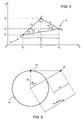
- figure 6 schematically shows:
- H R T sec ⁇ t arg et - R T ⁇ Err MAX .
- the 2D tracks of a second location system 2D which may be correlated with said first 2D track may be conveniently sought about a first 2D track, because the position of the target seen by both 2D location systems falls within a limited correlation window which depends on the 2D location system error and on the history of the target.
- a limited correlation window which depends on the 2D location system error and on the history of the target.
- primary coastal or naval radars may import the height calculation without needing to modify the criteria to search the tracks which may be correlated, which criteria are limited to the error windows about the first 2D track.
- H R T sec ⁇ t arg et - R T > Err MAX
- the search criterion for the air domain includes the case of surface domain, which is thus a subset.
- the three-dimensional tracking method with search criteria on all 2D tracks works in any domain.
- the present invention allows a single three-dimensional track of a target present in said shared coverage region to be determined on the basis of kinematic data produced by at least two 2D or 3D location systems having a shared coverage region.
- the three-dimensional target tracking method according to the present invention is applicabl.e to any number N of target location systems, with N > 1 , which may be all positioned on the ground, even at different heights, or may be all installed on respective moving means, or some of which may be installed on respective moving means and others may be positioned on the ground.
Landscapes
- Engineering & Computer Science (AREA)
- Radar, Positioning & Navigation (AREA)
- Remote Sensing (AREA)
- Physics & Mathematics (AREA)
- General Physics & Mathematics (AREA)
- Computer Networks & Wireless Communication (AREA)
- Radar Systems Or Details Thereof (AREA)
- Length Measuring Devices By Optical Means (AREA)
- Testing, Inspecting, Measuring Of Stereoscopic Televisions And Televisions (AREA)
Claims (11)
- Méthode de suivi de cible tridimensionnelle comprenant :• l'acquisition d'une première trace exprimée en coordonnées rabattues ou azimutales ou sphériques et générée par un premier système de localisation de cible (2, 11, A) ayant une première zone de couverture (13), ladite première trace comprenant une première position d'une première cible à un temps donné dans un premier système de référence relatif du premier système de localisation de cible (2, 11, A) ;• l'acquisition d'une seconde trace exprimée en coordonnées rabattues ou azimutales ou sphériques ou géographiques ou cartésiennes et générée par un second système de localisation de cible (2, 12, B) ayant une seconde zone de couverture (14) chevauchant partiellement la première zone de couverture (13) dans une région de couverture (15) partagée par les deux systèmes de localisation de cible (2, 11, 12, A, B), ladite seconde trace comprenant une deuxième position d'une seconde cible au temps donné dans un second système de référence relatif du second système de localisation de cible (2, 12, B) ; et• la réalisation d'un test de corrélation sur la base des traces acquises ;dans laquelle, si la seconde trace acquise est exprimée en coordonnées rabattues ou azimutales ou sphériques, le test de corrélation inclus :• la détermination d'une première direction identifiée sur un plan de référence (PO) d'un système de référence tridimensionnel donné, par la première position et par une position du premier système de localisation de cible ;• la détermination d'une seconde direction identifiée, sur le plan de référence (PO) du système de référence tridimensionnel donné, par la deuxième position et par une position du second système de localisation de cible ;• la vérification consistant à savoir si la première direction et la seconde direction se coupent l'une l'autre ou coïncident ;• si la première direction et la seconde direction se coupent l'une l'autre ou coïncident, la vérification consistant à savoir si la première position, la deuxième position et une distance donnée (D) entre les deux systèmes de localisation de cible (2, 11, 12, A, B) satisfont une condition liée à l'inégalité triangulaire ;• si la première position, la deuxième position et la distance donnée (D) satisfont la condition liée à l'inégalité triangulaire, la vérification consistant à savoir si une même hauteur (ho) est déterminée pour la première cible et la seconde cible dans le système de référence tridimensionnel donné sur la base de la première position et de la deuxième position ; et• si une même hauteur (ho) est déterminée pour la première cible et la seconde cible dans le système de référence tridimensionnel donné, la détection que la première cible et la seconde cible représentent une seule et même cible (T, P) présente dans la région de couverture partagée (15) ;dans laquelle, si la seconde trace acquise est exprimée en coordonnées géographiques ou cartésiennes, le test de corrélation inclut :• la détermination d'une première direction identifiée sur le plan de référence (PO) du système de référence tridimensionnel donné par la première position et par une position du premier système de localisation de cible ;• la détermination d'une troisième position de la seconde cible sur le plan de référence (PO) du système de référence tridimensionnel donné sur la base de la deuxième position et d'une position d'origine du second système de référence relatif dans le système de référence tridimensionnel donné ;• la vérification consistant à savoir si la première direction passe par la troisième position ;• si la première position passe par la troisième position, la vérification consistant à savoir si une même hauteur (ho) est déterminée pour la première cible et la seconde cible dans le système de référence tridimensionnel donné sur la base de la première position et de la deuxième position ; et• si une même hauteur (ho) est déterminée pour la première cible et la seconde cible dans le système de référence tridimensionnel donné, la détection que la première cible et la seconde cible représentent une seule et même cible (T, P) présente dans la région de couverture partagée (15) ;et dans laquelle, si la première cible et la seconde cible représentent une seule et même cible (T, P) présente dans la région de couverture partagée (15), la méthode comprend en outre la génération d'une trace tridimensionnelle qui comprend une position tridimensionnelle de ladite seule et même cible (T, P) au temps donné dans le système de référence tridimensionnel donné, ladite position tridimensionnelle comprenant la même hauteur (ho) déterminée pour la première cible et la seconde cible dans le système de référence tridimensionnel donné.
- Méthode selon la revendication 1, dans laquelle le test de corrélation est réalisé si une distance donnée (D) entre les deux systèmes de localisation de cible (2, 11, 12, A, B) satisfait une relation donnée avec une erreur de mesure linéaire maximale donnée des deux systèmes de localisation de cible (2, 11, 12, A, B).
- Méthode selon la revendication 2, dans laquelle le test de corrélation est réalisé si la distance donnée (D) est supérieure ou égale à ladite erreur de mesure linéaire maximale.
- Méthode selon la revendication 3, dans laquelle l'erreur de mesure linéaire maximale donnée est égale à la plus grande d'une première erreur de mesure linéaire maximale du premier système de localisation de cible (2, 11, A) et d'une seconde erreur de mesure linéaire maximale du second système de localisation de cible (2, 12, B).
- Méthode selon l'une quelconque des revendications précédentes, dans laquelle, si la seconde trace acquise est exprimée en coordonnées rabattues ou azimutales ou sphériques, la première position, la deuxième position et la distance donnée (D) satisfont la condition liée à l'inégalité triangulaire si une somme d'une première distance (ρA) de la première cible au premier système de localisation de cible (2, 11, A) dans le premier système de référence relatif et d'une seconde distance (ρB) de la seconde cible au second système de localisation de cible (2, 12, B) dans le second système de référence relatif est supérieure ou égale à ladite distance donnée (D) diminuée et augmentée par une erreur de mesure donnée des deux systèmes de localisation de cible (2, 11, 12, A, B).
- Méthode selon la revendication 5, dans laquelle l'erreur de mesure donnée des deux systèmes de localisation de cible (2, 11, 12, A, B) est égale à une somme d'une première erreur de mesure de portée du premier système de localisation de cible (2, 11, A) et d'une seconde erreur de mesure de portée du second système de localisation de cible (2, 12, B).
- Méthode selon l'une quelconque des revendications précédentes, dans laquelle la première trace acquise comprend en outre une première vitesse de la première cible au temps donné dans le premier système de référence relatif ;
dans laquelle la seconde trace acquise comprend en outre une seconde vitesse de la seconde cible au temps donné dans le second système de référence relatif ;
et dans laquelle la génération d'une trace tridimensionnelle comprend le calcul d'une vitesse tridimensionnelle de ladite seule et même cible (T, P) au temps donné dans le système de référence tridimensionnel donné sur la base de la première position, de la deuxième position, de la première vitesse, de la seconde vitesse, et de la même hauteur (ho) déterminée pour la première cible et la seconde cible dans le système de référence tridimensionnel donné, ladite trace tridimensionnelle comprenant également la vitesse tridimensionnelle calculée. - Méthode selon la revendication 7, dans laquelle la vitesse tridimensionnelle est calculée également sur la base de :• une première quantité, qui est liée à la même hauteur (ho) déterminée pour la première cible et la seconde cible dans le système de référence tridimensionnel donné et indique une première hauteur de la première cible au temps donné dans le premier système de référence relatif ; et• une seconde quantité, qui est liée à la même hauteur (ho) déterminée pour la première cible et la seconde cible dans le système tridimensionnel donné et indique une seconde hauteur de la seconde cible au temps donné dans le second système de référence relatif.
- Processeur (3) configuré pour implémenter la méthode de suivi de cible tridimensionnelle revendiquée dans l'une quelconque des revendications précédentes.
- Système de suivi de cible tridimensionnelle (1) comprenant :• un premier système de localisation de cible (2, 11, A) ayant une première zone de couverture (13) et configuré pour générer des premières traces de cible exprimées en coordonnées rabattues ou azimutales ou sphériques ;• au moins un système de localisation de cible (2, 12, B) ayant une seconde zone de couverture (14) chevauchant partiellement la première zone de couverture (13) et configuré pour générer des secondes traces de cible exprimées en coordonnées rabattues ou azimutales ou sphériques ou géographiques ou cartésiennes ; et• le processeur (3) revendiqué dans la revendication 9, ledit processeur (3) étant couplé au premier système de localisation de cible (2, 11, A) permettant d'acquérir les premières traces de cible générées par ledit premier système de localisation de cible (2, 11, A), et au second système de localisation de cible (2, 12, B) permettant d' acquérir les secondes traces de cible générées par ledit second système de localisation de cible (2, 12, B).
- Produit de programme logiciel comprenant des portions de code logiciel chargeable dans une mémoire de processeur (3), exécutable par ledit processeur (3), et tel à amener, une fois exécuté, ledit processeur (3) à être configuré pour implémenter la méthode de suivi de cible tridimensionnelle revendiquée dans l'une quelconque des revendications 1 à 8.
Applications Claiming Priority (1)
| Application Number | Priority Date | Filing Date | Title |
|---|---|---|---|
| ITTO2010A000685A IT1401374B1 (it) | 2010-08-09 | 2010-08-09 | Tracciamento tridimensionale multisensore basato su tracce bidimensionali acquisite da tracciatori di sensori di localizzazione di bersagli |
Publications (3)
| Publication Number | Publication Date |
|---|---|
| EP2418509A1 EP2418509A1 (fr) | 2012-02-15 |
| EP2418509A8 EP2418509A8 (fr) | 2012-05-16 |
| EP2418509B1 true EP2418509B1 (fr) | 2013-07-17 |
Family
ID=43567943
Family Applications (1)
| Application Number | Title | Priority Date | Filing Date |
|---|---|---|---|
| EP11177034.3A Active EP2418509B1 (fr) | 2010-08-09 | 2011-08-09 | Suivi de cible tridimensionnelle |
Country Status (4)
| Country | Link |
|---|---|
| US (1) | US20120032835A1 (fr) |
| EP (1) | EP2418509B1 (fr) |
| CN (1) | CN102411142B (fr) |
| IT (1) | IT1401374B1 (fr) |
Families Citing this family (19)
| Publication number | Priority date | Publication date | Assignee | Title |
|---|---|---|---|---|
| US20130229298A1 (en) * | 2012-03-02 | 2013-09-05 | The Mitre Corporation | Threaded Track Method, System, and Computer Program Product |
| WO2014012567A1 (fr) * | 2012-07-18 | 2014-01-23 | Unify Gmbh & Co. Kg | Procédé de transport d'informations de localisation représentant l'emplacement physique d'un dispositif de communication, produit programme d'ordinateur destiné à exécuter le procédé et dispositif de communication destiné à transporter les informations de localisation |
| JP6210845B2 (ja) * | 2013-11-01 | 2017-10-11 | 三菱電機株式会社 | 目標追尾装置及び目標追尾方法 |
| CN104820441A (zh) * | 2015-04-30 | 2015-08-05 | 国家电网公司 | 一种无线网桥自动测向和调整方法及系统 |
| US10421544B2 (en) * | 2016-04-08 | 2019-09-24 | Rosemount Aerospace Inc. | Systems and methods for positioning a hoist and hook |
| CN105676865B (zh) * | 2016-04-12 | 2018-11-16 | 北京博瑞云飞科技发展有限公司 | 目标跟踪方法、装置和系统 |
| CN106303409B (zh) * | 2016-07-27 | 2019-04-02 | 阔地教育科技有限公司 | 一种目标对象联合跟踪方法及目标对象联合跟踪装置 |
| WO2018136947A1 (fr) * | 2017-01-23 | 2018-07-26 | Ohio University | Système et procédé de détection et de rapport de cibles par liaisons de données |
| CN107870341B (zh) * | 2017-11-08 | 2021-06-08 | 上海航天控制技术研究所 | 一种基于两个标志点矢量信息的卫星自主定位方法 |
| CN110579738B (zh) * | 2018-06-11 | 2021-06-25 | 深圳市优必选科技有限公司 | 运动目标方向角获取方法及终端设备 |
| CN110082781B (zh) * | 2019-05-20 | 2021-12-17 | 东北大学秦皇岛分校 | 基于slam技术与图像识别的火源定位方法及系统 |
| CN110346789B (zh) * | 2019-06-14 | 2021-06-18 | 北京雷久科技有限责任公司 | 一种多面阵雷达系统及数据融合处理方法 |
| CN111009012B (zh) * | 2019-11-29 | 2023-07-28 | 四川沃洛佳科技有限公司 | 一种基于计算机视觉的无人机测速方法、存储介质及终端 |
| CN112946587B (zh) * | 2019-12-10 | 2024-05-17 | 华为技术有限公司 | 通信方法和装置 |
| CN111766582B (zh) * | 2020-07-13 | 2021-11-23 | 成都汇蓉国科微系统技术有限公司 | 一种双基前视sar图像几何校正方法及装置 |
| CN112526508B (zh) * | 2020-11-26 | 2022-11-11 | 上海机电工程研究所 | 双站雷达联合目标定位方法和系统 |
| CN112946619B (zh) * | 2021-02-06 | 2024-03-19 | 宁波泽为科技有限公司 | 雷达探测目标绝对定位的方法、装置、系统及介质 |
| CN114333321B (zh) * | 2021-12-31 | 2023-09-12 | 北京荣顺智行科技开发有限公司 | 路侧装置 |
| CN115164891A (zh) * | 2022-06-17 | 2022-10-11 | 中国航空无线电电子研究所 | 一种面向航空航迹融合算法软件的验证方法 |
Family Cites Families (13)
| Publication number | Priority date | Publication date | Assignee | Title |
|---|---|---|---|---|
| US3696418A (en) * | 1970-09-14 | 1972-10-03 | Nasa | Altitude measuring system |
| DE3430453A1 (de) * | 1984-08-18 | 1986-03-06 | Standard Elektrik Lorenz Ag, 7000 Stuttgart | System zur positionsbestimmung eines ballons |
| US4621267A (en) * | 1984-09-28 | 1986-11-04 | The Boeing Company | Bearing intersection deghosting by altitude comparison system and methods |
| DE4123898A1 (de) * | 1991-07-18 | 1993-01-21 | Siemens Ag | Dreidimensional arbeitendes radarsystem |
| US5138321A (en) * | 1991-10-15 | 1992-08-11 | International Business Machines Corporation | Method for distributed data association and multi-target tracking |
| SE515621C2 (sv) * | 1995-05-08 | 2001-09-10 | Ericsson Telefon Ab L M | Förfarande vid lägesbestämning |
| US6002358A (en) * | 1998-08-18 | 1999-12-14 | Northrop Grumman Corporation | Method and apparatus for determining whether two radar tracks represent the same physical object |
| US7358892B2 (en) * | 2005-04-04 | 2008-04-15 | Raytheon Company | System and method for coherently combining a plurality of radars |
| DE102005041705A1 (de) * | 2005-09-02 | 2007-03-15 | Oerlikon Contraves Ag | Verfahren zur Raum-/Luftraumüberwachung |
| US7508335B2 (en) * | 2006-12-20 | 2009-03-24 | Raytheon Company | Multiple sensor processing |
| GB0710209D0 (en) * | 2007-05-29 | 2007-07-04 | Cambridge Consultants | Radar system |
| GB0822468D0 (en) * | 2008-12-10 | 2009-01-14 | Qinetiq Ltd | Method for mitigating the effects of clutter and interference on a radar system |
| US8044841B1 (en) * | 2009-03-02 | 2011-10-25 | Lockheed Martin Corporation | Geometry and sensitivity weighted dynamic multi-sensor selection system and method |
-
2010
- 2010-08-09 IT ITTO2010A000685A patent/IT1401374B1/it active
-
2011
- 2011-08-09 EP EP11177034.3A patent/EP2418509B1/fr active Active
- 2011-08-09 US US13/206,036 patent/US20120032835A1/en not_active Abandoned
- 2011-08-09 CN CN201110227767.4A patent/CN102411142B/zh not_active Expired - Fee Related
Also Published As
| Publication number | Publication date |
|---|---|
| EP2418509A1 (fr) | 2012-02-15 |
| US20120032835A1 (en) | 2012-02-09 |
| CN102411142B (zh) | 2015-04-15 |
| CN102411142A (zh) | 2012-04-11 |
| IT1401374B1 (it) | 2013-07-18 |
| ITTO20100685A1 (it) | 2012-02-10 |
| EP2418509A8 (fr) | 2012-05-16 |
Similar Documents
| Publication | Publication Date | Title |
|---|---|---|
| EP2418509B1 (fr) | Suivi de cible tridimensionnelle | |
| US6593875B2 (en) | Site-specific doppler navigation system for back-up and verification of GPS | |
| US8204677B2 (en) | Tracking method | |
| EP2556603B1 (fr) | Chevauchement de faisceaux étroits à avantage de géo-localisation | |
| US8630804B2 (en) | Method for geolocating an object by multitelemetry | |
| EP2082259B1 (fr) | Procédés et appareils servant à estimer l'altitude cible dans un système de radar bidimensionnel | |
| US20070222664A1 (en) | Method and system for correlating radar position data with target identification data, and determining target position using round trip delay data | |
| Dobrev et al. | Radar-based high-accuracy 3D localization of UAVs for landing in GNSS-denied environments | |
| CN108693545A (zh) | 基于星载ads-b的异常目标定位方法 | |
| JP2021184280A (ja) | 航空機着陸システム及び方法 | |
| Goswami et al. | Potential of multi constellation global navigation satellite system in indian missile test range applications | |
| US7688264B2 (en) | Method and apparatus for passive single platform geo-location | |
| Grabbe et al. | Geo-location using direction finding angles | |
| US5999130A (en) | Determination of radar threat location from an airborne vehicle | |
| US6933879B2 (en) | Method and system for localizing a target in an interrogation-response system | |
| Plšek et al. | Passive Coherent Location and Passive ESM tracker systems synergy | |
| US20180231632A1 (en) | Multi-receiver geolocation using differential gps | |
| de Ponte Müller et al. | Characterization of a laser scanner sensor for the use as a reference system in vehicular relative positioning | |
| US11709251B1 (en) | Radar node with full azimuthal coverage, and associated surveillance methods | |
| RU2860835C1 (ru) | Способ юстировки корабельной РЛС и комплект средств юстировки корабельной РЛС для реализации такого способа | |
| JP2003232843A (ja) | 電波測距装置 | |
| Ostroumov | Position detection by angular method in air navigation. | |
| Baine et al. | Algorithm for three-dimensional geodetic positioning based on measurements of automatic dependent surveillance-broadcast signals | |
| Vitiello et al. | Sensing Small Uncrewed Aerial Vehicles With Distributed Radars for Advanced Air Mobility Surveillance | |
| Baine et al. | Algorithm for geodetic positioning based on angle-of-arrival of automatic dependent surveillance-broadcasts |
Legal Events
| Date | Code | Title | Description |
|---|---|---|---|
| AK | Designated contracting states |
Kind code of ref document: A1 Designated state(s): AL AT BE BG CH CY CZ DE DK EE ES FI FR GB GR HR HU IE IS IT LI LT LU LV MC MK MT NL NO PL PT RO RS SE SI SK SM TR |
|
| AX | Request for extension of the european patent |
Extension state: BA ME |
|
| PUAI | Public reference made under article 153(3) epc to a published international application that has entered the european phase |
Free format text: ORIGINAL CODE: 0009012 |
|
| 17P | Request for examination filed |
Effective date: 20120814 |
|
| GRAP | Despatch of communication of intention to grant a patent |
Free format text: ORIGINAL CODE: EPIDOSNIGR1 |
|
| GRAS | Grant fee paid |
Free format text: ORIGINAL CODE: EPIDOSNIGR3 |
|
| GRAA | (expected) grant |
Free format text: ORIGINAL CODE: 0009210 |
|
| RAP1 | Party data changed (applicant data changed or rights of an application transferred) |
Owner name: SELEX ES S.P.A. |
|
| AK | Designated contracting states |
Kind code of ref document: B1 Designated state(s): AL AT BE BG CH CY CZ DE DK EE ES FI FR GB GR HR HU IE IS IT LI LT LU LV MC MK MT NL NO PL PT RO RS SE SI SK SM TR |
|
| REG | Reference to a national code |
Ref country code: GB Ref legal event code: FG4D |
|
| REG | Reference to a national code |
Ref country code: CH Ref legal event code: EP |
|
| REG | Reference to a national code |
Ref country code: IE Ref legal event code: FG4D |
|
| REG | Reference to a national code |
Ref country code: AT Ref legal event code: REF Ref document number: 622540 Country of ref document: AT Kind code of ref document: T Effective date: 20130815 |
|
| REG | Reference to a national code |
Ref country code: DE Ref legal event code: R096 Ref document number: 602011002378 Country of ref document: DE Effective date: 20130912 |
|
| REG | Reference to a national code |
Ref country code: AT Ref legal event code: MK05 Ref document number: 622540 Country of ref document: AT Kind code of ref document: T Effective date: 20130717 |
|
| REG | Reference to a national code |
Ref country code: NL Ref legal event code: VDEP Effective date: 20130717 |
|
| REG | Reference to a national code |
Ref country code: LT Ref legal event code: MG4D |
|
| PG25 | Lapsed in a contracting state [announced via postgrant information from national office to epo] |
Ref country code: CY Free format text: LAPSE BECAUSE OF FAILURE TO SUBMIT A TRANSLATION OF THE DESCRIPTION OR TO PAY THE FEE WITHIN THE PRESCRIBED TIME-LIMIT Effective date: 20130814 Ref country code: BE Free format text: LAPSE BECAUSE OF FAILURE TO SUBMIT A TRANSLATION OF THE DESCRIPTION OR TO PAY THE FEE WITHIN THE PRESCRIBED TIME-LIMIT Effective date: 20130717 Ref country code: HR Free format text: LAPSE BECAUSE OF FAILURE TO SUBMIT A TRANSLATION OF THE DESCRIPTION OR TO PAY THE FEE WITHIN THE PRESCRIBED TIME-LIMIT Effective date: 20130717 Ref country code: IS Free format text: LAPSE BECAUSE OF FAILURE TO SUBMIT A TRANSLATION OF THE DESCRIPTION OR TO PAY THE FEE WITHIN THE PRESCRIBED TIME-LIMIT Effective date: 20131117 Ref country code: LT Free format text: LAPSE BECAUSE OF FAILURE TO SUBMIT A TRANSLATION OF THE DESCRIPTION OR TO PAY THE FEE WITHIN THE PRESCRIBED TIME-LIMIT Effective date: 20130717 Ref country code: SE Free format text: LAPSE BECAUSE OF FAILURE TO SUBMIT A TRANSLATION OF THE DESCRIPTION OR TO PAY THE FEE WITHIN THE PRESCRIBED TIME-LIMIT Effective date: 20130717 Ref country code: AT Free format text: LAPSE BECAUSE OF FAILURE TO SUBMIT A TRANSLATION OF THE DESCRIPTION OR TO PAY THE FEE WITHIN THE PRESCRIBED TIME-LIMIT Effective date: 20130717 Ref country code: PT Free format text: LAPSE BECAUSE OF FAILURE TO SUBMIT A TRANSLATION OF THE DESCRIPTION OR TO PAY THE FEE WITHIN THE PRESCRIBED TIME-LIMIT Effective date: 20131118 Ref country code: NO Free format text: LAPSE BECAUSE OF FAILURE TO SUBMIT A TRANSLATION OF THE DESCRIPTION OR TO PAY THE FEE WITHIN THE PRESCRIBED TIME-LIMIT Effective date: 20131017 |
|
| PG25 | Lapsed in a contracting state [announced via postgrant information from national office to epo] |
Ref country code: ES Free format text: LAPSE BECAUSE OF FAILURE TO SUBMIT A TRANSLATION OF THE DESCRIPTION OR TO PAY THE FEE WITHIN THE PRESCRIBED TIME-LIMIT Effective date: 20131028 Ref country code: NL Free format text: LAPSE BECAUSE OF FAILURE TO SUBMIT A TRANSLATION OF THE DESCRIPTION OR TO PAY THE FEE WITHIN THE PRESCRIBED TIME-LIMIT Effective date: 20130717 Ref country code: FI Free format text: LAPSE BECAUSE OF FAILURE TO SUBMIT A TRANSLATION OF THE DESCRIPTION OR TO PAY THE FEE WITHIN THE PRESCRIBED TIME-LIMIT Effective date: 20130717 Ref country code: LV Free format text: LAPSE BECAUSE OF FAILURE TO SUBMIT A TRANSLATION OF THE DESCRIPTION OR TO PAY THE FEE WITHIN THE PRESCRIBED TIME-LIMIT Effective date: 20130717 Ref country code: GR Free format text: LAPSE BECAUSE OF FAILURE TO SUBMIT A TRANSLATION OF THE DESCRIPTION OR TO PAY THE FEE WITHIN THE PRESCRIBED TIME-LIMIT Effective date: 20131018 Ref country code: SI Free format text: LAPSE BECAUSE OF FAILURE TO SUBMIT A TRANSLATION OF THE DESCRIPTION OR TO PAY THE FEE WITHIN THE PRESCRIBED TIME-LIMIT Effective date: 20130717 Ref country code: PL Free format text: LAPSE BECAUSE OF FAILURE TO SUBMIT A TRANSLATION OF THE DESCRIPTION OR TO PAY THE FEE WITHIN THE PRESCRIBED TIME-LIMIT Effective date: 20130717 |
|
| PG25 | Lapsed in a contracting state [announced via postgrant information from national office to epo] |
Ref country code: CY Free format text: LAPSE BECAUSE OF FAILURE TO SUBMIT A TRANSLATION OF THE DESCRIPTION OR TO PAY THE FEE WITHIN THE PRESCRIBED TIME-LIMIT Effective date: 20130717 |
|
| PG25 | Lapsed in a contracting state [announced via postgrant information from national office to epo] |
Ref country code: SK Free format text: LAPSE BECAUSE OF FAILURE TO SUBMIT A TRANSLATION OF THE DESCRIPTION OR TO PAY THE FEE WITHIN THE PRESCRIBED TIME-LIMIT Effective date: 20130717 Ref country code: DK Free format text: LAPSE BECAUSE OF FAILURE TO SUBMIT A TRANSLATION OF THE DESCRIPTION OR TO PAY THE FEE WITHIN THE PRESCRIBED TIME-LIMIT Effective date: 20130717 Ref country code: MC Free format text: LAPSE BECAUSE OF FAILURE TO SUBMIT A TRANSLATION OF THE DESCRIPTION OR TO PAY THE FEE WITHIN THE PRESCRIBED TIME-LIMIT Effective date: 20130717 Ref country code: EE Free format text: LAPSE BECAUSE OF FAILURE TO SUBMIT A TRANSLATION OF THE DESCRIPTION OR TO PAY THE FEE WITHIN THE PRESCRIBED TIME-LIMIT Effective date: 20130717 Ref country code: CZ Free format text: LAPSE BECAUSE OF FAILURE TO SUBMIT A TRANSLATION OF THE DESCRIPTION OR TO PAY THE FEE WITHIN THE PRESCRIBED TIME-LIMIT Effective date: 20130717 Ref country code: RO Free format text: LAPSE BECAUSE OF FAILURE TO SUBMIT A TRANSLATION OF THE DESCRIPTION OR TO PAY THE FEE WITHIN THE PRESCRIBED TIME-LIMIT Effective date: 20130717 |
|
| REG | Reference to a national code |
Ref country code: IE Ref legal event code: MM4A |
|
| PLBE | No opposition filed within time limit |
Free format text: ORIGINAL CODE: 0009261 |
|
| STAA | Information on the status of an ep patent application or granted ep patent |
Free format text: STATUS: NO OPPOSITION FILED WITHIN TIME LIMIT |
|
| 26N | No opposition filed |
Effective date: 20140422 |
|
| PG25 | Lapsed in a contracting state [announced via postgrant information from national office to epo] |
Ref country code: IE Free format text: LAPSE BECAUSE OF NON-PAYMENT OF DUE FEES Effective date: 20130809 |
|
| REG | Reference to a national code |
Ref country code: DE Ref legal event code: R097 Ref document number: 602011002378 Country of ref document: DE Effective date: 20140422 |
|
| REG | Reference to a national code |
Ref country code: CH Ref legal event code: PL |
|
| PG25 | Lapsed in a contracting state [announced via postgrant information from national office to epo] |
Ref country code: LI Free format text: LAPSE BECAUSE OF NON-PAYMENT OF DUE FEES Effective date: 20140831 Ref country code: CH Free format text: LAPSE BECAUSE OF NON-PAYMENT OF DUE FEES Effective date: 20140831 |
|
| PG25 | Lapsed in a contracting state [announced via postgrant information from national office to epo] |
Ref country code: SM Free format text: LAPSE BECAUSE OF FAILURE TO SUBMIT A TRANSLATION OF THE DESCRIPTION OR TO PAY THE FEE WITHIN THE PRESCRIBED TIME-LIMIT Effective date: 20130717 |
|
| PG25 | Lapsed in a contracting state [announced via postgrant information from national office to epo] |
Ref country code: MT Free format text: LAPSE BECAUSE OF FAILURE TO SUBMIT A TRANSLATION OF THE DESCRIPTION OR TO PAY THE FEE WITHIN THE PRESCRIBED TIME-LIMIT Effective date: 20130717 Ref country code: TR Free format text: LAPSE BECAUSE OF FAILURE TO SUBMIT A TRANSLATION OF THE DESCRIPTION OR TO PAY THE FEE WITHIN THE PRESCRIBED TIME-LIMIT Effective date: 20130717 |
|
| PG25 | Lapsed in a contracting state [announced via postgrant information from national office to epo] |
Ref country code: RS Free format text: LAPSE BECAUSE OF FAILURE TO SUBMIT A TRANSLATION OF THE DESCRIPTION OR TO PAY THE FEE WITHIN THE PRESCRIBED TIME-LIMIT Effective date: 20131017 Ref country code: MK Free format text: LAPSE BECAUSE OF FAILURE TO SUBMIT A TRANSLATION OF THE DESCRIPTION OR TO PAY THE FEE WITHIN THE PRESCRIBED TIME-LIMIT Effective date: 20130717 Ref country code: LU Free format text: LAPSE BECAUSE OF NON-PAYMENT OF DUE FEES Effective date: 20130809 Ref country code: HU Free format text: LAPSE BECAUSE OF FAILURE TO SUBMIT A TRANSLATION OF THE DESCRIPTION OR TO PAY THE FEE WITHIN THE PRESCRIBED TIME-LIMIT; INVALID AB INITIO Effective date: 20110809 Ref country code: BG Free format text: LAPSE BECAUSE OF FAILURE TO SUBMIT A TRANSLATION OF THE DESCRIPTION OR TO PAY THE FEE WITHIN THE PRESCRIBED TIME-LIMIT Effective date: 20130717 |
|
| REG | Reference to a national code |
Ref country code: FR Ref legal event code: PLFP Year of fee payment: 6 |
|
| PGFP | Annual fee paid to national office [announced via postgrant information from national office to epo] |
Ref country code: GB Payment date: 20160803 Year of fee payment: 6 Ref country code: DE Payment date: 20160802 Year of fee payment: 6 |
|
| PGFP | Annual fee paid to national office [announced via postgrant information from national office to epo] |
Ref country code: FR Payment date: 20160712 Year of fee payment: 6 |
|
| REG | Reference to a national code |
Ref country code: DE Ref legal event code: R119 Ref document number: 602011002378 Country of ref document: DE |
|
| GBPC | Gb: european patent ceased through non-payment of renewal fee |
Effective date: 20170809 |
|
| REG | Reference to a national code |
Ref country code: FR Ref legal event code: ST Effective date: 20180430 |
|
| PG25 | Lapsed in a contracting state [announced via postgrant information from national office to epo] |
Ref country code: GB Free format text: LAPSE BECAUSE OF NON-PAYMENT OF DUE FEES Effective date: 20170809 Ref country code: DE Free format text: LAPSE BECAUSE OF NON-PAYMENT OF DUE FEES Effective date: 20180301 |
|
| PG25 | Lapsed in a contracting state [announced via postgrant information from national office to epo] |
Ref country code: FR Free format text: LAPSE BECAUSE OF NON-PAYMENT OF DUE FEES Effective date: 20170831 |
|
| PG25 | Lapsed in a contracting state [announced via postgrant information from national office to epo] |
Ref country code: AL Free format text: LAPSE BECAUSE OF FAILURE TO SUBMIT A TRANSLATION OF THE DESCRIPTION OR TO PAY THE FEE WITHIN THE PRESCRIBED TIME-LIMIT Effective date: 20130717 |
|
| PGFP | Annual fee paid to national office [announced via postgrant information from national office to epo] |
Ref country code: IT Payment date: 20250708 Year of fee payment: 15 |