EP2418652A2 - Procédé et agencement destiné à entourer au moins une barre de combustible de manière étanche au gaz - Google Patents
Procédé et agencement destiné à entourer au moins une barre de combustible de manière étanche au gaz Download PDFInfo
- Publication number
- EP2418652A2 EP2418652A2 EP11173460A EP11173460A EP2418652A2 EP 2418652 A2 EP2418652 A2 EP 2418652A2 EP 11173460 A EP11173460 A EP 11173460A EP 11173460 A EP11173460 A EP 11173460A EP 2418652 A2 EP2418652 A2 EP 2418652A2
- Authority
- EP
- European Patent Office
- Prior art keywords
- inner tube
- receptacle
- closure element
- liquid
- tube
- Prior art date
- Legal status (The legal status is an assumption and is not a legal conclusion. Google has not performed a legal analysis and makes no representation as to the accuracy of the status listed.)
- Granted
Links
Images

Classifications
-
- G—PHYSICS
- G21—NUCLEAR PHYSICS; NUCLEAR ENGINEERING
- G21C—NUCLEAR REACTORS
- G21C19/00—Arrangements for treating, for handling, or for facilitating the handling of, fuel or other materials which are used within the reactor, e.g. within its pressure vessel
- G21C19/32—Apparatus for removing radioactive objects or materials from the reactor discharge area, e.g. to a storage place; Apparatus for handling radioactive objects or materials within a storage place or removing them therefrom
-
- G—PHYSICS
- G21—NUCLEAR PHYSICS; NUCLEAR ENGINEERING
- G21C—NUCLEAR REACTORS
- G21C19/00—Arrangements for treating, for handling, or for facilitating the handling of, fuel or other materials which are used within the reactor, e.g. within its pressure vessel
- G21C19/26—Arrangements for removing jammed or damaged fuel elements or control elements; Arrangements for moving broken parts thereof
-
- G—PHYSICS
- G21—NUCLEAR PHYSICS; NUCLEAR ENGINEERING
- G21F—PROTECTION AGAINST X-RADIATION, GAMMA RADIATION, CORPUSCULAR RADIATION OR PARTICLE BOMBARDMENT; TREATING RADIOACTIVELY CONTAMINATED MATERIAL; DECONTAMINATION ARRANGEMENTS THEREFOR
- G21F5/00—Transportable or portable shielded containers
- G21F5/005—Containers for solid radioactive wastes, e.g. for ultimate disposal
- G21F5/008—Containers for fuel elements
-
- G—PHYSICS
- G21—NUCLEAR PHYSICS; NUCLEAR ENGINEERING
- G21F—PROTECTION AGAINST X-RADIATION, GAMMA RADIATION, CORPUSCULAR RADIATION OR PARTICLE BOMBARDMENT; TREATING RADIOACTIVELY CONTAMINATED MATERIAL; DECONTAMINATION ARRANGEMENTS THEREFOR
- G21F5/00—Transportable or portable shielded containers
- G21F5/06—Details of, or accessories to, the containers
- G21F5/12—Closures for containers; Sealing arrangements
-
- G—PHYSICS
- G21—NUCLEAR PHYSICS; NUCLEAR ENGINEERING
- G21F—PROTECTION AGAINST X-RADIATION, GAMMA RADIATION, CORPUSCULAR RADIATION OR PARTICLE BOMBARDMENT; TREATING RADIOACTIVELY CONTAMINATED MATERIAL; DECONTAMINATION ARRANGEMENTS THEREFOR
- G21F9/00—Treating radioactively contaminated material; Decontamination arrangements therefor
- G21F9/28—Treating solids
-
- Y—GENERAL TAGGING OF NEW TECHNOLOGICAL DEVELOPMENTS; GENERAL TAGGING OF CROSS-SECTIONAL TECHNOLOGIES SPANNING OVER SEVERAL SECTIONS OF THE IPC; TECHNICAL SUBJECTS COVERED BY FORMER USPC CROSS-REFERENCE ART COLLECTIONS [XRACs] AND DIGESTS
- Y02—TECHNOLOGIES OR APPLICATIONS FOR MITIGATION OR ADAPTATION AGAINST CLIMATE CHANGE
- Y02E—REDUCTION OF GREENHOUSE GAS [GHG] EMISSIONS, RELATED TO ENERGY GENERATION, TRANSMISSION OR DISTRIBUTION
- Y02E30/00—Energy generation of nuclear origin
- Y02E30/30—Nuclear fission reactors
Definitions
- the invention relates to a method for gas-tight enclosure of at least one fuel rod located in a liquid.
- the invention also relates to an arrangement for the gas-tight enclosure of at least one fuel rod located in a liquid.
- Fuel rods consist of nuclear fuel such as enriched uranium or mixed oxide consisting of uranium and plutonium, which consists in tightly welded sheaths z. B. is enclosed from a zirconium alloy. Irradiation of the fuel rods in the reactor produces radioactive fission products as well as actinides, which remain trapped in the tightly welded cladding tubes.
- Irradiation in the reactor adversely affects the properties of the cladding tubes.
- the material properties of the cladding are still sufficient to safely contain the radioactive inventory at the stresses to be expected for transport and storage conditions.
- the barrier "cladding tube" is by definition not present. Cleavage products, in particular gaseous cleavage products, and actinides can escape from the fuel rod.
- Cleavage products, in particular gaseous cleavage products, and actinides can escape from the fuel rod.
- transport containers which are usually equipped with seals made of elastomers, resulting in this greatly increased release rates or compliance with the permissible release rates specified in the relevant regulations very low permissible fuel inventories in the container. These allowable fuel inventories may be so low, depending on the cooldown, that a complete fuel rod can no longer be transported.
- the radioactive nuclides present on the seals may cause negative long-term effects on the seals. At present, therefore, only intact fuel rods with limited burns are permitted as a load of containers which serve for the storage of fuel elements.
- the fuel rods After irradiation in the reactor, the fuel rods are stored under water for cooling and shielding the radioactive radiation.
- the fuel rods are stored under water for cooling and shielding the radioactive radiation.
- the introduction of irradiated fuel rods in transport and / or bearing bushes must therefore be done under water.
- a transport container for radioactive materials is to be taken.
- the container In order to store radioactive materials in the container in a dry gas atmosphere, the container is flushed with gas and then sealed.
- Fuel elements are introduced into a fuel pool in a diving bell, which is evacuated after closing.
- a fuel rod transfer system which comprises a transport container arranged above a basin into which the fuel rods are introduced from the basin via a transfer system.
- the capsule consists of an elongated sleeve and these closing plugs, through which liquid can be sucked from the inside of the sleeve.
- the present invention has for its object to provide a method and an arrangement for gas-tight enclosing at least one located in a fuel rod in such a way that highly burned and / or damaged irradiated fuel rods in a defined atmosphere and proven tightness are storable or transportable.
- At least the method steps (b) - (h) should be carried out in one or the liquid in which the at least one fuel rod is located.
- the interior of the receptacle is flooded with inert gas such as helium, under inert gas atmosphere, the cohesive bonding such as soldering is performed and rinsed after the formation of the material connection of the interior, in particular with dry nitrogen, so that then a leak test of the outer tube such as helium leak test can be performed.
- inert gas such as helium
- the outer tube extends gas-tight end in housing parts containing soldering stations, to connect the inner tube with the first closure elements materially.
- the lower first closure element is disposed during the removal of the liquid in a first position in the inner tube in which liquid is pushed out through the lower first closure element and at least one opening passing through the inner tube.
- the interior of the inner tube can be emptied in a simple manner.
- the liquid from the inner tube as well as the outer tube is in particular via openings in the lower housing part by means of e.g. pressed dry nitrogen to then perform a vacuum drying.
- the cohesive joining of the first closure elements takes place with the inner tube.
- the inner tube is raised by means of the lower closure element.
- a shoulder or step is provided in the inner tube, in which abuts the lower first closure element, to then be adjusted with further force application together with the inner tube in the direction of the upper first closure element, so that this penetrates into the inner tube.
- the upper first closure element is fixed by a holder provided in the upper housing part, which has a funnel-shaped passage opening with a cross-section which is larger than that of the inner tube.
- the upper first plug also has an upper cylindrical flange portion whose diameter is greater than the clear diameter of the funnel-shaped through hole. Thus, the upper closure element can not slip through the holder.
- the upper first closure element of the movement of the inner tube can not escape, the upper first closure element is fixed in the holder. This can take place via a lid closing off the upper housing part as a second closing element or a fixing element emanating therefrom, which is pivotably connected to the lid.
- the induction coils are present in the housing parts, which surround the inner tube in the region of the first closure elements.
- the induction coils can surround a hollow cylinder made of ceramic in order to protect the induction coils.
- the temperature is monitored during soldering.
- the housing part has a viewing window, via which the heat radiation is detected during soldering.
- the thermal radiation is then passed via a light guide to a measuring device outside the liquid, such as a pyrometer.
- the inner tube is properly positioned in the outer tube, go from the inner walls of internals, which ensure a guide of the inner tube.
- This may be funnel-shaped or wedge-shaped elements which are welded to the inner wall of the outer tube and in particular also made of stainless steel.
- the guide elements in this case have passage openings or longitudinally extending grooves, so that the liquid can flow out of the interior to the extent required.
- the first receptacle of an actuating element such as piston is enforceable over the in the inner tube to a stop present in this stop as axially displaceable first closure element is so kraftbeaufschlagbar that after contact of the first closure element to the stop the closure element is adjustable together with the inner tube for introducing the emanating from the second receptacle first closure element in the inner tube.
- the lower first closure element is thus located when introducing the fuel assembly in the inner tube.
- the first stop element which is axially adjustable up to the stop, has at least one passage opening extending from the inner end face and extending to the peripheral surface of the first closure element, which has a first position of the first closure element spaced apart from the stop Circumferential wall of the inner tube passing through the opening is aligned.
- the passage opening may be formed as a sieve in order to be able to retain any particulate impurities.
- the outer tube is received at the end of the housing parts and is sealed with respect to these vacuum flanges.
- soldering stations in the form of induction coils to connect the first closure elements with the inner tube cohesively.
- the outer tube has a variable-length portion such as bellows.
- the outer tube can move along with temperature-induced changes in length of the inner tube accordingly.
- the arrangement itself is received by a support structure, which consists in particular of profile elements such as U-profiles.
- the construction comprises a plurality of composable elements that are assembled to provide the support structure and thus the assembly in a liquid basin to the extent necessary to meet the required water coverage. After removing the fuel rod from the outer tube, the assembly can then be removed from the pelvis and the support structure disassembled to allow for easy transportation.
- the barrier "cladding tube" is no longer intact, so that it is considered to be missing.
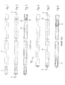
- a transport or bearing bushing 10 which is referred to as an inner tube 10 sheath tube 12 and these closing plugs 14, 16, which are also referred to as the first closure elements.
- the cladding tube 12 For filling the cladding tube 12 with a fuel rod, the cladding tube 12 is vertically aligned, wherein the stopper 16 shown on the right in the drawing extends on the bottom side.
- the cladding tube 12 with the lower stopper 16 is inserted into an outer tube 18, which consists of several sections which are connected by flanges, as this in principle from the FIGS. 7 and 8 or 14 and 16 results.
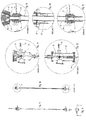
- a flange is exemplified by the reference numeral 26 (FIG. Fig. 20 ).
- the outer tube 18 projects endwise into a lower housing part 20 and an upper housing part 22, which have a cylinder geometry.
- the outer tube 18 is gas-tightly connected to the housing parts 20, 22 via vacuum flanges. Further, the outer tube 18 in its lower end portion designed as a bellows 25 section to compensate for changes in length, which may be caused by the fact that due to the temperature of the fuel rod, the envelope 12 referred to as the inner tube expands.
- the outer tube 18 and the housing parts 20, 22 thus form a receptacle for the inner or sheath tube 12th
- the cladding tube 12 with existing in this lower closure plug 16 is inserted at vertically aligned outer tube 18 via an existing in the upper housing part 22 funnel-shaped holder 24 (second receptacle), which is penetrated centrally by the longitudinal axis of the outer tube 18.
- the funnel-shaped holder 24 has a clear diameter that allows the cladding tube 12 and the inner tube, respectively, to be inserted.
- guides 28 extend from the inner wall of the outer tube 18, preferably adjacent to the flanges through which the sections of the outer tube 18 are joined together.
- the guides 28 each have a funnel-shaped geometry and consist in particular of stainless steel and are welded to the outer tube 18.
- the geometry of the guide 28 ensures that the inner tube or sheath tube 12 can be guided centrally through the outer tube 18 to a support 30 (first receptacle) present in the lower housing part 20.
- the support 30 has a cut in section conical recess with a seat 32 on which the cladding tube 12 is supported with the lower plug 16.
- the funnel-shaped guides 28 have recesses or grooves extending in the longitudinal direction, so that when the liquid is withdrawn it can flow through unhindered.
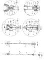
- the support 30 has a central bore 34 which is enforceable in the manner described below by a piston 36, via which the lower plug 16 axially within the cladding tube 12 is displaceable up to a stop 38, to then the plug 16 together with the cladding tube 12 to adjust axially within the outer tube 18 can.
- At least one fuel rod is introduced into the cladding tube 12, via the upper housing part 22, which can be closed by a cover 40 which is closed by a horizontally extending axis is pivotable.
- the upper closure plug 14 is inserted into the funnel-shaped holder, which has an upper peripheral flange-like edge 42, the diameter of which is greater than the lights Diameter of the funnel-shaped holder 24, so that the plug 14 is fixed by the holder 24.
- the upper housing part 22 is closed in a gas-tight manner via the cover 40 and the liquid present in the arrangement is drawn off. This can be done by introducing dry nitrogen so that the liquid is pushed out via an opening 46 in the bottom flange 44 of the lower housing part 20.
- the liquid can also be forced out of the inner tube, so the cladding tube 12 regardless of the fact that the lower plug 16 is in the cladding tube 12, the lower plug 16 has a plurality of outgoing from its inner end surface 48 holes in at least one radial Bore 50 pass, which in the Fig. 13 to be taken position of the plug 16 is aligned on existing in the peripheral wall of the cladding tube 12 recess 52, so that consequently the liquid can escape. Also in the upper region of the cladding tube 12 corresponding openings 54 are present.
- the piston 36 is displaced into the interior of the stopper 16 by the bore 34 provided in the seat 32 of the first receptacle 30 in order to displace the stopper 16 as far as the stop 38.
- the plug 16 is adjusted together with the cladding tube 12 in the direction of the upper plug 14 in a circumference that this penetrates into the cladding tube 12.
- the relevant positions are the FIGS. 19 and 21 refer to.
- the piston 36 is actuated via an adjustable in the lower housing part 20 linkage 58 which is adjustable within a cylinder 56 in which the piston 36 is arranged.
- the linkage 58 is sealed against the interior of the cylinder 56 via a bellows 60.
- induction coils 62, 64 which surround a hollow ceramic body 66, 68.
- the sealing plugs 14, 16 can then be materially bonded to the cladding tube 12.
- the temperature in the region of the connection is monitored.
- apertures 72, 74 are provided in the hollow ceramic bodies 66, 68 in order to be able to detect and regulate the temperature in the region of the material-bonding connection to be produced via an optic 76, 78.
- the temperature is transmitted via the optics to an optical fiber, not shown, which leads to an out-of-liquid measuring device such as pyrometers.
- the upper closure plug 14 in the cladding tube 12 during axial adjustment of this can not escape in the direction of the upper housing part 22, goes from the lid 14 to this pivotable bolt member 84, which prevents axial displacement of the plug 14.
- the closure plugs 14, 16 are properly bonded to the cladding tube 12, so the sleeve 10 is completed with the fuel rod spent in this, the upper housing part 22 is opened by pivoting the lid 40, so that liquid penetrates.
- the sleeve 10 is then pulled out of the arrangement, ie from the lower housing part 20, the outer tube 18 and the upper housing part 22 via the sectionally T-shaped projection 86 of the upper sealing plug 14.
- the outer tube 18 with the housing parts 20, 22 comprehensive arrangement is based on a support structure 88, which consists of composable profile sections.
Landscapes
- Physics & Mathematics (AREA)
- Engineering & Computer Science (AREA)
- General Engineering & Computer Science (AREA)
- High Energy & Nuclear Physics (AREA)
- Plasma & Fusion (AREA)
- Monitoring And Testing Of Nuclear Reactors (AREA)
- Application Of Or Painting With Fluid Materials (AREA)
Priority Applications (1)
| Application Number | Priority Date | Filing Date | Title |
|---|---|---|---|
| SI201130101T SI2418652T1 (sl) | 2010-07-13 | 2011-07-11 | Postopek in razmestitev za nepredušno oklepanje vsaj ene gorilne palice |
Applications Claiming Priority (1)
| Application Number | Priority Date | Filing Date | Title |
|---|---|---|---|
| DE102010036373A DE102010036373B3 (de) | 2010-07-13 | 2010-07-13 | Verfahren und Anordnung zum gasdichten Umschließen zumindest eines Brennstabs |
Publications (3)
| Publication Number | Publication Date |
|---|---|
| EP2418652A2 true EP2418652A2 (fr) | 2012-02-15 |
| EP2418652A3 EP2418652A3 (fr) | 2012-08-15 |
| EP2418652B1 EP2418652B1 (fr) | 2013-10-30 |
Family
ID=45098835
Family Applications (1)
| Application Number | Title | Priority Date | Filing Date |
|---|---|---|---|
| EP11173460.4A Active EP2418652B1 (fr) | 2010-07-13 | 2011-07-11 | Procédé et agencement destiné à entourer au moins une barre de combustible de manière étanche au gaz |
Country Status (4)
| Country | Link |
|---|---|
| EP (1) | EP2418652B1 (fr) |
| DE (1) | DE102010036373B3 (fr) |
| ES (1) | ES2441377T3 (fr) |
| SI (1) | SI2418652T1 (fr) |
Cited By (2)
| Publication number | Priority date | Publication date | Assignee | Title |
|---|---|---|---|---|
| CN105810272A (zh) * | 2012-03-02 | 2016-07-27 | 阿海珐有限公司 | 用于为中间储存封装燃料棒或燃料棒部分的方法和设备 |
| CN109990141A (zh) * | 2017-12-29 | 2019-07-09 | 核工业西南物理研究院 | 一种用于聚变堆大气侧的串联式带电水路贯穿件 |
Families Citing this family (2)
| Publication number | Priority date | Publication date | Assignee | Title |
|---|---|---|---|---|
| EP2807652B1 (fr) | 2012-01-26 | 2016-10-05 | AREVA GmbH | Dispositif et procédé pour encapsuler de manière étanche au gaz un barreau de combustible ou une partie de celle-ci |
| DE102012201131B3 (de) * | 2012-01-26 | 2013-03-28 | Areva Np Gmbh | Behälter, Vorrichtung und Verfahren zur gasdichten Kapselung eines Brennstabes oder eines Brennstababschnittes |
Citations (4)
| Publication number | Priority date | Publication date | Assignee | Title |
|---|---|---|---|---|
| DE2854358A1 (de) | 1977-12-16 | 1979-06-21 | Nl Industries Inc | Transportbehaelter fuer radioaktive materialien |
| DE8906938U1 (de) | 1989-06-06 | 1989-08-10 | Siemens AG, 1000 Berlin und 8000 München | Vorrichtung zum dichten Einbüchsen von Brennelementen im Brennelementbecken eines Kernkraftwerkes |
| US5633904A (en) | 1994-11-09 | 1997-05-27 | Newport News Shipbuilding And Dry Dock Company | Spent nuclear fuel (SNF) dry transfer system |
| DE19640393A1 (de) | 1996-09-30 | 1998-04-02 | Siemens Ag | Kapsel, Kernreaktorbrennelement mit einer Kapsel und Verfahren zum Herstellen einer Kapsel |
Family Cites Families (1)
| Publication number | Priority date | Publication date | Assignee | Title |
|---|---|---|---|---|
| DE102009003621B4 (de) * | 2009-01-23 | 2011-03-31 | Nuclear Cargo + Service Gmbh | Verfahren und Anordnung zum gasdichten Umschließen zumindest eines Brennstabs |
-
2010
- 2010-07-13 DE DE102010036373A patent/DE102010036373B3/de active Active
-
2011
- 2011-07-11 ES ES11173460.4T patent/ES2441377T3/es active Active
- 2011-07-11 EP EP11173460.4A patent/EP2418652B1/fr active Active
- 2011-07-11 SI SI201130101T patent/SI2418652T1/sl unknown
Patent Citations (4)
| Publication number | Priority date | Publication date | Assignee | Title |
|---|---|---|---|---|
| DE2854358A1 (de) | 1977-12-16 | 1979-06-21 | Nl Industries Inc | Transportbehaelter fuer radioaktive materialien |
| DE8906938U1 (de) | 1989-06-06 | 1989-08-10 | Siemens AG, 1000 Berlin und 8000 München | Vorrichtung zum dichten Einbüchsen von Brennelementen im Brennelementbecken eines Kernkraftwerkes |
| US5633904A (en) | 1994-11-09 | 1997-05-27 | Newport News Shipbuilding And Dry Dock Company | Spent nuclear fuel (SNF) dry transfer system |
| DE19640393A1 (de) | 1996-09-30 | 1998-04-02 | Siemens Ag | Kapsel, Kernreaktorbrennelement mit einer Kapsel und Verfahren zum Herstellen einer Kapsel |
Cited By (3)
| Publication number | Priority date | Publication date | Assignee | Title |
|---|---|---|---|---|
| CN105810272A (zh) * | 2012-03-02 | 2016-07-27 | 阿海珐有限公司 | 用于为中间储存封装燃料棒或燃料棒部分的方法和设备 |
| CN109990141A (zh) * | 2017-12-29 | 2019-07-09 | 核工业西南物理研究院 | 一种用于聚变堆大气侧的串联式带电水路贯穿件 |
| CN109990141B (zh) * | 2017-12-29 | 2023-12-26 | 核工业西南物理研究院 | 一种用于聚变堆大气侧的串联式带电水路贯穿件 |
Also Published As
| Publication number | Publication date |
|---|---|
| EP2418652B1 (fr) | 2013-10-30 |
| EP2418652A3 (fr) | 2012-08-15 |
| ES2441377T3 (es) | 2014-02-04 |
| DE102010036373B3 (de) | 2012-01-05 |
| SI2418652T1 (sl) | 2014-02-28 |
Similar Documents
| Publication | Publication Date | Title |
|---|---|---|
| DE2854358A1 (de) | Transportbehaelter fuer radioaktive materialien | |
| DE2915376C2 (de) | Behälterkombination für den Transport und die Lagerung bestrahlter Brennelemente aus Kernreaktoren | |
| EP2389675B1 (fr) | Procédé et dispositif permettant d'entourer de manière étanche au gaz au moins une barre de combustible | |
| DE3138485C2 (de) | Behälter zur Aufnahme und Aufbewahrung von radioaktiven Stoffen | |
| EP2418652B1 (fr) | Procédé et agencement destiné à entourer au moins une barre de combustible de manière étanche au gaz | |
| DE2124530C3 (de) | Einrichtung zum Verschließen schadhafter Wärmetauseherrohre | |
| DE2441999A1 (de) | Verfahren zur staendigen kontrolle des zweischalen-reaktorgefaesses eines reaktors und reaktor zur anwendung dieses verfahrens | |
| DE2737532C2 (de) | Verfahren zum Schutz der Hüllrohre von Kernreaktorbrennstäben | |
| CH689240A5 (de) | Kernrohr- und Tragplattenbaueinheit fuer Druckwasserkernreaktor. | |
| DE10116627A1 (de) | Verschlußstopfen für ein zur Aufnahme eines Brennstabes bestimmtes Kapselrohr sowie Kapsel für einen Kernbrennstab | |
| DE2812124A1 (de) | Kernenergieanlage in loop-anordnung | |
| DE1236090B (de) | Kernspaltstoffstab | |
| EP1600982B1 (fr) | Récipient et procédé pour l'enveloppement imperméable aux gaz d'un objet radioactive | |
| DE2728604C2 (de) | Vorrichtung zur Durchführung von elektrischen Leitungen durch eine Deckplatte des Reaktorgefäßes eines Kernreaktors | |
| DE2535355A1 (de) | Verschlussanordnung in einem gasgekuehlten kernreaktorsystem | |
| EP2824669B1 (fr) | Logement pour crayon combustible | |
| EP2824668B1 (fr) | Procédé de séchage d'un crayon combustible logé dans un logement pour crayon combustible | |
| DE102012212006A1 (de) | Verfahren und Vorrichtung zur Kapselung eines Brennstabes oder eines Brennstababschnittes für eine Zwischenlagerung | |
| DE1600551A1 (de) | Abgedichtete Verschlussanordnung,insbesondere fuer Seekabelverstaerkergehaeuse | |
| DE1489950B1 (de) | Notkondensationsanlage fuer dampfgekuehlte Kernreaktoren | |
| DE2508349A1 (de) | Schutzvorrichtung gegen lecks eines druckgefaess-reaktors | |
| DE4314708A1 (de) | Brennstab mit vorbestimmtem Sekundärschaden | |
| DE3339627C2 (de) | Reaktordruckbehälter einer wassergekühlten Kernreaktoranlage | |
| DE2149718A1 (de) | Bestrahlungskapsel mit veraenderlichem Energiespektrum fuer Kernreaktoren | |
| EP0978849A1 (fr) | Conteneur pour le stockage définitif d'éléments combustibles épuisés de centrales nucléaires |
Legal Events
| Date | Code | Title | Description |
|---|---|---|---|
| AK | Designated contracting states |
Kind code of ref document: A2 Designated state(s): AL AT BE BG CH CY CZ DE DK EE ES FI FR GB GR HR HU IE IS IT LI LT LU LV MC MK MT NL NO PL PT RO RS SE SI SK SM TR |
|
| AX | Request for extension of the european patent |
Extension state: BA ME |
|
| PUAI | Public reference made under article 153(3) epc to a published international application that has entered the european phase |
Free format text: ORIGINAL CODE: 0009012 |
|
| PUAL | Search report despatched |
Free format text: ORIGINAL CODE: 0009013 |
|
| AK | Designated contracting states |
Kind code of ref document: A3 Designated state(s): AL AT BE BG CH CY CZ DE DK EE ES FI FR GB GR HR HU IE IS IT LI LT LU LV MC MK MT NL NO PL PT RO RS SE SI SK SM TR |
|
| AX | Request for extension of the european patent |
Extension state: BA ME |
|
| RIC1 | Information provided on ipc code assigned before grant |
Ipc: G21F 9/28 20060101ALI20120712BHEP Ipc: G21F 5/008 20060101ALI20120712BHEP Ipc: G21C 19/32 20060101AFI20120712BHEP |
|
| 17P | Request for examination filed |
Effective date: 20120809 |
|
| GRAP | Despatch of communication of intention to grant a patent |
Free format text: ORIGINAL CODE: EPIDOSNIGR1 |
|
| INTG | Intention to grant announced |
Effective date: 20130325 |
|
| GRAS | Grant fee paid |
Free format text: ORIGINAL CODE: EPIDOSNIGR3 |
|
| GRAP | Despatch of communication of intention to grant a patent |
Free format text: ORIGINAL CODE: EPIDOSNIGR1 |
|
| GRAA | (expected) grant |
Free format text: ORIGINAL CODE: 0009210 |
|
| INTG | Intention to grant announced |
Effective date: 20130912 |
|
| AK | Designated contracting states |
Kind code of ref document: B1 Designated state(s): AL AT BE BG CH CY CZ DE DK EE ES FI FR GB GR HR HU IE IS IT LI LT LU LV MC MK MT NL NO PL PT RO RS SE SI SK SM TR |
|
| REG | Reference to a national code |
Ref country code: GB Ref legal event code: FG4D Free format text: NOT ENGLISH |
|
| REG | Reference to a national code |
Ref country code: CH Ref legal event code: EP |
|
| REG | Reference to a national code |
Ref country code: AT Ref legal event code: REF Ref document number: 638679 Country of ref document: AT Kind code of ref document: T Effective date: 20131115 |
|
| REG | Reference to a national code |
Ref country code: IE Ref legal event code: FG4D Free format text: LANGUAGE OF EP DOCUMENT: GERMAN |
|
| REG | Reference to a national code |
Ref country code: CH Ref legal event code: NV Representative=s name: LUCHS AND PARTNER PATENTANWAELTE, CH |
|
| REG | Reference to a national code |
Ref country code: DE Ref legal event code: R096 Ref document number: 502011001551 Country of ref document: DE Effective date: 20131224 |
|
| REG | Reference to a national code |
Ref country code: NL Ref legal event code: T3 |
|
| REG | Reference to a national code |
Ref country code: RO Ref legal event code: EPE |
|
| REG | Reference to a national code |
Ref country code: SE Ref legal event code: TRGR Ref country code: ES Ref legal event code: FG2A Ref document number: 2441377 Country of ref document: ES Kind code of ref document: T3 Effective date: 20140204 |
|
| REG | Reference to a national code |
Ref country code: LT Ref legal event code: MG4D |
|
| PG25 | Lapsed in a contracting state [announced via postgrant information from national office to epo] |
Ref country code: LT Free format text: LAPSE BECAUSE OF FAILURE TO SUBMIT A TRANSLATION OF THE DESCRIPTION OR TO PAY THE FEE WITHIN THE PRESCRIBED TIME-LIMIT Effective date: 20131030 Ref country code: HR Free format text: LAPSE BECAUSE OF FAILURE TO SUBMIT A TRANSLATION OF THE DESCRIPTION OR TO PAY THE FEE WITHIN THE PRESCRIBED TIME-LIMIT Effective date: 20131030 Ref country code: NO Free format text: LAPSE BECAUSE OF FAILURE TO SUBMIT A TRANSLATION OF THE DESCRIPTION OR TO PAY THE FEE WITHIN THE PRESCRIBED TIME-LIMIT Effective date: 20140130 Ref country code: IS Free format text: LAPSE BECAUSE OF FAILURE TO SUBMIT A TRANSLATION OF THE DESCRIPTION OR TO PAY THE FEE WITHIN THE PRESCRIBED TIME-LIMIT Effective date: 20140228 |
|
| REG | Reference to a national code |
Ref country code: SK Ref legal event code: T3 Ref document number: E 15732 Country of ref document: SK |
|
| PG25 | Lapsed in a contracting state [announced via postgrant information from national office to epo] |
Ref country code: RS Free format text: LAPSE BECAUSE OF FAILURE TO SUBMIT A TRANSLATION OF THE DESCRIPTION OR TO PAY THE FEE WITHIN THE PRESCRIBED TIME-LIMIT Effective date: 20131030 Ref country code: LV Free format text: LAPSE BECAUSE OF FAILURE TO SUBMIT A TRANSLATION OF THE DESCRIPTION OR TO PAY THE FEE WITHIN THE PRESCRIBED TIME-LIMIT Effective date: 20131030 Ref country code: CY Free format text: LAPSE BECAUSE OF FAILURE TO SUBMIT A TRANSLATION OF THE DESCRIPTION OR TO PAY THE FEE WITHIN THE PRESCRIBED TIME-LIMIT Effective date: 20131030 |
|
| PG25 | Lapsed in a contracting state [announced via postgrant information from national office to epo] |
Ref country code: PT Free format text: LAPSE BECAUSE OF FAILURE TO SUBMIT A TRANSLATION OF THE DESCRIPTION OR TO PAY THE FEE WITHIN THE PRESCRIBED TIME-LIMIT Effective date: 20140228 |
|
| REG | Reference to a national code |
Ref country code: HU Ref legal event code: AG4A Ref document number: E019215 Country of ref document: HU |
|
| PG25 | Lapsed in a contracting state [announced via postgrant information from national office to epo] |
Ref country code: EE Free format text: LAPSE BECAUSE OF FAILURE TO SUBMIT A TRANSLATION OF THE DESCRIPTION OR TO PAY THE FEE WITHIN THE PRESCRIBED TIME-LIMIT Effective date: 20131030 |
|
| REG | Reference to a national code |
Ref country code: DE Ref legal event code: R097 Ref document number: 502011001551 Country of ref document: DE |
|
| PG25 | Lapsed in a contracting state [announced via postgrant information from national office to epo] |
Ref country code: CZ Free format text: LAPSE BECAUSE OF FAILURE TO SUBMIT A TRANSLATION OF THE DESCRIPTION OR TO PAY THE FEE WITHIN THE PRESCRIBED TIME-LIMIT Effective date: 20131030 Ref country code: PL Free format text: LAPSE BECAUSE OF FAILURE TO SUBMIT A TRANSLATION OF THE DESCRIPTION OR TO PAY THE FEE WITHIN THE PRESCRIBED TIME-LIMIT Effective date: 20131030 |
|
| PLBE | No opposition filed within time limit |
Free format text: ORIGINAL CODE: 0009261 |
|
| STAA | Information on the status of an ep patent application or granted ep patent |
Free format text: STATUS: NO OPPOSITION FILED WITHIN TIME LIMIT |
|
| PG25 | Lapsed in a contracting state [announced via postgrant information from national office to epo] |
Ref country code: DK Free format text: LAPSE BECAUSE OF FAILURE TO SUBMIT A TRANSLATION OF THE DESCRIPTION OR TO PAY THE FEE WITHIN THE PRESCRIBED TIME-LIMIT Effective date: 20131030 |
|
| 26N | No opposition filed |
Effective date: 20140731 |
|
| REG | Reference to a national code |
Ref country code: DE Ref legal event code: R097 Ref document number: 502011001551 Country of ref document: DE Effective date: 20140731 |
|
| PG25 | Lapsed in a contracting state [announced via postgrant information from national office to epo] |
Ref country code: LU Free format text: LAPSE BECAUSE OF FAILURE TO SUBMIT A TRANSLATION OF THE DESCRIPTION OR TO PAY THE FEE WITHIN THE PRESCRIBED TIME-LIMIT Effective date: 20140711 |
|
| REG | Reference to a national code |
Ref country code: IE Ref legal event code: MM4A |
|
| PG25 | Lapsed in a contracting state [announced via postgrant information from national office to epo] |
Ref country code: IE Free format text: LAPSE BECAUSE OF NON-PAYMENT OF DUE FEES Effective date: 20140711 |
|
| PG25 | Lapsed in a contracting state [announced via postgrant information from national office to epo] |
Ref country code: SM Free format text: LAPSE BECAUSE OF FAILURE TO SUBMIT A TRANSLATION OF THE DESCRIPTION OR TO PAY THE FEE WITHIN THE PRESCRIBED TIME-LIMIT Effective date: 20131030 Ref country code: MC Free format text: LAPSE BECAUSE OF FAILURE TO SUBMIT A TRANSLATION OF THE DESCRIPTION OR TO PAY THE FEE WITHIN THE PRESCRIBED TIME-LIMIT Effective date: 20131030 |
|
| PG25 | Lapsed in a contracting state [announced via postgrant information from national office to epo] |
Ref country code: GR Free format text: LAPSE BECAUSE OF FAILURE TO SUBMIT A TRANSLATION OF THE DESCRIPTION OR TO PAY THE FEE WITHIN THE PRESCRIBED TIME-LIMIT Effective date: 20140131 Ref country code: MT Free format text: LAPSE BECAUSE OF FAILURE TO SUBMIT A TRANSLATION OF THE DESCRIPTION OR TO PAY THE FEE WITHIN THE PRESCRIBED TIME-LIMIT Effective date: 20131030 |
|
| REG | Reference to a national code |
Ref country code: FR Ref legal event code: PLFP Year of fee payment: 6 |
|
| PG25 | Lapsed in a contracting state [announced via postgrant information from national office to epo] |
Ref country code: TR Free format text: LAPSE BECAUSE OF FAILURE TO SUBMIT A TRANSLATION OF THE DESCRIPTION OR TO PAY THE FEE WITHIN THE PRESCRIBED TIME-LIMIT Effective date: 20131030 |
|
| REG | Reference to a national code |
Ref country code: CH Ref legal event code: PFA Owner name: DAHER NUCLEAR TECHNOLOGIES GMBH, DE Free format text: FORMER OWNER: NUCLEAR CARGO + SERVICE GMBH, DE Ref country code: CH Ref legal event code: NV Representative=s name: LUCHS AND PARTNER AG PATENTANWAELTE, CH |
|
| REG | Reference to a national code |
Ref country code: NL Ref legal event code: PD Owner name: DAHER NUCLEAR TECHNOLOGIES GMBH; DE Free format text: DETAILS ASSIGNMENT: VERANDERING VAN EIGENAAR(S), OVERDRACHT; FORMER OWNER NAME: NUCLEAR CARGO + SERVICE GMBH Effective date: 20160816 |
|
| REG | Reference to a national code |
Ref country code: HU Ref legal event code: HC9C Owner name: DAHER NUCLEAR TECHNOLOGIES GMBH, DE Free format text: FORMER OWNER(S): NUCLEAR CARGO + SERVICE GMBH, DE |
|
| REG | Reference to a national code |
Ref country code: SI Ref legal event code: SP73 Owner name: DAHER NUCLEAR TECHNOLOGIES GMBH; DE Effective date: 20161003 |
|
| REG | Reference to a national code |
Ref country code: SK Ref legal event code: TC4A Ref document number: E 15732 Country of ref document: SK Owner name: DAHER NUCLEAR TECHNOLOGIES GMBH, HANAU, DE Effective date: 20161128 |
|
| REG | Reference to a national code |
Ref country code: FR Ref legal event code: CD Owner name: DAHER NUCLEAR TECHNOLOGIES GMBH, DE Effective date: 20170223 |
|
| REG | Reference to a national code |
Ref country code: ES Ref legal event code: PC2A Owner name: DAHER NUCLEAR TECHNOLOGIES GMBH Effective date: 20170412 |
|
| REG | Reference to a national code |
Ref country code: FR Ref legal event code: PLFP Year of fee payment: 7 |
|
| PGFP | Annual fee paid to national office [announced via postgrant information from national office to epo] |
Ref country code: RO Payment date: 20170628 Year of fee payment: 7 |
|
| REG | Reference to a national code |
Ref country code: AT Ref legal event code: MM01 Ref document number: 638679 Country of ref document: AT Kind code of ref document: T Effective date: 20160711 |
|
| PG25 | Lapsed in a contracting state [announced via postgrant information from national office to epo] |
Ref country code: AT Free format text: LAPSE BECAUSE OF NON-PAYMENT OF DUE FEES Effective date: 20160711 |
|
| PGFP | Annual fee paid to national office [announced via postgrant information from national office to epo] |
Ref country code: HU Payment date: 20170719 Year of fee payment: 7 Ref country code: BG Payment date: 20170726 Year of fee payment: 7 |
|
| PG25 | Lapsed in a contracting state [announced via postgrant information from national office to epo] |
Ref country code: MK Free format text: LAPSE BECAUSE OF FAILURE TO SUBMIT A TRANSLATION OF THE DESCRIPTION OR TO PAY THE FEE WITHIN THE PRESCRIBED TIME-LIMIT Effective date: 20131030 |
|
| REG | Reference to a national code |
Ref country code: FR Ref legal event code: PLFP Year of fee payment: 8 |
|
| PG25 | Lapsed in a contracting state [announced via postgrant information from national office to epo] |
Ref country code: AL Free format text: LAPSE BECAUSE OF FAILURE TO SUBMIT A TRANSLATION OF THE DESCRIPTION OR TO PAY THE FEE WITHIN THE PRESCRIBED TIME-LIMIT Effective date: 20131030 |
|
| PG25 | Lapsed in a contracting state [announced via postgrant information from national office to epo] |
Ref country code: HU Free format text: LAPSE BECAUSE OF NON-PAYMENT OF DUE FEES Effective date: 20180712 Ref country code: RO Free format text: LAPSE BECAUSE OF NON-PAYMENT OF DUE FEES Effective date: 20180711 |
|
| PG25 | Lapsed in a contracting state [announced via postgrant information from national office to epo] |
Ref country code: BG Free format text: LAPSE BECAUSE OF NON-PAYMENT OF DUE FEES Effective date: 20190430 |
|
| PGFP | Annual fee paid to national office [announced via postgrant information from national office to epo] |
Ref country code: GB Payment date: 20250515 Year of fee payment: 15 |
|
| PGFP | Annual fee paid to national office [announced via postgrant information from national office to epo] |
Ref country code: SI Payment date: 20250703 Year of fee payment: 15 |
|
| PGFP | Annual fee paid to national office [announced via postgrant information from national office to epo] |
Ref country code: NL Payment date: 20250721 Year of fee payment: 15 |
|
| PGFP | Annual fee paid to national office [announced via postgrant information from national office to epo] |
Ref country code: ES Payment date: 20250826 Year of fee payment: 15 Ref country code: FI Payment date: 20250725 Year of fee payment: 15 |
|
| PGFP | Annual fee paid to national office [announced via postgrant information from national office to epo] |
Ref country code: DE Payment date: 20250722 Year of fee payment: 15 |
|
| PGFP | Annual fee paid to national office [announced via postgrant information from national office to epo] |
Ref country code: IT Payment date: 20250724 Year of fee payment: 15 |
|
| PGFP | Annual fee paid to national office [announced via postgrant information from national office to epo] |
Ref country code: BE Payment date: 20250718 Year of fee payment: 15 |
|
| PGFP | Annual fee paid to national office [announced via postgrant information from national office to epo] |
Ref country code: FR Payment date: 20250725 Year of fee payment: 15 |
|
| PGFP | Annual fee paid to national office [announced via postgrant information from national office to epo] |
Ref country code: CH Payment date: 20250801 Year of fee payment: 15 Ref country code: SE Payment date: 20250722 Year of fee payment: 15 |
|
| PGFP | Annual fee paid to national office [announced via postgrant information from national office to epo] |
Ref country code: SK Payment date: 20250708 Year of fee payment: 15 |