EP2418749A1 - Dispositif d'alimentation électrique et système de commande d'alimentation électrique - Google Patents
Dispositif d'alimentation électrique et système de commande d'alimentation électrique Download PDFInfo
- Publication number
- EP2418749A1 EP2418749A1 EP10761780A EP10761780A EP2418749A1 EP 2418749 A1 EP2418749 A1 EP 2418749A1 EP 10761780 A EP10761780 A EP 10761780A EP 10761780 A EP10761780 A EP 10761780A EP 2418749 A1 EP2418749 A1 EP 2418749A1
- Authority
- EP
- European Patent Office
- Prior art keywords
- electric power
- information
- manager
- storage
- storage system
- Prior art date
- Legal status (The legal status is an assumption and is not a legal conclusion. Google has not performed a legal analysis and makes no representation as to the accuracy of the status listed.)
- Withdrawn
Links
Images






Classifications
-
- G—PHYSICS
- G05—CONTROLLING; REGULATING
- G05B—CONTROL OR REGULATING SYSTEMS IN GENERAL; FUNCTIONAL ELEMENTS OF SUCH SYSTEMS; MONITORING OR TESTING ARRANGEMENTS FOR SUCH SYSTEMS OR ELEMENTS
- G05B15/00—Systems controlled by a computer
- G05B15/02—Systems controlled by a computer electric
-
- G—PHYSICS
- G05—CONTROLLING; REGULATING
- G05F—SYSTEMS FOR REGULATING ELECTRIC OR MAGNETIC VARIABLES
- G05F1/00—Automatic systems in which deviations of an electric quantity from one or more predetermined values are detected at the output of the system and fed back to a device within the system to restore the detected quantity to its predetermined value or values, i.e. retroactive systems
- G05F1/66—Regulating electric power
-
- H—ELECTRICITY
- H01—ELECTRIC ELEMENTS
- H01M—PROCESSES OR MEANS, e.g. BATTERIES, FOR THE DIRECT CONVERSION OF CHEMICAL ENERGY INTO ELECTRICAL ENERGY
- H01M10/00—Secondary cells; Manufacture thereof
- H01M10/42—Methods or arrangements for servicing or maintenance of secondary cells or secondary half-cells
- H01M10/425—Structural combination with electronic components, e.g. electronic circuits integrated to the outside of the casing
-
- H—ELECTRICITY
- H02—GENERATION; CONVERSION OR DISTRIBUTION OF ELECTRIC POWER
- H02J—ELECTRIC POWER NETWORKS; CIRCUIT ARRANGEMENTS OR SYSTEMS FOR SUPPLYING OR DISTRIBUTING ELECTRIC POWER; SYSTEMS FOR STORING ELECTRIC ENERGY
- H02J3/00—Circuit arrangements for AC mains or AC distribution networks
- H02J3/28—Arrangements for balancing of the load in networks by storage of energy
- H02J3/32—Arrangements for balancing of the load in networks by storage of energy using batteries or super capacitors with converting means
-
- H—ELECTRICITY
- H02—GENERATION; CONVERSION OR DISTRIBUTION OF ELECTRIC POWER
- H02J—ELECTRIC POWER NETWORKS; CIRCUIT ARRANGEMENTS OR SYSTEMS FOR SUPPLYING OR DISTRIBUTING ELECTRIC POWER; SYSTEMS FOR STORING ELECTRIC ENERGY
- H02J3/00—Circuit arrangements for AC mains or AC distribution networks
- H02J3/38—Arrangements for feeding a single network from two or more generators or sources in parallel; Arrangements for feeding already energised networks from additional generators or sources in parallel
- H02J3/381—Dispersed generators
-
- H—ELECTRICITY
- H02—GENERATION; CONVERSION OR DISTRIBUTION OF ELECTRIC POWER
- H02J—ELECTRIC POWER NETWORKS; CIRCUIT ARRANGEMENTS OR SYSTEMS FOR SUPPLYING OR DISTRIBUTING ELECTRIC POWER; SYSTEMS FOR STORING ELECTRIC ENERGY
- H02J7/00—Circuit arrangements for charging or discharging batteries or for supplying loads from batteries
- H02J7/34—Parallel operation in networks using both storage and other DC sources, e.g. providing buffering
-
- H—ELECTRICITY
- H02—GENERATION; CONVERSION OR DISTRIBUTION OF ELECTRIC POWER
- H02J—ELECTRIC POWER NETWORKS; CIRCUIT ARRANGEMENTS OR SYSTEMS FOR SUPPLYING OR DISTRIBUTING ELECTRIC POWER; SYSTEMS FOR STORING ELECTRIC ENERGY
- H02J7/00—Circuit arrangements for charging or discharging batteries or for supplying loads from batteries
- H02J7/34—Parallel operation in networks using both storage and other DC sources, e.g. providing buffering
- H02J7/35—Parallel operation in networks using both storage and other DC sources, e.g. providing buffering with light sensitive cells
-
- Y—GENERAL TAGGING OF NEW TECHNOLOGICAL DEVELOPMENTS; GENERAL TAGGING OF CROSS-SECTIONAL TECHNOLOGIES SPANNING OVER SEVERAL SECTIONS OF THE IPC; TECHNICAL SUBJECTS COVERED BY FORMER USPC CROSS-REFERENCE ART COLLECTIONS [XRACs] AND DIGESTS
- Y02—TECHNOLOGIES OR APPLICATIONS FOR MITIGATION OR ADAPTATION AGAINST CLIMATE CHANGE
- Y02E—REDUCTION OF GREENHOUSE GAS [GHG] EMISSIONS, RELATED TO ENERGY GENERATION, TRANSMISSION OR DISTRIBUTION
- Y02E60/00—Enabling technologies; Technologies with a potential or indirect contribution to GHG emissions mitigation
- Y02E60/10—Energy storage using batteries
-
- Y—GENERAL TAGGING OF NEW TECHNOLOGICAL DEVELOPMENTS; GENERAL TAGGING OF CROSS-SECTIONAL TECHNOLOGIES SPANNING OVER SEVERAL SECTIONS OF THE IPC; TECHNICAL SUBJECTS COVERED BY FORMER USPC CROSS-REFERENCE ART COLLECTIONS [XRACs] AND DIGESTS
- Y02—TECHNOLOGIES OR APPLICATIONS FOR MITIGATION OR ADAPTATION AGAINST CLIMATE CHANGE
- Y02E—REDUCTION OF GREENHOUSE GAS [GHG] EMISSIONS, RELATED TO ENERGY GENERATION, TRANSMISSION OR DISTRIBUTION
- Y02E70/00—Other energy conversion or management systems reducing GHG emissions
- Y02E70/30—Systems combining energy storage with energy generation of non-fossil origin
Definitions
- the present invention relates to an electric power device and an electric power control system which can be applied to an electric storage device in the home and the like.
- an object of the present invention is to provide an electric power device and an electric power control system, in which a home storage is configured by an energy device such as a battery which can be used for a single application or a plurality of applications, so that the cost for introducing the battery and the home storage is significantly reduced.
- the present invention provides an electric power device including: an energy device; a device manager; and a storage system manager.
- the energy device includes an ID, and the storage system manager performs a mutual authentication using the ID.
- the device manager receives the storage information from or transmits the storage information to the storage system manager via an information bus.
- the device manager or the storage system manager receives the storage information from or transmits the storage information to a home controller which controls a home electric power.
- the storage system manager and the home controller perform a mutual authentication.
- the device manager or the storage system manager receives the storage information from or transmits the storage information to a server on a network.
- the device manager or the storage system manager receives the storage information from or transmits the storage information to an electric power conditioner.
- the device manager, the storage system manager or the home controller acquires storage control information from the server on a network.
- the device manager, the storage system manager or the home controller controls the energy device according to the storage control information.
- the present invention provides an electric power device including: a storage system manager; a first electric power module which includes a first energy device and a first device manager; and a second electric power module which includes a second energy device and a second device manager.
- the present invention provides an electric power control system including: an electric power device which includes an energy device, a device manager, and a storage system manager; a home controller; and an electric power conditioner.
- the device manager or the storage system manager receives the storage information from or transmits the storage information to the network, the home controller, or the electric power conditioner.
- the home controller, the storage system manager, or the device manager controls the electric power conditioner according to storage information for controlling electric power to be supplied to the electric power device.
- the home controller, the device manager, or the electric power conditioner monitors a power consumption amount, and acquires information on the power consumption amount.
- the home controller, the storage system manager, the device manager, or the electric power conditioner performs control of supplying electric power of the electric power device or supplying electric power to the electric power storage means according to information on the power consumption amount.
- the home controller, the storage system manager, the device manager, or the electric power conditioner performs control of increasing or starting the supplying of the electric power to the electric power device or the electric power storage means when the power consumption amount is small, and/or performs control of increasing or starting the supplying of the electric power from the electric power device or the electric power storage means when the power consumption amount is large.
- the home controller, the storage system manager, the device manager, or the electric power conditioner performs optimal control of supplying the electric power from an electric power supply grid according to the power consumption amount.
- the home controller, the storage system manager, the device manager, or the electric power conditioner performs control of reducing or stopping the supplying of the electric power from an electric power supply grid when the power consumption amount is large, and/or performs control of increasing or starting the supplying of the electric power to an electric power supply grid when the power consumption amount is small.
- the home controller, the storage system manager, the device manager, or the electric power conditioner performs control of supplying electric power to the electric power device according to information which is supplied from a server on a network.
- the home controller, the storage system manager, the device manager, or the electric power conditioner performs control of supplying the electric power to the electric power device or electric power storage means, and/or performs control of supplying the electric power from the electric power device or the electric power storage means according to the detected information.
- the home controller, the storage system manager, the device manager, or the electric power conditioner performs control of supplying the electric power to an electric power supply grid, and/or performs control of supplying the electric power from the electric power supply grid according to the detected information.
- the home controller, the storage system manager, the device manager, or the electric power conditioner predicts the power consumption amount according to the detected information or the supplied information.
- the home controller, the storage system manager, the device manager, or the electric power conditioner performs control of supplying the electric power to the electric power device according to the predicted power consumption amount.
- a mutual authentication is performed between at least two of the energy device, the device manager, the storage system manager, the home controller, the electric power conditioner, and the network.
- an I/O of an energy device such as a battery used for a storage, an interface for charging, and an authentication scheme are standardized (commonalized), and the device is managed via a network, so that the energy device can be used safely.
- the energy device can be used for many other applications. As a result, the energy device is reduced in cost, and new applications driven with a battery may continue to increase, and furthermore the convenience of the energy device management is improved for the user.
- such a standardized device is utilized as a home storage. Therefore, there is no need to make a large initial investment, the capacity or the configuration of the storage can be flexibly improved according to customer's intention, and furthermore, effective use of the batteries for various kinds of applications, resource saving, and space saving are promoted.
- the electric power control system is characterized by providing: electric power, security, and user services for comfort at home; operating on a common platform; and being connected between sensors, electric power devices according to the present invention (referred to as a smart storage), homes, and communities.
- a smart storage the electric power storage can be solved as described below. Furthermore, output of clean energy such as photovoltaic power generation, fuel cells, and wind power generation is supplied to the home.
- the electric power control system includes an energy device, an electric power device which has a device manager and a storage system manager, a home controller, and an electric power conditioning device (hereinafter, suitably referred to as an electric power conditioner). Furthermore, the system includes a network.
- the network includes an electric power company, an energy service provider, a communication service provider, a storage supplier, a personal digital assistant, a mobile computer, and a composition thereof.
- the outline of an example of software architecture of the smart storage is shown in Fig. 2 .
- the device manager is the software which performs control closest to the battery as the energy device.
- the device manager monitors the state, safety, and reliability of each device.
- the storage system manager relates to the device manager.
- the storage system manager monitors system operations, optimization of load sharing, status, safety, and reliability of the system.
- the storage system manager relates to the home energy manager via an API (Application Programming Interface). Furthermore, the storage system manager exchanges information with a server on the network, via the network. The home energy manager exchanges information with the server on the network, via the network.
- API Application Programming Interface
- the home energy manager monitors the storage and controls operations of the storage. In this case, manufacturing information, maintenance information, and trouble information of devices are exchanged with the server on the network.
- an energy service provider or a storage service provider controls the storage monitoring and operations of the storage system manager.
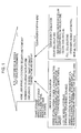
- information as shown in Fig. 3 is used.
- information of sensors is used.
- information of household sensors is used. Specifically, information such as monitoring operations of motion sensors, sensors for doors/windows/keys, noise sensors, switch ON/OFF, electronic apparatuses, and household electric appliances are used. Furthermore, information on individual schedules, individual information of the user, and a combination thereof are used.
- information of the household sensors is used. Specifically, information of a temperature sensor and a humidity sensor, a vibration sensor, an air monitoring sensor, a brightness sensor and the like is used.
- climate of a mesh for example, 50m x 50m
- weather information of local regions are used.
- the sensors monitor temperature, humidity, brightness, human activities indoors or outdoors, or a combination thereof.
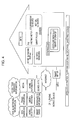
- a home network hub At home, a home network hub, sensors, the smart storage, a controller of the smart storage, electronic apparatuses equipped with the sensors, and a photovoltaic power generator (for example, BIPV (Building Integrated Photovoltaic Module)) are arranged. All of these are connected to a grid through a smart meter. Furthermore, it is possible that external information may be brought into the home via the Internet.
- a photovoltaic power generator for example, BIPV (Building Integrated Photovoltaic Module)
- a peak shift of the electric power becomes possible.
- Fig. 6 shows the outline of the peak shift.
- the peaks of the power consumption can be suppressed as shown by a solid line.
- the electric power accumulated in the smart storage is generated using renewable energy, carbon dioxide emissions at home can be suppressed.
- the conventional household battery has been used for assisting only the household power consumption, and it has a large size and is expensive.
- the battery can be used both as the household battery and another type of battery, for example, a power supply for an electric bicycle, so that the problems in the related art are solved.
- the battery communicates with a home energy gateway.
- the home energy gateway charges the battery, and causes the battery to function as the household battery.
- the home energy gateway is connected to a battery management server via a network, for example, the Internet.
- the battery can be uniquely identified by a secure battery identifier (battery ID).
- the battery management server manages each battery using the battery ID.
- a database of information required for using the battery which is specified by the battery ID is established in the battery management server.
- the home energy gateway receives storage information corresponding to the battery ID from the server, so that the battery can be charged safely and appropriately. Furthermore, information on the use results of the battery (the number of times charged, trouble, etc.) is sent from the home energy gateway to the server, and the storage information stored in the database of the server is updated with the latest information.
- the battery is configured to be detachable, and it is used for another purpose after detaching.
- the battery is used as electric equipment, for example, an electric power source of the electric bicycle.
- the use of the battery is not limited to the electric car, but an electric motorcycle, an electric bicycle, a battery type home appliance, battery type commercial equipment, a battery type computer, battery type portable equipment, various kinds of battery devices, and a combination thereof may also use the battery.
- the battery is applicable as an electric power source other than the household battery, and a controlling and charging device is provided in common over a plurality of types of batteries. Therefore, without damaging safety, the household battery can be configured at a low cost. Furthermore, if the battery is charged by the electric power which is generated by using the renewable energy at home, the carbon dioxide emissions can be reduced.
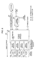
- Fig. 8 shows a specific configuration of the smart storage 200 according to the present invention.
- four batteries 107a, 107b, 107c, and 107d are controlled by device managers 201a, 201b, 201c, and 201d, respectively.
- the number of batteries is an example, and up to N batteries can be connected.
- the reference numerals of "107" and "201" are used to represent each of them.
- the device manager 201 includes a plurality of sockets as a physical connection unit.
- the batteries 107 are inserted to the sockets, respectively.
- Different types of the battery 107 may be used.
- a lithium-ion battery, a capacitor, a fuel cell, a micro generator and the like can be used. Even though the types of batteries are different, all of the batteries 107 can be inserted into standardized sockets.
- the socket holds the battery 107 physically and secures an interface between the battery 107 and the device manager 201.
- the interface necessitates at least positive/negative power terminals and an output terminal for the battery ID.
- a terminal for taking out a temperature detection output in the battery 107 may be provided.
- a communication terminal for communication between the microcomputer and a microcomputer in the device manager 201 is provided.
- the device manager 201 manages a status of the energy device (battery 107), and monitors its safety and reliability.
- the device manager 201 is connected to the storage system manager 202.
- the storage system manager 202 includes a common information bus to exchange signals.
- Alternating-current power is supplied to the storage system manager 202 via a power conditioner 203.
- the power conditioner 203 is connected to an AC power line of a power grid and a home.
- the energy generated by using renewable energy such as household photovoltaic power generation is supplied to the power conditioner 203.
- Direct-current power is also supplied to the storage system manager 202.
- the device manager 201 or the storage system manager 202 supplies information of the storage to the network, a home controller 204 or the power conditioner 203.
- the storage system manager 202 or the device manager 201 controls the power conditioner 203 according to the storage information for performing a control of supplying the electric power to the electric power devices.
- the home controller 204, the device manager 201, or the power conditioner 203 monitors a power consumption amount, acquires information on the power consumption amount, and controls the electric power to the smart storage based on the information on the power consumption amount. Furthermore, the power consumption amount is predicted, and the electric power to be supplied to the smart storage is controlled based on the predicted power consumption.
- the electric power when the power consumption amount is small (or the electric power is inexpensive), the electric power is controlled to be increasingly supplied to the smart storage, and/or when the power consumption amount is large (or the electric power is expensive), the electric power is increasingly supplied from the smart storage. Furthermore, when the power consumption amount is large (or the electric power is expensive), the home controller 204, the device manager 201, or the power conditioner 203 performs control of decreasing or stopping the supply of the electric power from an electric power supply grid, and/or when the power consumption amount is small (or the electric power is inexpensive), the supply of the electric power to the electric power supply grid is controlled to increase or start.
- the storage system manager 202 is connected to the home controller 204.
- the home controller 204 manages household energy. For example, the energy of the battery 107 is used for the above-mentioned peak shift.
- the home controller 204 and the storage system manager 202 are connected to the server via the network. Information of the household sensors, information of sensors located on the outside of the home, and external information are supplied to the home controller 204 and the storage system manager 202.
- the home controller 204 uses these pieces of information to manage the household energy.
- the storage system manager 202 is connected to the battery management server (refer to Fig. 7 ) via a network (for example, the Internet). For example, product information, maintenance information, trouble information and the like of the system and the devices are sent from the server to the storage system manager 202. Using these pieces of information, the storage system manager 202 can safely charge each battery.
- a network for example, the Internet
- the smart storage 200 can contribute to the optimization of load distribution while monitoring safety and reliability.
- the battery 107 which is detached from the socket of the smart storage 200 is used for another purpose.
- the battery 107 since the battery 107 has portability, it can be used for the power supply of personal computers, the power supply of household electronic apparatuses, the power supply of electric cars (electric bicycles) and the like.
- the battery since a structure required for mounting the battery on the socket is standardized, the battery can be inserted into the sockets of other smart storages. In addition to the physical configuration such as the shape, signal processing required for connection of an interface or the like is also unified.
- the energy device 201 and the storage system manager 202 include an authentication IC or a combination of a microcomputer and authentication software as an authentication module.
- a mutual authentication scheme a known scheme based on ISO/IEC 9798 entity authentication can be used. Communication data for the mutual authentication is exchanged via an information bus of the storage system manager 202.
- the charge operation, the discharge operation, and the protection operation of the battery 107 can be performed.
- a charge/discharge start command, a charge/discharge end command, charge voltage information, charge current information and the like are exchanged via the information bus.
- it is effective to encrypt the data exchanged between the battery 107 and the storage system manager 202 and to use a message authentication code (MAC).
- MAC message authentication code
- a common key block encryption scheme such as AES (Advanced Encryption Standard), and CLEFIA (which is a block encryption of 128 bits developed by Sony Corporation) may be effectively used.
- a key (an encrypting key) for encrypting/decrypting and a key for generating/verifying MAC (MAC key) are shared by a key sharing protocol during the mutual authentication performed between the battery 107 and the storage system manager 202 in advance.
- the mutual authentication is performed. If supported, the mutual authentication scheme may use a wired connection, wireless connection, and PLC communication schemes for connection. If the mutual authentication and encrypted communication are not supported, the mutual authentication is performed after connection, and the key is shared as in the case between the battery 107 and the energy system manager 202.
- the mutual authentication is also performed between the storage system manager 202 and the server on the network. Furthermore, the mutual authentication is performed also between the storage system manager 202 and the power conditioner 203. These mutual authentications are performed similarly to the mutual authentication between the storage system manager 202 and the home controller 204.
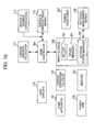
- the smart storage 200 includes the battery 107 which is freely attached or detached, the device manager 201, and the storage system manager 202.
- the storage system manager 202 is configured to communicate with the battery management server 108 over the network.
- the energy generation apparatus 101 is provided.
- a renewable energy generation system for example, photovoltaic power generation
- a home instrument/home appliance 102 and energy/environment sensors 103 are included.
- the electric power is supplied to the home through an electric power grid 104.
- a display device 110 which provides information to the user is included.
- Various kinds of information for example, alarms which are detected when the storage system manager 202 performs control of charging and discharging the battery 107 are displayed on the display device 110.
- the emission amount calculator 111 is provided in connection with the home controller 204.
- the current household total power consumption which is detected by the home controller 204 is displayed on the display device 110.
- components illustrated by blocks may be formed as software, or software and chip sets running on hardware.
- a personal computer, a home appliance, a game console, a set-top box, a dedicated energy controller, and the storage system manager 202 are exemplified.
- an energy and emission amount trade market 112 and an energy and emission amount authentication 113 are associated with the home controller 204.
- the storage system manager 202 is configured of components which have all or a part of the following functions:
- the battery 107 corresponds to the batteries 107a, 107b, 107c, and 107d in Fig. 8 , which are standardized and have the following functions.
- the battery has the battery ID, and is authenticated by a unified authentication method using the battery ID.
- the battery ID is information for identifying the battery uniquely, in which digital data having a plurality of bits is used.
- serial number may be used.
- digital data with a hierarchical structure may be used in which a plurality of attributes such as the manufacturer and type is used.
- the battery 107 is connected to the battery management server 108 via the network, and is managed by the battery management server 108 via the network.
- the battery 107 is regulated by a unified standard on the connection with the storage system manager 202, and the connection with other application devices (electric bicycle, etc.). As described above, the battery 107 is inserted into the socket which is included in the storage system manager 202. By inserting the battery 107 into the storage system manager 202, the smart storage 200 is configured.
- a battery which is used as the battery 107 at home or in mobile devices there are various kinds of energy devices such as a primary cell, a secondary cell, a capacitor, a photovoltaic solar cell, and a fuel cell. These energy devices can be connected to the storage system manager 202 through the interface with a common standardized device manager.
- the device manager is a detachable socket.
- an authentication protocol between the battery 107 and the storage system manager 202 and a control protocol such as for charge are standardized regarding all of the energy devices.
- the battery ID is an identifier for managing the battery, which is data fixed in length for specifying the battery uniquely.
- the "battery” is used as a terminology which represents both a battery cell (power generation section) and a battery pack in which the battery cell and a protection circuit are integrated in an outer case.
- the battery ID becomes essential for the management and the authentication of the battery 107.
- the "authentication” described above includes an authentication between the battery 107 and the charge device (which is included in the storage system manager 202), an authentication between the battery 107 and an application, and an authentication between the storage system manager 202 and the battery management server 108.
- the battery ID or a charge interface is set to be in a unified standardized, and the authentication module is mounted on the battery 107 or each apparatus to perform authentication. Through the authentication, it is checked whether the battery 107 or each apparatus is a regular product or not. Further, a control can be performed, for example, checking normal operations, in an integrated fashion, and a fire accident caused by non-standardized connection can be prevented.
- a method of mounting software on a microcomputer within the battery, a method of building an authentication chip in the battery, and the like are exemplified.
- a communication method for authentication a method of using a communication interface such as UART (Universal Asynchronous Receiver-Transceiver: asynchronous serial communication transmitting and receiving circuit) and a method of using a sensor network according to a wireless communication standard such as Bluetooth, ZigBee, and Wi-Fi are exemplified.
- the Bluetooth scheme is applied to a multimedia communication, and can perform point-to-multipoint communication.
- the ZigBee uses a physical layer of IEEE (Institute of Electrical and Electronics Engineers) 802.15.4.
- IEEE 802.15.4 is a name of a short-range wireless network standard which is called PAN (Personal Area Network) or WPAN (Wireless PAN).
- the battery management server 108 has the following functions.
- the output power and the capacity of the battery vary based on an application.
- the shapes and the I/O terminals (sockets) of the batteries are configured in a unified standard and connected to each other, so that battery modules optimized for each application can be configured.
- compatibility (output power, capacity, etc.) of the configured battery module with the application or charge current/voltage control can be verified by inquiring of the battery management server 108 via the storage system manager 202. Therefore, safe and appropriate use can be achieved by a plurality of the applications of the battery.
- Each battery 107 is written with the battery ID at the time of manufacturing.
- the battery ID is stored in a protective area of a microcomputer memory in the battery.
- the battery ID is stored in a nonvolatile memory in the authentication chip.
- the battery ID includes data (manufacturer, model number, manufacture date, manufacture place, line number, serial number, version information, etc.) for specifying the battery uniquely.
- the charge device storage system manager 202 is also assigned an ID (a unique device ID for the device).
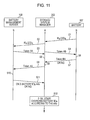
- the charge device After performing an authentication protocol shown in Fig. 11 , if the authentication is established, the charge device begins to charge the battery. In Fig. 11 , the authentication performed between the battery 107 and the storage system manager 202 and the authentication performed between the storage system manager 202 and the battery management server 108 are shown.
- the storage system manager 202 may begin to charge the battery 107. Therefore, even under circumstances where the network is not connected, the battery 107 can be charged.
- the letter “B” is used for representing the battery 107
- the letter “A” is used for representing the storage system manager (charge device) 202
- the letter “S” is used for representing the battery management server 108.
- the abbreviated reference numerals as described above will be used.
- Tokens in the authentication protocol shown in Fig. 11 are as follows:
- the authentication protocol is performed as follows:
- the battery management server S monitors the operations of the battery B and the storage system manager A, and issues an alarm to the storage system manager A when it is detected that data is deviated from that during normal operations.
- a charge completion message is displayed on the display device of the storage system manager A.
- the status of the corresponding battery B is updated in the battery management server S. Then, a session between the battery management server S and the storage system manager A is disconnected.
- the storage system manager A When the storage system manager A receives NG from the battery management server S, it is determined that the authentication fails, and a message representing that the authentication fails is displayed on the display device of the storage system manager A. In this case, the storage system manager A does not start the charge operation of the battery B.
- the order of the above-mentioned authentication protocol is an example, and the mutual authentication between the battery management server S and the storage system manager A can be separately performed in parallel with the mutual authentication between the storage system manager A and the battery B. Accordingly, an authentication time can be shortened.
- the mutual authentication is performed in advance between the battery management server S and the storage system manager A and the network is connected, the mutual authentication is performed only between the storage system manager A and the battery B. Then the fact that the authentication is completed is informed to the battery management server S and the abnormality/accident information, recall information, or the charge control information of the battery B is obtained in Step S11, so that the charge starts.
- the user can select a mode in which there is no inquiry to the battery management server.
- the processes for the mutual authentication between the storage system manager A and the battery B (Steps S1, S4, S6, S7, and S8) are completed, the charge starts.
- the charge control information is stored in a recording medium which is packaged within the battery.
- the abnormality/accident information, the recall information, or the charge control information of the battery B cannot be obtained from the battery management server S.
- the latest information of the battery being used is always maintained in a home network.
- the network disconnection (off-line) mode the information is used by an instruction of the user.
- the storage system manager A maintains the status of the battery, which is sent next time when the battery management server is connected. Based on the information, the battery management server updates the battery information.
- randomness in random numbers RS, RA, and RB which is generated in the respective entities is important.
- a random number generation module can be considered to be mounted, but mounting the random number generation module on each battery is not realistic in view of resources and cost. In the battery, it is taken into consideration that a lower bit data of a current value having a large difference is generated by combining time information, the battery ID or the like.
- the authentication process described above is a process in the case of charging the battery.
- the mutual authentication is performed between the battery and the application.
- the mutual authentication when the battery is being used is also performed by the same protocol as that of the mutual authentication between the above-mentioned storage system manager and the battery.
- the discharge starts after the authentication protocol shown in Fig. 12 is performed, so that the application 109 becomes available.
- the application 109 is also assigned an ID.
- the mutual authentications of the battery B, the battery management server S, and the system manager A are completed in advance by the protocol as shown in Fig. 11 , and the network is being connected.
- Tokens in the authentication protocol shown in Fig. 12 are as follows:
- the authentication protocol is performed as follows:
- the storage system manager 202 monitors the operations of the battery 107 and the application 109, and displays an alarm on the display device 110 when it is detected that data is deviated from that during normal operations.
- battery use information is periodically uploaded to the battery management server 108.
- the application 109 is a mobile application, it sends information to the battery management server 108 or the storage system manager 202 via an external network from the outside, and performs control of monitoring on the basis of the above-mentioned control.
Landscapes
- Engineering & Computer Science (AREA)
- Power Engineering (AREA)
- Microelectronics & Electronic Packaging (AREA)
- Manufacturing & Machinery (AREA)
- Chemical & Material Sciences (AREA)
- Chemical Kinetics & Catalysis (AREA)
- Electrochemistry (AREA)
- General Chemical & Material Sciences (AREA)
- Physics & Mathematics (AREA)
- General Physics & Mathematics (AREA)
- Automation & Control Theory (AREA)
- General Engineering & Computer Science (AREA)
- Electromagnetism (AREA)
- Radar, Positioning & Navigation (AREA)
- Charge And Discharge Circuits For Batteries Or The Like (AREA)
- Supply And Distribution Of Alternating Current (AREA)
Applications Claiming Priority (4)
| Application Number | Priority Date | Filing Date | Title |
|---|---|---|---|
| US16805409P | 2009-04-09 | 2009-04-09 | |
| US16876709P | 2009-04-13 | 2009-04-13 | |
| US12/731,929 US9318917B2 (en) | 2009-04-09 | 2010-03-25 | Electric storage apparatus and power control system |
| PCT/JP2010/056632 WO2010117082A1 (fr) | 2009-04-09 | 2010-04-07 | Dispositif d'alimentation électrique et système de commande d'alimentation électrique |
Publications (2)
| Publication Number | Publication Date |
|---|---|
| EP2418749A1 true EP2418749A1 (fr) | 2012-02-15 |
| EP2418749A4 EP2418749A4 (fr) | 2012-09-05 |
Family
ID=42935026
Family Applications (1)
| Application Number | Title | Priority Date | Filing Date |
|---|---|---|---|
| EP10761780A Withdrawn EP2418749A4 (fr) | 2009-04-09 | 2010-04-07 | Dispositif d'alimentation électrique et système de commande d'alimentation électrique |
Country Status (6)
| Country | Link |
|---|---|
| US (2) | US9318917B2 (fr) |
| EP (1) | EP2418749A4 (fr) |
| JP (1) | JP6009161B2 (fr) |
| KR (1) | KR20120005450A (fr) |
| CN (1) | CN102379075B (fr) |
| WO (1) | WO2010117082A1 (fr) |
Cited By (2)
| Publication number | Priority date | Publication date | Assignee | Title |
|---|---|---|---|---|
| US11567551B2 (en) | 2020-07-28 | 2023-01-31 | Rohde & Schwarz Gmbh & Co. Kg | Adaptive power supply |
| EP4262045A1 (fr) | 2022-04-13 | 2023-10-18 | Andreas Stihl AG & Co. KG | Système de gestion de la charge de batterie et?procédé de gestion de la charge de batterie |
Families Citing this family (90)
| Publication number | Priority date | Publication date | Assignee | Title |
|---|---|---|---|---|
| JP5685715B2 (ja) * | 2009-09-28 | 2015-03-18 | パナソニックIpマネジメント株式会社 | 系統連系形給電システム |
| US20110202194A1 (en) * | 2010-02-15 | 2011-08-18 | General Electric Company | Sub-metering hardware for measuring energy data of an energy consuming device |
| JP5126308B2 (ja) * | 2010-07-09 | 2013-01-23 | ソニー株式会社 | 電力コントロール装置 |
| KR101729019B1 (ko) | 2010-10-12 | 2017-04-21 | 삼성전자주식회사 | 전력 관리 장치, 그를 가지는 전력 관리 시스템 및 그 제어 방법 |
| CN102437584A (zh) * | 2010-10-27 | 2012-05-02 | 上海市电力公司 | 智能电网中应用电动汽车作为移动储能设备的系统和方法 |
| KR101210645B1 (ko) * | 2010-12-01 | 2012-12-07 | 엠씨테크놀로지 (주) | Led 조명시스템 |
| KR20120072224A (ko) * | 2010-12-23 | 2012-07-03 | 한국전자통신연구원 | 전력 획득 예측에 기반한 센서 노드의 전원 제어 장치 및 방법 |
| JP5646352B2 (ja) * | 2011-01-19 | 2014-12-24 | シャープ株式会社 | 放電制御装置、放電制御方法、放電制御システム、制御プログラムおよび記録媒体 |
| JP2012186950A (ja) * | 2011-03-07 | 2012-09-27 | Denso Corp | 電力供給システム |
| JP5323113B2 (ja) * | 2011-03-16 | 2013-10-23 | 株式会社東芝 | 電力利用調整装置、システムおよびプログラム |
| JP5259763B2 (ja) * | 2011-03-25 | 2013-08-07 | 株式会社東芝 | 電力管理装置、システム及び方法 |
| JP2012252580A (ja) * | 2011-06-03 | 2012-12-20 | Sony Corp | 電力制御装置、電力管理装置および電力管理システム |
| US20120320281A1 (en) * | 2011-06-14 | 2012-12-20 | Teruo Kinoshita | Television receiver apparatus and control method |
| JP5909906B2 (ja) * | 2011-07-21 | 2016-04-27 | ソニー株式会社 | 情報処理装置、情報処理方法、プログラム、記録媒体、及び情報処理システム |
| ES2748199T3 (es) | 2011-07-26 | 2020-03-13 | Gogoro Inc | Aparato, método y artículo para proporcionar información sobre la disponibilidad de dispositivos de almacenamiento de energía en una máquina de recogida, carga y distribución de dispositivos de almacenamiento de energía |
| ES2692524T3 (es) | 2011-07-26 | 2018-12-04 | Gogoro Inc. | Aparato, método y artículo para proporcionar datos de diagnóstico de vehículo |
| WO2013016564A2 (fr) | 2011-07-26 | 2013-01-31 | Gogoro, Inc. | Appareil, procédé et article permettant de reserver des dispositifs de stockage de puissance au niveau de machines de collecte, de charge et de distribution de dispositifs de stockage de puissance |
| US9552682B2 (en) * | 2011-07-26 | 2017-01-24 | Gogoro Inc. | Apparatus, method and article for redistributing power storage devices, such as batteries, between collection, charging and distribution machines |
| US10186094B2 (en) | 2011-07-26 | 2019-01-22 | Gogoro Inc. | Apparatus, method and article for providing locations of power storage device collection, charging and distribution machines |
| US9124098B2 (en) * | 2011-08-08 | 2015-09-01 | General Electric Company | Managing excess renewable energy |
| US8924034B2 (en) * | 2011-09-01 | 2014-12-30 | Sharp Laboratories Of America, Inc. | Energy management system |
| JP5731941B2 (ja) * | 2011-09-30 | 2015-06-10 | 株式会社東芝 | 充放電指示装置、充放電指示方法、及び充放電指示プログラム |
| JP5701730B2 (ja) * | 2011-09-30 | 2015-04-15 | 株式会社東芝 | 充放電判定装置、充放電判定方法、及び充放電判定プログラム |
| US9515489B2 (en) * | 2011-11-07 | 2016-12-06 | Global Link Co., Ltd. | Feed system to be used in residence such as multi-unit apartment complex |
| US9651927B2 (en) * | 2011-11-24 | 2017-05-16 | Kyocera Corporation | Power supply control system and power supply control method |
| US9600434B1 (en) | 2011-12-30 | 2017-03-21 | Bedrock Automation Platforms, Inc. | Switch fabric having a serial communications interface and a parallel communications interface |
| US8868813B2 (en) | 2011-12-30 | 2014-10-21 | Bedrock Automation Platforms Inc. | Communications control system with a serial communications interface and a parallel communications interface |
| US9437967B2 (en) | 2011-12-30 | 2016-09-06 | Bedrock Automation Platforms, Inc. | Electromagnetic connector for an industrial control system |
| US9467297B2 (en) | 2013-08-06 | 2016-10-11 | Bedrock Automation Platforms Inc. | Industrial control system redundant communications/control modules authentication |
| US11144630B2 (en) | 2011-12-30 | 2021-10-12 | Bedrock Automation Platforms Inc. | Image capture devices for a secure industrial control system |
| US8971072B2 (en) | 2011-12-30 | 2015-03-03 | Bedrock Automation Platforms Inc. | Electromagnetic connector for an industrial control system |
| US10834820B2 (en) | 2013-08-06 | 2020-11-10 | Bedrock Automation Platforms Inc. | Industrial control system cable |
| US11967839B2 (en) | 2011-12-30 | 2024-04-23 | Analog Devices, Inc. | Electromagnetic connector for an industrial control system |
| US9727511B2 (en) | 2011-12-30 | 2017-08-08 | Bedrock Automation Platforms Inc. | Input/output module with multi-channel switching capability |
| US10834094B2 (en) | 2013-08-06 | 2020-11-10 | Bedrock Automation Platforms Inc. | Operator action authentication in an industrial control system |
| US11314854B2 (en) | 2011-12-30 | 2022-04-26 | Bedrock Automation Platforms Inc. | Image capture devices for a secure industrial control system |
| US8862802B2 (en) | 2011-12-30 | 2014-10-14 | Bedrock Automation Platforms Inc. | Switch fabric having a serial communications interface and a parallel communications interface |
| US12061685B2 (en) | 2011-12-30 | 2024-08-13 | Analog Devices, Inc. | Image capture devices for a secure industrial control system |
| US9191203B2 (en) | 2013-08-06 | 2015-11-17 | Bedrock Automation Platforms Inc. | Secure industrial control system |
| CA2864758A1 (fr) * | 2012-01-20 | 2013-08-25 | Energy Aware Technology Inc. | Systeme et procede de compilation et d'organisation de donnees de consommation d'energie et de conversion de ces donnees en un ou plusieurs formats pouvant donner lieu a une actio n d'utilisateur |
| WO2013121514A1 (fr) * | 2012-02-14 | 2013-08-22 | 東芝三菱電機産業システム株式会社 | Dispositif d'égalisation de puissance |
| JP2013218909A (ja) * | 2012-04-10 | 2013-10-24 | Toshiba Corp | 電池情報管理サーバ、電池情報記録装置、及び電池情報管理システム |
| CN104247194A (zh) * | 2012-04-26 | 2014-12-24 | 索尼公司 | 电力控制装置和电力消费装置 |
| DE102012207668A1 (de) | 2012-05-09 | 2013-11-14 | Robert Bosch Gmbh | Computerimplementiertes Verfahren zum Generieren von Software, Batterie und Kraftfahrzeug |
| US20190317463A1 (en) | 2012-05-19 | 2019-10-17 | Growing Energy Labs, Inc. | Adaptive energy storage operating system for multiple economic services |
| US9817376B1 (en) | 2012-05-19 | 2017-11-14 | Growing Energy Labs, Inc. | Adaptive energy storage operating system for multiple economic services |
| CN104995652A (zh) | 2012-07-12 | 2015-10-21 | 新星闪耀有限公司 | 一种按需型电力系统和方法 |
| US9985468B2 (en) * | 2012-07-12 | 2018-05-29 | Nova Lumos Ltd. | Secured on-demand energy systems |
| KR101631064B1 (ko) | 2012-08-06 | 2016-06-16 | 삼성에스디아이 주식회사 | 배터리 팩의 전압 측정 방법 및 이를 포함하는 에너지 저장 시스템 |
| WO2014024200A1 (fr) * | 2012-08-08 | 2014-02-13 | Ghost Rohit Neil | Dispositif pour générer de l'électricité par exploitation d'énergie solaire et procédé y correspondant |
| JP5800995B2 (ja) * | 2012-09-20 | 2015-10-28 | 三菱電機株式会社 | 家電機器 |
| US9727720B2 (en) * | 2012-11-30 | 2017-08-08 | Certicom Corp. | Challenge-response authentication using a masked response value |
| US11222485B2 (en) | 2013-03-12 | 2022-01-11 | Gogoro Inc. | Apparatus, method and article for providing information regarding a vehicle via a mobile device |
| ES2802906T3 (es) | 2013-03-15 | 2021-01-21 | Gogoro Inc | Sistema modular para la recogida y distribución de dispositivos de almacenamiento eléctrico |
| EP2782375A1 (fr) * | 2013-03-20 | 2014-09-24 | Eff'Innov Technologies | Dispositif intelligent d'alimentation en énergie et procédé correspondant pour utiliser un dispositif d'alimentation |
| CN104281802A (zh) * | 2013-07-01 | 2015-01-14 | 宏达国际电子股份有限公司 | 无线充电验证的方法及相关无线充电系统 |
| DE102014003054B4 (de) | 2013-07-09 | 2022-03-17 | Sew-Eurodrive Gmbh & Co Kg | Verfahren zur Leistungsregelung eines Systems und Vorrichtung zur Leistungsregelung eines Systems |
| US20150048684A1 (en) * | 2013-08-06 | 2015-02-19 | Bedrock Automation Platforms Inc. | Secure power supply for an industrial control system |
| US10613567B2 (en) | 2013-08-06 | 2020-04-07 | Bedrock Automation Platforms Inc. | Secure power supply for an industrial control system |
| KR102125331B1 (ko) | 2013-11-07 | 2020-06-22 | 삼성전자 주식회사 | 스마트 플러그에 연결된 전자장치를 검출하기 위한 방법 및 장치 |
| US9329611B2 (en) * | 2013-12-02 | 2016-05-03 | Nxp B.V. | Power control |
| CN105099692B (zh) * | 2014-05-22 | 2020-01-14 | 创新先进技术有限公司 | 安全校验方法、装置、服务器及终端 |
| CN105281061A (zh) | 2014-07-07 | 2016-01-27 | 基岩自动化平台公司 | 工业控制系统电缆 |
| KR20170098790A (ko) * | 2014-07-31 | 2017-08-30 | 그로잉 에너지 랩스, 인크. | 적응형 자동화 제어 소프트웨어에 의한 에너지 저장 수명 성능 예측 및 최적화 |
| TWI603552B (zh) | 2014-08-11 | 2017-10-21 | 睿能創意公司 | 多方向性的電連接器、插頭及系統 |
| ES2914287T3 (es) | 2014-09-04 | 2022-06-08 | Gogoro Inc | Módulo de carga para un sistema de distribución bidireccional de dispositivos de almacenamiento de energía eléctrica |
| FR3028684A1 (fr) * | 2014-11-14 | 2016-05-20 | Orange | Technique de gestion de la consommation electrique dans un reseau de communication local |
| WO2016109562A1 (fr) * | 2014-12-29 | 2016-07-07 | Fillit Marielle Damara | Système solaire domestique destiné à tous les services ménagers |
| EP3840168A1 (fr) * | 2015-04-13 | 2021-06-23 | Bedrock Automation Platforms Inc. | Alimentation sécurisée pour un système de commande industriel |
| WO2016199816A1 (fr) * | 2015-06-08 | 2016-12-15 | 京セラ株式会社 | Dispositif de conversion de puissance, dispositif de gestion de puissance et procédé de gestion de puissance |
| EP3306771B1 (fr) * | 2015-06-08 | 2019-11-27 | Kyocera Corporation | Dispositif de conversion d'énergie électrique, dispositif de gestion d'énergie électrique et procédé de gestion d'énergie électrique |
| DE102015109113B4 (de) * | 2015-06-09 | 2018-10-31 | Volllast Gmbh | Speichereinheit für einen Verbraucher, Speichersystem sowie Verfahren zur Steuerung eines Speichersystems |
| US20180175333A1 (en) * | 2015-06-16 | 2018-06-21 | Sony Corporation | Battery, battery can, battery pack, electronic device, electric vehicle, power storage device, and power system |
| US10250034B2 (en) * | 2015-08-26 | 2019-04-02 | Abb Schweiz Ag | Distributed utility resource planning and forecast |
| US10209750B2 (en) * | 2016-05-02 | 2019-02-19 | Samsung Electronics Co., Ltd. | SSD driven system level thermal management |
| WO2018012338A1 (fr) * | 2016-07-15 | 2018-01-18 | 日本電気株式会社 | Dispositif de détermination, dispositif de surveillance, système de stockage d'énergie, système de surveillance, procédé de détermination, procédé de surveillance, procédé de fonctionnement d'un système de stockage d'énergie et programme |
| CN106297043B (zh) * | 2016-08-22 | 2019-03-05 | 深圳易马达科技有限公司 | 基于物联网的电池租用系统及方法 |
| US10650621B1 (en) | 2016-09-13 | 2020-05-12 | Iocurrents, Inc. | Interfacing with a vehicular controller area network |
| JP6688726B2 (ja) * | 2016-12-26 | 2020-04-28 | 株式会社シマノ | 自転車用制御装置および自転車用制御システム |
| US11121555B2 (en) | 2017-03-20 | 2021-09-14 | Jabil Inc. | Apparatus, system and method of providing power in an office environment |
| KR20190015655A (ko) * | 2017-08-03 | 2019-02-14 | (주)비에이에너지 | 건물벽체 내장용 에너지 자립형 무선 통신 파워 컨트롤 장치 |
| CN109450005A (zh) * | 2018-10-30 | 2019-03-08 | 北京小米移动软件有限公司 | 插排的控制方法及装置 |
| EP3667856B1 (fr) * | 2018-12-12 | 2021-11-03 | CraftStrom Limited | Système d'allocation d'énergie |
| WO2020203377A1 (fr) * | 2019-04-01 | 2020-10-08 | パナソニックIpマネジメント株式会社 | Système de gestion de batteries et procédé de gestion de batteries |
| US11561592B2 (en) * | 2020-05-08 | 2023-01-24 | Canon Kabushiki Kaisha | Power receiving apparatus and control method |
| AU2020453850A1 (en) * | 2020-06-17 | 2023-02-02 | Kabushiki Kaisha Toshiba | Energy management system, energy management method, and storage medium |
| JP2022028583A (ja) * | 2020-08-03 | 2022-02-16 | 直男 久保田 | 電気で動くモーターを使った四輪車、二輪車(自転車を除く)、飛行機、ドローンをカートリッヂ式のバッテリーにする |
| CN115411764B (zh) * | 2021-05-27 | 2025-03-25 | 华为数字能源技术有限公司 | 一种储能系统、物理位置识别方法及光伏发电系统 |
| WO2023067579A1 (fr) * | 2021-10-23 | 2023-04-27 | Modi Sanskar | Système intelligent de gestion de batterie d'un véhicule électrique |
| WO2026003612A1 (fr) | 2024-06-27 | 2026-01-02 | Maserati S.P.A. | Procédé de détermination du courant de charge cible d'une batterie haute tension d'un véhicule électrique à partir d'un état de charge cible et d'un temps de charge cible fixé par un utilisateur |
Family Cites Families (29)
| Publication number | Priority date | Publication date | Assignee | Title |
|---|---|---|---|---|
| DE1178941B (de) * | 1963-04-19 | 1964-10-01 | Deutsche Bundespost | Schaltungsanordnung zur Inbetriebnahme und zum Betrieb einer mit Gleichstrom betriebenen Gasentladungslampe mit konstant gehaltenem Brennstrom |
| US5619117A (en) * | 1982-06-07 | 1997-04-08 | Norand Corporation | Battery pack having memory |
| US6218806B1 (en) * | 1998-06-03 | 2001-04-17 | Black & Decker Inc. | Method and apparatus for obtaining product use information |
| JP3519969B2 (ja) * | 1999-02-02 | 2004-04-19 | 三洋電機株式会社 | 電話装置 |
| JP3239106B2 (ja) | 1999-02-03 | 2001-12-17 | ミサワホーム株式会社 | 建 物 |
| US7227335B2 (en) * | 2003-07-22 | 2007-06-05 | Makita Corporation | Method and apparatus for diagnosing the condition of a rechargeable battery |
| KR100631578B1 (ko) | 2004-07-30 | 2006-10-09 | 엘지전자 주식회사 | 휴대단말기 배터리부 식별장치 및 방법 |
| EP1805863B1 (fr) * | 2004-10-18 | 2013-06-26 | Black & Decker, Inc. | Systeme electrique sans fil |
| JP2006158146A (ja) | 2004-12-01 | 2006-06-15 | Toko Electric Corp | 電力用供給管理システム |
| JP3833679B2 (ja) * | 2004-12-02 | 2006-10-18 | ソニー株式会社 | 電池パックおよび充電制御方法 |
| JP4945077B2 (ja) * | 2004-12-03 | 2012-06-06 | シャープ株式会社 | 蓄電設備管理システム |
| CN100583759C (zh) * | 2004-12-13 | 2010-01-20 | 华为技术有限公司 | 实现不同认证控制设备间同步认证的方法 |
| JP3838258B2 (ja) * | 2005-03-10 | 2006-10-25 | ソニー株式会社 | バッテリー残量表示方法 |
| DE102006028930A1 (de) | 2006-06-23 | 2007-12-27 | Arno Richard Doerr | System zur Erzeugung von Energie in Kraft/Wärme-Kopplung |
| JP4386057B2 (ja) * | 2006-08-10 | 2009-12-16 | ソニー株式会社 | バッテリー装置 |
| JP4949902B2 (ja) * | 2007-03-16 | 2012-06-13 | 日本碍子株式会社 | 二次電池の電力制御方法 |
| JP4842885B2 (ja) | 2007-05-23 | 2011-12-21 | トヨタ自動車株式会社 | 車載機器制御システムおよび車両 |
| KR20100061453A (ko) * | 2007-07-25 | 2010-06-07 | 트루라이트 인크. | 하이브리드 전력의 생성 및 사용을 관리하는 장치, 시스템 및 방법 |
| US20100017045A1 (en) * | 2007-11-30 | 2010-01-21 | Johnson Controls Technology Company | Electrical demand response using energy storage in vehicles and buildings |
| US7956570B2 (en) * | 2008-01-07 | 2011-06-07 | Coulomb Technologies, Inc. | Network-controlled charging system for electric vehicles |
| US8531162B2 (en) * | 2008-06-16 | 2013-09-10 | International Business Machines Corporation | Network based energy preference service for managing electric vehicle charging preferences |
| EP2321885A2 (fr) * | 2008-08-14 | 2011-05-18 | Simplure, Llc. | Systèmes et procédés pour conditionner et contrôler une consommation d'électricité |
| US8085034B2 (en) * | 2008-10-31 | 2011-12-27 | Yaniv Sirton | Managing charging of electric vehicles |
| WO2011099291A1 (fr) * | 2010-02-12 | 2011-08-18 | パナソニック株式会社 | Appareil de transaction d'énergie électrique et procédé de commande d'appareil de transaction d'énergie électrique |
| JP5630176B2 (ja) * | 2010-09-16 | 2014-11-26 | ソニー株式会社 | 電力供給装置 |
| JP5221638B2 (ja) * | 2010-12-28 | 2013-06-26 | 株式会社東芝 | 制御装置、制御方法及び制御プログラム |
| US8463449B2 (en) * | 2011-01-28 | 2013-06-11 | Dean Sanders | Systems, apparatus, and methods of a solar energy grid integrated system with energy storage appliance |
| JP2012252580A (ja) * | 2011-06-03 | 2012-12-20 | Sony Corp | 電力制御装置、電力管理装置および電力管理システム |
| JP6064337B2 (ja) * | 2011-08-10 | 2017-01-25 | ソニー株式会社 | 給電システム、給電装置および電子機器 |
-
2010
- 2010-03-25 US US12/731,929 patent/US9318917B2/en not_active Expired - Fee Related
- 2010-04-07 KR KR1020117023244A patent/KR20120005450A/ko not_active Withdrawn
- 2010-04-07 CN CN201080014427.7A patent/CN102379075B/zh not_active Expired - Fee Related
- 2010-04-07 EP EP10761780A patent/EP2418749A4/fr not_active Withdrawn
- 2010-04-07 WO PCT/JP2010/056632 patent/WO2010117082A1/fr not_active Ceased
- 2010-04-07 JP JP2011508408A patent/JP6009161B2/ja not_active Expired - Fee Related
-
2015
- 2015-10-22 US US14/920,415 patent/US20160043554A1/en not_active Abandoned
Cited By (2)
| Publication number | Priority date | Publication date | Assignee | Title |
|---|---|---|---|---|
| US11567551B2 (en) | 2020-07-28 | 2023-01-31 | Rohde & Schwarz Gmbh & Co. Kg | Adaptive power supply |
| EP4262045A1 (fr) | 2022-04-13 | 2023-10-18 | Andreas Stihl AG & Co. KG | Système de gestion de la charge de batterie et?procédé de gestion de la charge de batterie |
Also Published As
| Publication number | Publication date |
|---|---|
| US20160043554A1 (en) | 2016-02-11 |
| US20100262312A1 (en) | 2010-10-14 |
| KR20120005450A (ko) | 2012-01-16 |
| CN102379075B (zh) | 2015-08-19 |
| JPWO2010117082A1 (ja) | 2012-10-18 |
| JP6009161B2 (ja) | 2016-10-19 |
| US9318917B2 (en) | 2016-04-19 |
| CN102379075A (zh) | 2012-03-14 |
| WO2010117082A1 (fr) | 2010-10-14 |
| EP2418749A4 (fr) | 2012-09-05 |
Similar Documents
| Publication | Publication Date | Title |
|---|---|---|
| EP2418749A1 (fr) | Dispositif d'alimentation électrique et système de commande d'alimentation électrique | |
| JP6823818B2 (ja) | 電池搭載機器の保守運用方法 | |
| US9263916B2 (en) | Power management system, power management apparatus, and power management method | |
| US8683236B2 (en) | Outlet expansion appartus containing a delegate authentication unit to perform authentication of an electronic appliance with a power management apparatus | |
| JP5890513B2 (ja) | 制御装置、制御システム及び蓄電池制御方法 | |
| CN102264006B (zh) | 储电管理系统及其操作方法、信息处理装置及储电装置 | |
| CN102656770B (zh) | 电力控制方法、通信装置及电力控制系统 | |
| CN104685834B (zh) | 管理系统、管理方法和设备 | |
| KR20190040414A (ko) | 무선 배터리 관리 장치 및 이를 포함하는 배터리팩 | |
| KR20130006949A (ko) | 전기자동차 충전 방법 | |
| US20110184584A1 (en) | Power management apparatus, power management system, and method of controlling appliance | |
| CN102971950A (zh) | 电力控制装置 | |
| CN119497680A (zh) | 在不动产的充电点处为电动车辆充电 | |
| CN113259892A (zh) | 一种无线数据采集系统 | |
| JP2003174726A (ja) | 電源装置の運転管理システム | |
| KR102382196B1 (ko) | 육상전력공급장치(amp)로부터 전력을 공급받아 에너지를 이용하는 중소형 선박용 에너지관리시스템 | |
| JP6678393B2 (ja) | 蓄電システム及びその制御方法 | |
| CN218449550U (zh) | 用于电池管理的系统、电源 | |
| JP2008227612A (ja) | 通信システム、同通信システムを構成する各端末装置間の接続経路設定方法、及び同通信システムに用いる端末装置 | |
| TWI859802B (zh) | 電池交換之資訊管理方法及系統 | |
| US9182247B2 (en) | Network system | |
| TWI285476B (en) | Renewable energy-powered wireless communication device and the management system utilizing the same | |
| CN120454316A (zh) | 一种基于无线通信的家庭储能系统及方法 | |
| CN206685909U (zh) | 一种基于电池堆的智能储能系统 | |
| EP2568657A1 (fr) | Système de réseau |
Legal Events
| Date | Code | Title | Description |
|---|---|---|---|
| PUAI | Public reference made under article 153(3) epc to a published international application that has entered the european phase |
Free format text: ORIGINAL CODE: 0009012 |
|
| 17P | Request for examination filed |
Effective date: 20111004 |
|
| AK | Designated contracting states |
Kind code of ref document: A1 Designated state(s): AT BE BG CH CY CZ DE DK EE ES FI FR GB GR HR HU IE IS IT LI LT LU LV MC MK MT NL NO PL PT RO SE SI SK SM TR |
|
| DAX | Request for extension of the european patent (deleted) | ||
| A4 | Supplementary search report drawn up and despatched |
Effective date: 20120802 |
|
| RIC1 | Information provided on ipc code assigned before grant |
Ipc: B25F 5/00 20060101ALI20120727BHEP Ipc: H02J 7/00 20060101ALI20120727BHEP Ipc: H01M 10/48 20060101ALI20120727BHEP Ipc: G01R 31/36 20060101ALI20120727BHEP Ipc: H02J 7/34 20060101ALI20120727BHEP Ipc: H02J 3/32 20060101AFI20120727BHEP Ipc: G05F 1/66 20060101ALI20120727BHEP Ipc: H01M 10/42 20060101ALI20120727BHEP |
|
| 17Q | First examination report despatched |
Effective date: 20130320 |
|
| STAA | Information on the status of an ep patent application or granted ep patent |
Free format text: STATUS: EXAMINATION IS IN PROGRESS |
|
| GRAP | Despatch of communication of intention to grant a patent |
Free format text: ORIGINAL CODE: EPIDOSNIGR1 |
|
| STAA | Information on the status of an ep patent application or granted ep patent |
Free format text: STATUS: GRANT OF PATENT IS INTENDED |
|
| INTG | Intention to grant announced |
Effective date: 20180711 |
|
| STAA | Information on the status of an ep patent application or granted ep patent |
Free format text: STATUS: THE APPLICATION IS DEEMED TO BE WITHDRAWN |
|
| 18D | Application deemed to be withdrawn |
Effective date: 20181122 |