EP2418977B1 - Dispositif de mesure de vêtement - Google Patents
Dispositif de mesure de vêtement Download PDFInfo
- Publication number
- EP2418977B1 EP2418977B1 EP09787706.2A EP09787706A EP2418977B1 EP 2418977 B1 EP2418977 B1 EP 2418977B1 EP 09787706 A EP09787706 A EP 09787706A EP 2418977 B1 EP2418977 B1 EP 2418977B1
- Authority
- EP
- European Patent Office
- Prior art keywords
- arm
- correspondence
- way
- supporting element
- length
- Prior art date
- Legal status (The legal status is an assumption and is not a legal conclusion. Google has not performed a legal analysis and makes no representation as to the accuracy of the status listed.)
- Not-in-force
Links
- 238000005259 measurement Methods 0.000 claims description 41
- 238000000605 extraction Methods 0.000 claims description 10
- 210000001624 hip Anatomy 0.000 description 11
- 125000006850 spacer group Chemical group 0.000 description 10
- 239000002184 metal Substances 0.000 description 7
- 230000000903 blocking effect Effects 0.000 description 6
- 230000008878 coupling Effects 0.000 description 4
- 238000010168 coupling process Methods 0.000 description 4
- 238000005859 coupling reaction Methods 0.000 description 4
- 239000004744 fabric Substances 0.000 description 2
- 210000004197 pelvis Anatomy 0.000 description 2
- 230000006978 adaptation Effects 0.000 description 1
- 230000009189 diving Effects 0.000 description 1
- 238000003780 insertion Methods 0.000 description 1
- 230000037431 insertion Effects 0.000 description 1
- 238000012423 maintenance Methods 0.000 description 1
- 238000000034 method Methods 0.000 description 1
- 238000011160 research Methods 0.000 description 1
- 230000000284 resting effect Effects 0.000 description 1
- 238000004904 shortening Methods 0.000 description 1
- 230000002459 sustained effect Effects 0.000 description 1
Images





Classifications
-
- A—HUMAN NECESSITIES
- A41—WEARING APPAREL
- A41H—APPLIANCES OR METHODS FOR MAKING CLOTHES, e.g. FOR DRESS-MAKING OR FOR TAILORING, NOT OTHERWISE PROVIDED FOR
- A41H1/00—Measuring aids or methods
- A41H1/02—Devices for taking measurements on the human body
- A41H1/04—Stands for taking measurements
Definitions
- the present invention refers to the tailor's technical field. In particular it refers to a device for the acquisition of measures for the realization or adjustment of clothing in general.
- the manual operation for measuring the waist is commonly made by turning around the waist of the person with the metre and reading the corresponding measure.
- the operation is not easy and often the operator cannot surround with the metre the body of the person in a precise way, especially if he's of small bulk. It is then frequent the case where the metre does not perfectly surround the waist of the client but result to be raised or dropped from it, maybe because it is not sufficiently tight. If the operator does not have much experience it is then frequent the case where the measure is not correct, causing a not good final result and a clothing that have not much precise measures.
- the measurement in the inner part of the leg for example for the realization or adjustment of a trousers, can create discomfort to both the operator and the client.
- the proposed solution comprises a bar 3 projecting a graduated scale and supported by a supporting base 1.
- Different measuring arms (7, 8, 9) are assembled in a sliding manner on the bar thanks to the help of couplings 4. In such manner, by making the arms sliding along the bar until the desired height is reached, the relative height can be read and found.
- a measurement strip 22 can be assembled on one of such sleeves in such a way to bring it to the desired height and read the circumference measure.
- the patent GB 365,836 in the name of Caraceni describes a simple device for measuring a body, comprising a height adjustable stand with a graduated scale, a projecting reference arm and an attached tape measure.
- the prefixed aims are obtained through the realization of a telescopic arm 2, or rather in a way to result selectively stretchable or retractible in order to take a measurement on the body.
- the arm can lengthen and get retracted into therefore a chosen length to allow to read a measurement. In such way it results to be not much cumbersome when put back into the closing position at the end of the measurement and thus also easily transportable.
- the arm comprises fixing means (6) to fix it at a chosen extraction length in such a way to allow to operate, in correspondence of such length, a reading of the measurement of the body.
- the arm (2) comprises a portion with a fixed base (4) and at least an upper portion (5) selectively extractable or retractable from/to the inside of said fixed portion.
- the arm comprises a sole upper portion (5) selectively extractable or retractable from the portion with fixed base (4).
- the portion with fixed base (4) comprises always a supporting base (3) in such a way that the arm (2) can, in its complex, be placed on the ground in a way to be emerging upward.
- the mentioned means (11, 13, 15, 18) to take the measures of the clothes comprise at least a supporting element (15) comprising at least a device (13, 14, 18, 19) that allows to read at least a length and/or a width of the body.
- the supporting element (15) is placed in correspondence or closed to the upper end of the upper portion (5).
- a possible constructive solution can comprise a sole supporting element 15 placed in correspondence of the portion 5 placed above.
- the supporting element is place at the top of such portion.
- the above mentioned devices comprise at least a reference lever (13) or a bracket suitable to indicate the reaching of the chosen measuring point of the length of the cloth in correspondence of the lengthening or of the retracting of the arm.
- the reference lever can be, for example, integrated to the supporting element (15).
- the head can comprise a hook (14) to receive the reference lever.
- the hook (14) can then be of magnetic type while the lever (13) of metallic type in such a way to remain into the position on the hook.
- the supporting element is placed on the top of the portion 5 and comprises in an integrated or detached manner the bracket 13, it is also comprised a graduated scale (11) placed along said portion (5) and made in such a way to indicate the reached length in correspondence of the extraction or retraction of the upper portion (5) respect to the fixed base portion (4).
- the graduated scale works thus in combination with the reference bar 13 in a way to indicate the length measure of the body.
- the bar indicates the length where the extraction of the arm 2 must be stopped while the graduated scale indicates such length.
- a particularly advantageous solution comprises the graduated scale (11) engraved directly on the upper portion (5).
- the supporting element (15) comprises also a site (17) suitable to comprise a metre (18) configured to allow to take a measure of a circumference in correspondence of the chosen length of the arm.
- the site 17 for the metre can be placed at a height corresponding to 6. 5 centimetres from the bracket 13 when placed on the supporting element 15. In such manner, during the specific measurement of the crotch of a trouser, it is automatically obtained also the pelvis measurement independently from who takes these measures, even if the person has no experience.
- the site is closed at the top by an upper lid (16) in such a way to bind the metre within the site.
- the means (6) to fix the arm at the chosen length comprise a knob (7) and a carved spacer (8) and are configures with such a diameter to surround the upper portion (5).
- knob is made to get screwed at the upper end of the fixed portion (4) in such a way to close the spacer around the upper portion fixing it into the position or to get unscrewed to allow to the spacer to release the upper portion.
- This mechanism particularly simple constructively, allows to fix into the position the eventual movable portion/s 5 respect to the fixed one 4.
- Figure 1 shows, according to the invention, a complex view of the device for taking the measures on a body in general, particularly bodies of a person, for making clothing.
- the invention comprises an arm or bar 2 and means (11, 13, 15, 18) to allow to a user to take the measures that are specified further on in more detail.
- the arm 2 is sustained through a supporting base 3 in such a way to be placed on the ground and emerge upwards.
- the arm 2 is of telescopic type, or rather comprises some singular portions (indicated in the figure with the number 4 and 5) configured one inside the other in such a way to result selectively extractable and retractable.
- the arm result selectively stretchable and retractable and, according to such solution, the encumbrances in the retracted position are reduced as much as possible.
- the fixed base portion 4 comprising the above mentioned supporting base 3 is configured to receive at least an upper portion 5 sliding in its inside.
- the portion 4 is obviously hollowed, in such a way to be able to assemble in a sliding manner in its inside the different upper portions 5 (for such aim look also at the details of figure 2 and 3 ).
- the figure 1 described the preferred solution of the invention constituted by a sole portion 5 sliding within said base 4.
- a blocking element 6 that can be selectively screwed and unscrewed (look at figure 1 and figure 2 ), is fixed in correspondence of the upper free end of the portion 4 by means of a common thread 9. By screwing the element 6 it is possible to fix into the position the portion 5 in correspondence of the chosen position. At the same manner, by unscrewing the blocking element, it is possible to make the portion 5 sliding respect to the fixed portion 4, be able this way to lift it or re-enter it respect to the mentioned portion 4 exactly as indicated by the double arrow of figure 1 .
- the fixed portion 4 comprises the thread 9 in correspondence of its upper end in a way to be able to couple the blocking element 6 to it.
- the blocking element comprises in combination a knob or metal ring 7 and a carved spacer 10 in such a way to lean around the circular perimeter of the portion 4 without falling into it.
- figure 4 indicates the coupling between the spacer and the upper portion 5 destined to enter in the site of the base portion 4.
- the knob and the spacer have thus a passing coaxial hole to allow the passage of the portion 5 which results sliding respect to the fixed portion as described in figure 1 .
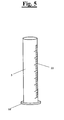
- the preferred solution of the invention comprises also a graduated scale 11 of length measurement directly obtained on the upper portion 5. Its functionality will be better explained later on.
- the upper end or the top of the portion 5 assembles a supporting element 15 for at least a device (13, 18) that allows the reading of the measures respect to the body, in particular the reading of a length and/or circumference.
- the supporting element can indifferently be in a sole piece with the mentioned portion 5 or separately connected to it.
- a reference bar 13 or bracket can be directly connected, for example welded, in a point of the perimeter of the supporting element 15.
- the supporting element comprises, according to the preferred solution, a shaped hook 14 to bind, by snap or through for example a magnet, the reference bar 13 (for such aim look at figure 1 and 6 ) of which the functionality will be better explained further on.
- the bar is then realized in two portions that result to be respectively pivoted. In such manner the bar can be configured according to a substantially I shape in a closed condition and an L configuration in a using condition.
- the supporting element 15 comprises an internal site 17 limited at the top by an upper closing lid 16.
- the lid can be fixed through simple screws or similar devices and result thus easily removable.
- the site 17 receives in its inside a traditional metre 18 with an internal spring of automatic wrap type suitable for measuring the circumference.
- the frontal and lateral view shown in figure 6 both show the head 15 and the metre 18 assembled in its inside. In such manner the user can selectively extract the strip 19 to make the measurement and retract it by simply pushing the releasing button typical of such metres while the container of the same 18 is maintained fixed within the site.
- the same upper closing lid 16 of the site can realize an interference such to maintain the metre within the site 17. In such case its removal is possible further to the disassembling of the lid.
- Other equivalent blocking solution of the metre within the site can anyway be used without having for this reason to move apart from the present inventive concept.
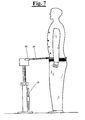
- Figure 7 and 8 show a body of a person in order to detail the using phases of the present device.
- the operator that has to take the measures places the device close to the body.
- By simply extracting or retracting the movable portion respect to the fixed one it is possible to place the supporting element 15 at the desired height.
- Particularly figure 8 shows a height signed by the reference bar 13.
- the graduated scale indicates the length.
- Figure 7 shows, only for convenience, the bar 13 placed back to the resting position in correspondence of the hook obtained on the base 4.
- the instrument is initially placed at the side of the person, or at the left or at the right.
- the bracket is thus removed by the specific magnetic hold support and inserted on top of said element 15.
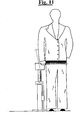
- the metre is wrapped around the pelvis of the person (look at figure 10 ).
- electronic saving devices as for example a computer, can allow to save directly the taken data on a CD in a way to store them until the cloth is made.
Landscapes
- Life Sciences & Earth Sciences (AREA)
- Biophysics (AREA)
- Engineering & Computer Science (AREA)
- Textile Engineering (AREA)
- Force Measurement Appropriate To Specific Purposes (AREA)
- Footwear And Its Accessory, Manufacturing Method And Apparatuses (AREA)
- Measurement Of The Respiration, Hearing Ability, Form, And Blood Characteristics Of Living Organisms (AREA)
Claims (10)
- Dispositif conçu pour prendre des mesures sur un corps d'une personne afin de réaliser un pantalon comprenant un bras (2) et des moyens (11, 13, 15, 18) de prise de mesure du pantalon, ledit bras (2) étant télescopique de façon à pouvoir s'étirer ou se rétracter de façon sélective et comprenant également un moyen (6) pour régler ledit bras (2) à une longueur choisie de façon à mettre en correspondance ladite longueur au travers desdits moyens (11, 13, 15, 18) avec la prise d'au moins une mesure sur le corps de la personne, dans lequel ledit bras (2) comprend une partie de base fixe (4) et au moins une partie supérieure (5) sélectivement étirable ou rétractable de/vers l'intérieur de ladite partie fixe, comportant également une échelle graduée (11) placée le long de ladite partie (5) et configurée de façon à indiquer la longueur atteinte en correspondance avec l'étirement ou la rétraction de ladite partie supérieure (5) par rapport à ladite partie de base fixe (4) et dans laquelle lesdits moyens (11, 13, 15, 18) pour prendre les mesures du pantalon comprennent un élément de support (15) placé en correspondance ou proche de l'extrémité supérieure de la partie supérieure (5), ledit élément de support (15) comprenant un dispositif (13, 14, 18, 19) qui permet de lire au moins une longueur et/ou une largeur du corps, ledit dispositif (13, 14, 18, 19) comprenant un levier de référence (13) qui indique, lors de l'utilisation, où se croisent les jambes du corps en correspondance avec ledit étirement ou ladite rétraction du bras (2), caractérisé en ce que ledit élément de support (15) comprend un crochet façonné (14) pour engager de façon amovible le levier de référence (13), et dans lequel ledit élément de support (15) comprend également un site (17) dans lequel est monté un compteur (18), le compteur (18) comportant une bande (19) avec un ressort interne d'enroulement automatique et configuré pour permettre de prendre la mesure d'une circonférence en correspondance avec la longueur choisie du bras (2), ledit site (17) étant positionné à une distance au-dessus du crochet façonné (14).
- Dispositif, selon la revendication 1, dans lequel ladite partie de base fixe (4) comprend une base de support (3) afin que ledit bras (2) puisse être placé sur le sol de façon à émerger vers le haut.
- Dispositif, selon la revendication 1, dans lequel ledit crochet (14) est de type magnétique et le levier (13) est métallique de façon à rester dans la position d'accrochage.
- Dispositif, selon la revendication 1, dans lequel ladite échelle graduée (11) est gravée sur ladite partie supérieure (5).
- Dispositif, selon une ou plusieurs des revendications précédentes, dans lequel ladite tête (15) comprend également un écran pour visualiser la mesure de longueur atteinte et un moyen de lecture électronique relié audit écran pour permettre au lecteur de lire ladite mesure.
- Dispositif, selon une ou plusieurs des revendications précédentes, dans lequel ledit compteur (18) est placé à une hauteur de 6,5 cm par rapport au positionnement dudit levier de référence (13) lorsque celui-ci est placé sur ledit élément de support (15).
- Dispositif, selon la revendication 1, dans lequel ledit site est fermé en haut par un couvercle supérieur (16) afin de retenir le compteur (18) à l'intérieur du site.
- Dispositif, selon les revendications 1 et 3, dans lequel la partie fixe (4) comprend un autre crochet (12) de façon à ce qu'une fois que la barre est utilisée, il soit possible de l'enlever par le crochet magnétique (14) sur l'élément de support (15) et à la placer en correspondance avec le crochet (12).
- Dispositif, selon l'une quelconque des revendications précédentes, dans lequel le levier de référence (13) comporte deux parties qui pivotent respectivement de façon à ce que le levier de référence puisse être configuré selon une forme substantiellement en I lorsqu'il se trouve en position fermée et une configuration en L en position d'utilisation lorsqu'il est inséré dans le crochet façonné.
- Dispositif conçu pour prendre des mesures sur un corps d'une personne afin de réaliser un pantalon comprenant un bras (2) et des moyens (11, 13, 15, 18) de prise de mesure du pantalon, ledit bras (2) étant télescopique de façon à pouvoir s'étirer ou se rétracter de façon sélective et comprenant également un moyen (6) pour régler ledit bras (2) à une longueur choisie de façon à mettre en correspondance ladite longueur au travers desdits moyens (11, 13, 15, 18) avec la prise d'au moins une mesure sur le corps, dans lequel ledit bras (2) comprend une partie de base fixe (4) et au moins une partie supérieure (5) sélectivement étirable ou rétractable de/vers l'intérieur de ladite partie fixe, comportant également une échelle graduée (11) placée le long de ladite partie (5) et configurée de façon à indiquer la longueur atteinte en correspondance avec l'étirement ou la rétraction de ladite partie supérieure (5) par rapport à ladite partie de base fixe (4) et lesdits moyens (11, 13, 15, 18) pour prendre les mesures du pantalon comprennent un élément de support (15) placé en correspondance ou proche de l'extrémité supérieure de la partie supérieure (5), ledit élément de support (15) comprenant un dispositif (13, 14, 18, 19) qui permet de lire au moins une longueur et/ou une largeur du corps, comprenant un levier de référence (13) qui indique, lors de l'utilisation, où se croisent les jambes du corps en correspondance avec ledit étirement ou ladite rétraction du bras, ledit levier de référence (13) étant intégré dans l'élément de support (15) et caractérisé en ce que ledit élément de support (15) comprend également un site (17) dans lequel est monté un compteur (18), le compteur (18) comportant une bande (19) avec un ressort interne d'enroulement automatique et configuré pour permettre de prendre la mesure d'une circonférence en correspondance avec la longueur choisie du bras (2), ledit site (17) étant positionné à une distance au-dessus du levier de référence (13).
Applications Claiming Priority (1)
| Application Number | Priority Date | Filing Date | Title |
|---|---|---|---|
| PCT/IT2009/000172 WO2010119463A1 (fr) | 2009-04-16 | 2009-04-16 | Dispositif de mesure de vêtement |
Publications (2)
| Publication Number | Publication Date |
|---|---|
| EP2418977A1 EP2418977A1 (fr) | 2012-02-22 |
| EP2418977B1 true EP2418977B1 (fr) | 2014-11-05 |
Family
ID=41404083
Family Applications (1)
| Application Number | Title | Priority Date | Filing Date |
|---|---|---|---|
| EP09787706.2A Not-in-force EP2418977B1 (fr) | 2009-04-16 | 2009-04-16 | Dispositif de mesure de vêtement |
Country Status (3)
| Country | Link |
|---|---|
| US (1) | US8756820B2 (fr) |
| EP (1) | EP2418977B1 (fr) |
| WO (1) | WO2010119463A1 (fr) |
Families Citing this family (5)
| Publication number | Priority date | Publication date | Assignee | Title |
|---|---|---|---|---|
| US8464391B2 (en) | 2007-04-03 | 2013-06-18 | Diversey, Inc. | Mop head fixation device and method |
| USD719712S1 (en) | 2012-09-07 | 2014-12-16 | Diversey, Inc. | Floor maintenance tool |
| US9696128B2 (en) * | 2013-11-01 | 2017-07-04 | Kurt Ott | Measuring accessory for tools |
| CN112515267A (zh) * | 2020-11-25 | 2021-03-19 | 广东元一科技实业有限公司 | 一种用于测量人体尺寸的装置 |
| EP4341639A4 (fr) * | 2021-05-14 | 2024-08-28 | Sea Ray Construction Llc | Outil de mesure de hauteur verticale |
Citations (2)
| Publication number | Priority date | Publication date | Assignee | Title |
|---|---|---|---|---|
| GB365836A (en) * | 1931-02-17 | 1932-01-28 | Domenico Caraceni | Improvements in or relating to measuring devices for wearing apparel |
| US3816925A (en) * | 1973-03-26 | 1974-06-18 | Rabone Chesterman Ltd | Tape measures |
Family Cites Families (17)
| Publication number | Priority date | Publication date | Assignee | Title |
|---|---|---|---|---|
| US177702A (en) * | 1876-05-23 | Improvement in tailors measures | ||
| US1168431A (en) * | 1912-10-31 | 1916-01-18 | Julius Schuman | Measuring instrument. |
| GB191510201A (en) * | 1915-07-13 | 1916-05-11 | Peter Falkivitch | A New or Improved Apparatus for Measuring and Facilitating the Measurement of the Human Form. |
| US2196145A (en) * | 1939-03-15 | 1940-04-02 | Stanziale Enrico | Marking device |
| US2246744A (en) | 1940-08-03 | 1941-06-24 | George K Manus | Tailor's measuring apparatus |
| US2645015A (en) | 1952-02-18 | 1953-07-14 | Orville W Zielaskowski | Device for taking inseam measurement of trousers |
| US2763062A (en) * | 1953-05-21 | 1956-09-18 | Daniel Eisenberg | Skirt marker |
| US2795852A (en) * | 1955-11-17 | 1957-06-18 | John B Ermilio | Tailor's measuring device |
| US2818648A (en) * | 1956-04-06 | 1958-01-07 | Jochheim Hans Rudolf August | Posture measuring device |
| US3031215A (en) * | 1958-12-11 | 1962-04-24 | Edward G Vance | Portable light |
| FR1404501A (fr) | 1964-04-28 | 1965-07-02 | Appareil justificateur de mesures complexes du corps humain pour la coupe des vêtements | |
| US3418717A (en) * | 1966-11-15 | 1968-12-31 | Irving L Wilson Company | Measuring apparatus |
| US3439424A (en) * | 1967-06-12 | 1969-04-22 | Irving L Wilson Co | Measuring apparatus |
| US5094418A (en) * | 1990-09-07 | 1992-03-10 | Stryker Corporation | IV pole |
| JPH08243089A (ja) * | 1995-03-13 | 1996-09-24 | Isamu Minami | ずれ量の測定機 |
| US6754974B2 (en) * | 2002-09-13 | 2004-06-29 | Antonio Bassolino | Distance-comparison device |
| AU2003287805A1 (en) * | 2002-12-02 | 2004-06-23 | Fernando Rego | Tailoring guide system |
-
2009
- 2009-04-16 EP EP09787706.2A patent/EP2418977B1/fr not_active Not-in-force
- 2009-04-16 WO PCT/IT2009/000172 patent/WO2010119463A1/fr not_active Ceased
- 2009-04-16 US US13/262,641 patent/US8756820B2/en not_active Expired - Fee Related
Patent Citations (2)
| Publication number | Priority date | Publication date | Assignee | Title |
|---|---|---|---|---|
| GB365836A (en) * | 1931-02-17 | 1932-01-28 | Domenico Caraceni | Improvements in or relating to measuring devices for wearing apparel |
| US3816925A (en) * | 1973-03-26 | 1974-06-18 | Rabone Chesterman Ltd | Tape measures |
Also Published As
| Publication number | Publication date |
|---|---|
| WO2010119463A1 (fr) | 2010-10-21 |
| EP2418977A1 (fr) | 2012-02-22 |
| US20120023764A1 (en) | 2012-02-02 |
| US8756820B2 (en) | 2014-06-24 |
Similar Documents
| Publication | Publication Date | Title |
|---|---|---|
| EP2418977B1 (fr) | Dispositif de mesure de vêtement | |
| US7685727B2 (en) | Measuring device for garment tailoring, and related methods | |
| JP4579476B2 (ja) | 陳列スタンド | |
| US6813838B2 (en) | Garment fitting system | |
| US2053810A (en) | Measuring apparatus | |
| US20040107593A1 (en) | Tailoring guide system | |
| US7249423B2 (en) | Measuring device for garment tailoring, and related methods | |
| US7832569B1 (en) | Adjustable clothing display rack | |
| US2016967A (en) | Golf bag support | |
| CN103348224B (zh) | 便携式行李计量器 | |
| US12185783B1 (en) | Device and method for determining garment size | |
| CN213431120U (zh) | 一种辅助穿衣轮椅 | |
| CN205642583U (zh) | 一种身体尺寸和重量测量装置 | |
| US2112928A (en) | Inseam measuring device | |
| US4674189A (en) | Tailor's marker and method | |
| CN112515267A (zh) | 一种用于测量人体尺寸的装置 | |
| CN111264952B (zh) | 一种用于西服服装设计的快速测量的辅助装置 | |
| CN114271570A (zh) | 一种服装设计用可折叠测量体型装置 | |
| US2509723A (en) | Girdle drier | |
| CN221180251U (zh) | 酱油盐分警示装置 | |
| US2534757A (en) | Dress form | |
| KR20230079316A (ko) | 신체 치수 측정이 용이한 t형 줄자 | |
| KR200481680Y1 (ko) | 회전식 손잡이를 갖는 우산 | |
| US1037058A (en) | Tailor's measuring apparatus. | |
| JP5800142B2 (ja) | オーダーメイドのための上衣ゲージ服 |
Legal Events
| Date | Code | Title | Description |
|---|---|---|---|
| PUAI | Public reference made under article 153(3) epc to a published international application that has entered the european phase |
Free format text: ORIGINAL CODE: 0009012 |
|
| 17P | Request for examination filed |
Effective date: 20111024 |
|
| AK | Designated contracting states |
Kind code of ref document: A1 Designated state(s): AT BE BG CH CY CZ DE DK EE ES FI FR GB GR HR HU IE IS IT LI LT LU LV MC MK MT NL NO PL PT RO SE SI SK TR |
|
| DAX | Request for extension of the european patent (deleted) | ||
| 17Q | First examination report despatched |
Effective date: 20120802 |
|
| GRAP | Despatch of communication of intention to grant a patent |
Free format text: ORIGINAL CODE: EPIDOSNIGR1 |
|
| INTG | Intention to grant announced |
Effective date: 20131112 |
|
| GRAS | Grant fee paid |
Free format text: ORIGINAL CODE: EPIDOSNIGR3 |
|
| GRAA | (expected) grant |
Free format text: ORIGINAL CODE: 0009210 |
|
| AK | Designated contracting states |
Kind code of ref document: B1 Designated state(s): AT BE BG CH CY CZ DE DK EE ES FI FR GB GR HR HU IE IS IT LI LT LU LV MC MK MT NL NO PL PT RO SE SI SK TR |
|
| REG | Reference to a national code |
Ref country code: GB Ref legal event code: FG4D |
|
| REG | Reference to a national code |
Ref country code: CH Ref legal event code: EP |
|
| REG | Reference to a national code |
Ref country code: AT Ref legal event code: REF Ref document number: 694111 Country of ref document: AT Kind code of ref document: T Effective date: 20141115 |
|
| REG | Reference to a national code |
Ref country code: IE Ref legal event code: FG4D |
|
| REG | Reference to a national code |
Ref country code: DE Ref legal event code: R096 Ref document number: 602009027607 Country of ref document: DE Effective date: 20141218 |
|
| REG | Reference to a national code |
Ref country code: AT Ref legal event code: MK05 Ref document number: 694111 Country of ref document: AT Kind code of ref document: T Effective date: 20141105 |
|
| REG | Reference to a national code |
Ref country code: NL Ref legal event code: VDEP Effective date: 20141105 |
|
| REG | Reference to a national code |
Ref country code: LT Ref legal event code: MG4D |
|
| PG25 | Lapsed in a contracting state [announced via postgrant information from national office to epo] |
Ref country code: ES Free format text: LAPSE BECAUSE OF FAILURE TO SUBMIT A TRANSLATION OF THE DESCRIPTION OR TO PAY THE FEE WITHIN THE PRESCRIBED TIME-LIMIT Effective date: 20141105 Ref country code: NO Free format text: LAPSE BECAUSE OF FAILURE TO SUBMIT A TRANSLATION OF THE DESCRIPTION OR TO PAY THE FEE WITHIN THE PRESCRIBED TIME-LIMIT Effective date: 20150205 Ref country code: NL Free format text: LAPSE BECAUSE OF FAILURE TO SUBMIT A TRANSLATION OF THE DESCRIPTION OR TO PAY THE FEE WITHIN THE PRESCRIBED TIME-LIMIT Effective date: 20141105 Ref country code: FI Free format text: LAPSE BECAUSE OF FAILURE TO SUBMIT A TRANSLATION OF THE DESCRIPTION OR TO PAY THE FEE WITHIN THE PRESCRIBED TIME-LIMIT Effective date: 20141105 Ref country code: IS Free format text: LAPSE BECAUSE OF FAILURE TO SUBMIT A TRANSLATION OF THE DESCRIPTION OR TO PAY THE FEE WITHIN THE PRESCRIBED TIME-LIMIT Effective date: 20150305 Ref country code: LT Free format text: LAPSE BECAUSE OF FAILURE TO SUBMIT A TRANSLATION OF THE DESCRIPTION OR TO PAY THE FEE WITHIN THE PRESCRIBED TIME-LIMIT Effective date: 20141105 Ref country code: PT Free format text: LAPSE BECAUSE OF FAILURE TO SUBMIT A TRANSLATION OF THE DESCRIPTION OR TO PAY THE FEE WITHIN THE PRESCRIBED TIME-LIMIT Effective date: 20150305 |
|
| PG25 | Lapsed in a contracting state [announced via postgrant information from national office to epo] |
Ref country code: SE Free format text: LAPSE BECAUSE OF FAILURE TO SUBMIT A TRANSLATION OF THE DESCRIPTION OR TO PAY THE FEE WITHIN THE PRESCRIBED TIME-LIMIT Effective date: 20141105 Ref country code: GR Free format text: LAPSE BECAUSE OF FAILURE TO SUBMIT A TRANSLATION OF THE DESCRIPTION OR TO PAY THE FEE WITHIN THE PRESCRIBED TIME-LIMIT Effective date: 20150206 Ref country code: AT Free format text: LAPSE BECAUSE OF FAILURE TO SUBMIT A TRANSLATION OF THE DESCRIPTION OR TO PAY THE FEE WITHIN THE PRESCRIBED TIME-LIMIT Effective date: 20141105 Ref country code: LV Free format text: LAPSE BECAUSE OF FAILURE TO SUBMIT A TRANSLATION OF THE DESCRIPTION OR TO PAY THE FEE WITHIN THE PRESCRIBED TIME-LIMIT Effective date: 20141105 Ref country code: HR Free format text: LAPSE BECAUSE OF FAILURE TO SUBMIT A TRANSLATION OF THE DESCRIPTION OR TO PAY THE FEE WITHIN THE PRESCRIBED TIME-LIMIT Effective date: 20141105 Ref country code: PL Free format text: LAPSE BECAUSE OF FAILURE TO SUBMIT A TRANSLATION OF THE DESCRIPTION OR TO PAY THE FEE WITHIN THE PRESCRIBED TIME-LIMIT Effective date: 20141105 Ref country code: CY Free format text: LAPSE BECAUSE OF FAILURE TO SUBMIT A TRANSLATION OF THE DESCRIPTION OR TO PAY THE FEE WITHIN THE PRESCRIBED TIME-LIMIT Effective date: 20141105 |
|
| PG25 | Lapsed in a contracting state [announced via postgrant information from national office to epo] |
Ref country code: CZ Free format text: LAPSE BECAUSE OF FAILURE TO SUBMIT A TRANSLATION OF THE DESCRIPTION OR TO PAY THE FEE WITHIN THE PRESCRIBED TIME-LIMIT Effective date: 20141105 Ref country code: RO Free format text: LAPSE BECAUSE OF FAILURE TO SUBMIT A TRANSLATION OF THE DESCRIPTION OR TO PAY THE FEE WITHIN THE PRESCRIBED TIME-LIMIT Effective date: 20141105 Ref country code: SK Free format text: LAPSE BECAUSE OF FAILURE TO SUBMIT A TRANSLATION OF THE DESCRIPTION OR TO PAY THE FEE WITHIN THE PRESCRIBED TIME-LIMIT Effective date: 20141105 Ref country code: EE Free format text: LAPSE BECAUSE OF FAILURE TO SUBMIT A TRANSLATION OF THE DESCRIPTION OR TO PAY THE FEE WITHIN THE PRESCRIBED TIME-LIMIT Effective date: 20141105 Ref country code: DK Free format text: LAPSE BECAUSE OF FAILURE TO SUBMIT A TRANSLATION OF THE DESCRIPTION OR TO PAY THE FEE WITHIN THE PRESCRIBED TIME-LIMIT Effective date: 20141105 |
|
| REG | Reference to a national code |
Ref country code: DE Ref legal event code: R097 Ref document number: 602009027607 Country of ref document: DE |
|
| PLBE | No opposition filed within time limit |
Free format text: ORIGINAL CODE: 0009261 |
|
| STAA | Information on the status of an ep patent application or granted ep patent |
Free format text: STATUS: NO OPPOSITION FILED WITHIN TIME LIMIT |
|
| 26N | No opposition filed |
Effective date: 20150806 |
|
| PG25 | Lapsed in a contracting state [announced via postgrant information from national office to epo] |
Ref country code: LU Free format text: LAPSE BECAUSE OF FAILURE TO SUBMIT A TRANSLATION OF THE DESCRIPTION OR TO PAY THE FEE WITHIN THE PRESCRIBED TIME-LIMIT Effective date: 20150416 Ref country code: MC Free format text: LAPSE BECAUSE OF FAILURE TO SUBMIT A TRANSLATION OF THE DESCRIPTION OR TO PAY THE FEE WITHIN THE PRESCRIBED TIME-LIMIT Effective date: 20141105 |
|
| REG | Reference to a national code |
Ref country code: CH Ref legal event code: PL |
|
| REG | Reference to a national code |
Ref country code: IE Ref legal event code: MM4A |
|
| PG25 | Lapsed in a contracting state [announced via postgrant information from national office to epo] |
Ref country code: CH Free format text: LAPSE BECAUSE OF NON-PAYMENT OF DUE FEES Effective date: 20150430 Ref country code: LI Free format text: LAPSE BECAUSE OF NON-PAYMENT OF DUE FEES Effective date: 20150430 |
|
| PG25 | Lapsed in a contracting state [announced via postgrant information from national office to epo] |
Ref country code: SI Free format text: LAPSE BECAUSE OF FAILURE TO SUBMIT A TRANSLATION OF THE DESCRIPTION OR TO PAY THE FEE WITHIN THE PRESCRIBED TIME-LIMIT Effective date: 20141105 |
|
| REG | Reference to a national code |
Ref country code: FR Ref legal event code: PLFP Year of fee payment: 8 |
|
| PG25 | Lapsed in a contracting state [announced via postgrant information from national office to epo] |
Ref country code: IE Free format text: LAPSE BECAUSE OF NON-PAYMENT OF DUE FEES Effective date: 20150416 |
|
| PG25 | Lapsed in a contracting state [announced via postgrant information from national office to epo] |
Ref country code: MT Free format text: LAPSE BECAUSE OF FAILURE TO SUBMIT A TRANSLATION OF THE DESCRIPTION OR TO PAY THE FEE WITHIN THE PRESCRIBED TIME-LIMIT Effective date: 20141105 |
|
| REG | Reference to a national code |
Ref country code: FR Ref legal event code: PLFP Year of fee payment: 9 |
|
| PG25 | Lapsed in a contracting state [announced via postgrant information from national office to epo] |
Ref country code: BG Free format text: LAPSE BECAUSE OF FAILURE TO SUBMIT A TRANSLATION OF THE DESCRIPTION OR TO PAY THE FEE WITHIN THE PRESCRIBED TIME-LIMIT Effective date: 20141105 Ref country code: HU Free format text: LAPSE BECAUSE OF FAILURE TO SUBMIT A TRANSLATION OF THE DESCRIPTION OR TO PAY THE FEE WITHIN THE PRESCRIBED TIME-LIMIT; INVALID AB INITIO Effective date: 20090416 |
|
| PGFP | Annual fee paid to national office [announced via postgrant information from national office to epo] |
Ref country code: GB Payment date: 20170406 Year of fee payment: 9 |
|
| PG25 | Lapsed in a contracting state [announced via postgrant information from national office to epo] |
Ref country code: TR Free format text: LAPSE BECAUSE OF FAILURE TO SUBMIT A TRANSLATION OF THE DESCRIPTION OR TO PAY THE FEE WITHIN THE PRESCRIBED TIME-LIMIT Effective date: 20141105 |
|
| PG25 | Lapsed in a contracting state [announced via postgrant information from national office to epo] |
Ref country code: BE Free format text: LAPSE BECAUSE OF FAILURE TO SUBMIT A TRANSLATION OF THE DESCRIPTION OR TO PAY THE FEE WITHIN THE PRESCRIBED TIME-LIMIT Effective date: 20141105 |
|
| PG25 | Lapsed in a contracting state [announced via postgrant information from national office to epo] |
Ref country code: MK Free format text: LAPSE BECAUSE OF FAILURE TO SUBMIT A TRANSLATION OF THE DESCRIPTION OR TO PAY THE FEE WITHIN THE PRESCRIBED TIME-LIMIT Effective date: 20141105 |
|
| REG | Reference to a national code |
Ref country code: FR Ref legal event code: PLFP Year of fee payment: 10 |
|
| GBPC | Gb: european patent ceased through non-payment of renewal fee |
Effective date: 20180416 |
|
| PG25 | Lapsed in a contracting state [announced via postgrant information from national office to epo] |
Ref country code: GB Free format text: LAPSE BECAUSE OF NON-PAYMENT OF DUE FEES Effective date: 20180416 |
|
| PGFP | Annual fee paid to national office [announced via postgrant information from national office to epo] |
Ref country code: IT Payment date: 20210319 Year of fee payment: 13 |
|
| PGFP | Annual fee paid to national office [announced via postgrant information from national office to epo] |
Ref country code: FR Payment date: 20210419 Year of fee payment: 13 Ref country code: DE Payment date: 20210416 Year of fee payment: 13 |
|
| REG | Reference to a national code |
Ref country code: DE Ref legal event code: R119 Ref document number: 602009027607 Country of ref document: DE |
|
| PG25 | Lapsed in a contracting state [announced via postgrant information from national office to epo] |
Ref country code: FR Free format text: LAPSE BECAUSE OF NON-PAYMENT OF DUE FEES Effective date: 20220430 Ref country code: DE Free format text: LAPSE BECAUSE OF NON-PAYMENT OF DUE FEES Effective date: 20221103 |
|
| PG25 | Lapsed in a contracting state [announced via postgrant information from national office to epo] |
Ref country code: IT Free format text: LAPSE BECAUSE OF NON-PAYMENT OF DUE FEES Effective date: 20220416 |