EP2419246B1 - Actuateur avec des éléments du type cable ou courroie - Google Patents
Actuateur avec des éléments du type cable ou courroie Download PDFInfo
- Publication number
- EP2419246B1 EP2419246B1 EP10708936.9A EP10708936A EP2419246B1 EP 2419246 B1 EP2419246 B1 EP 2419246B1 EP 10708936 A EP10708936 A EP 10708936A EP 2419246 B1 EP2419246 B1 EP 2419246B1
- Authority
- EP
- European Patent Office
- Prior art keywords
- shaft
- rope
- actuator
- unit
- ropes
- Prior art date
- Legal status (The legal status is an assumption and is not a legal conclusion. Google has not performed a legal analysis and makes no representation as to the accuracy of the status listed.)
- Not-in-force
Links
Images


Classifications
-
- B—PERFORMING OPERATIONS; TRANSPORTING
- B25—HAND TOOLS; PORTABLE POWER-DRIVEN TOOLS; MANIPULATORS
- B25J—MANIPULATORS; CHAMBERS PROVIDED WITH MANIPULATION DEVICES
- B25J9/00—Program-controlled manipulators
- B25J9/10—Program-controlled manipulators characterised by positioning means for manipulator elements
- B25J9/104—Program-controlled manipulators characterised by positioning means for manipulator elements with cables, chains or ribbons
-
- B—PERFORMING OPERATIONS; TRANSPORTING
- B25—HAND TOOLS; PORTABLE POWER-DRIVEN TOOLS; MANIPULATORS
- B25J—MANIPULATORS; CHAMBERS PROVIDED WITH MANIPULATION DEVICES
- B25J18/00—Arms
- B25J18/02—Arms extensible
- B25J18/04—Arms extensible rotatable
-
- B—PERFORMING OPERATIONS; TRANSPORTING
- B25—HAND TOOLS; PORTABLE POWER-DRIVEN TOOLS; MANIPULATORS
- B25J—MANIPULATORS; CHAMBERS PROVIDED WITH MANIPULATION DEVICES
- B25J9/00—Program-controlled manipulators
- B25J9/10—Program-controlled manipulators characterised by positioning means for manipulator elements
- B25J9/12—Program-controlled manipulators characterised by positioning means for manipulator elements electric
- B25J9/126—Rotary actuators
-
- F—MECHANICAL ENGINEERING; LIGHTING; HEATING; WEAPONS; BLASTING
- F16—ENGINEERING ELEMENTS AND UNITS; GENERAL MEASURES FOR PRODUCING AND MAINTAINING EFFECTIVE FUNCTIONING OF MACHINES OR INSTALLATIONS; THERMAL INSULATION IN GENERAL
- F16H—GEARING
- F16H19/00—Gearings comprising essentially only toothed gears or friction members and not capable of conveying indefinitely-continuing rotary motion
- F16H19/02—Gearings comprising essentially only toothed gears or friction members and not capable of conveying indefinitely-continuing rotary motion for interconverting rotary or oscillating motion and reciprocating motion
- F16H19/06—Gearings comprising essentially only toothed gears or friction members and not capable of conveying indefinitely-continuing rotary motion for interconverting rotary or oscillating motion and reciprocating motion comprising flexible members, e.g. an endless flexible member
- F16H19/0618—Gearings comprising essentially only toothed gears or friction members and not capable of conveying indefinitely-continuing rotary motion for interconverting rotary or oscillating motion and reciprocating motion comprising flexible members, e.g. an endless flexible member the flexible member, e.g. cable, being wound on a drum or thread for creating axial movement parallel to the drum or thread
Definitions
- the invention relates to an actuator with a shaft drive rotating shaft drive to the shaft at least two band or rope-like elements, hereinafter referred to as "ropes" called with two cable ends, depending on the direction of shaft rotation and unwound, each of which the first end of the rope is connected to a cable attachment along the shaft and the cable attachment locations of both first cable ends are axially spaced along the shaft, and each of which the second cable ends are in operative connection with a first actuator such that the cables between the shaft and the first actuator unit always run smoothly, by winding the first cable onto the shaft, the first actuator unit performs a rotational and / or translational first movement while the second cable unwinds from the shaft, and by winding the second cable onto the shaft, the first Actuator one for the first movement to reversed motion as the first rope unwinds from the shaft.
- ropes called with two cable ends, depending on the direction of shaft rotation and unwound, each of which the first end of the rope is connected to a cable attachment along the shaft and the cable attachment
- Actuators for the transmission of tensile forces for example between a mechanical fixed abutment and a relative to the abutment movably mounted object, are known in manifold variety.
- a very simple embodiment of such an actuator is a connected to a fixed abutment, motor-driven shaft is wound around the traction means a rope which is wound or unwound with a corresponding shaft rotation on the shaft. If the loose end of the rope, for example, firmly connected to an otherwise loosely mounted object, so is by the motor-assisted Rope winding pulled the object in the direction of the fixed abutment.
- a disadvantage of such actuator training is the direct load on the shaft, which is suitable to form stable and / or stable storage.
- Such cable pull actuators are used in the field of mechanical drive technology in a variety of embodiments for driving or for locomotion of kinematic systems.
- one or the other cable is wound onto the shaft, which along the cable wound on the rope rope forming tensile force sets the pair of rollers in rotation, by which the lever arm is deflected kraftbeetzschlagt.
- the lever arm can be deflected by means of the same mechanism of action in the opposite direction of pivoting by reversing the action of rotation and force.
- the object is to provide a based on the above bidirectional actuator principle actuator to be placed on the much lower requirements in terms of mechanical load requirements and robustness in terms of training and storage of the shaft drive.
- the novel actuator should have the highest degree of integration capability in mechanically complex systems and, in addition, should be almost infinitely miniaturizable. With the help of the novel actuator kinematic and capable of locomotion systems should be feasible with the simplest possible and cost-effective means that are particularly applicable and applicable in the field of prosthetics and arbitrarily articulated robot kinematics.
- the rope section directly tapering to the shaft always includes a constant winding angle with the shaft.
- the unwinding of the rope from the shaft ie taking place in the direction of the first deflection Seilabwicklung also always takes place at a constant winding angle, which includes the directly from the shaft unwinding rope course with the axial Lijnsverstreckung the shaft.
- the axial positional shift of the first deflection unit coordinated with the winding speed, ensures a constant cable pull along both cables.
- the axial relative position of the first deflection unit with respect to the cable attachment locations along the shaft is selected such that the deflection unit is arranged in the middle between the two cable attachment locations in projection to the shaft axis, provided in each case the same or approximately the same cable length adjacent to both cable attachment locations is wound up on the shaft.
- the respective second cable ends of the third and fourth cables are operatively connected to the first and / or a second actuator unit in such a way that the third and fourth cables always run tightly between the shaft and the first and / or second actuator unit, by winding up the third cable on the shaft, the first and / or second actuator unit performs a rotational and / or translational first movement, while the fourth cable unwinds from the shaft, and by winding the fourth cable onto the shaft, the first and / or second actuator unit for a first movement reverse movement while the third rope unwinds from the shaft.
- At least one second deflection unit is provided, which is arranged at an orthogonal distance to the shaft and in orthogonal projection on the shaft between the two cable attachment locations axially movable relative to the shaft, the diametrically the first deflecting relative to the shaft opposite and over which the third and fourth rope for direct winding or unwinding are forced to or from the shaft.
- first and second rope can also be replaced by a single, continuous rope, the two rope ends of which are fastened along the shaft at the rope attachment points described.
- the first actuator unit is in this case with a, preferably middle cable section along the single rope in operative connection to be deflected by this, depending on the direction of shaft rotation.
- third and fourth rope which may be formed in the form of a single rope in the manner explained above.
- the cable end guided via the first actuator unit and in operative connection with the second actuator unit is linked to its other cable end, which is connected to the second actuator unit.
- the tensile forces acting along the cables on the shaft can be completely compensated for each other, so that the shaft can bear force-free or substantially force-free, so that the shaft easy and small, ie. can be formed in particular with a small shaft diameter. Also, there are no major mechanical requirements in terms of storage and strength of the shaft drive.
- the total mass of a system operated with the structure according to the solution is significantly reduced, since neither two actuators are required for one degree of freedom and, on the other hand, the shaft and the rotary drive can be made lightweight and compact.
- the shaft and the rotary drive can be made lightweight and compact.
- the actuator according to the invention can be encapsulated with a suitably designed housing, so that only an electrical supply line and the respective cables protrude from such a "black box structure", which is particularly suitable for the use of any kinematics movements, be it translational and / or. or rotational movements and this with the application of high motional forces.
- the actuator according to the invention can also be formed along the shaft with further deflecting units arranged diametrically to the shaft with the associated cable pulls, which can serve, for example, for controlling the motion of further actuator units. In this way, the variety of functions can be increased with simultaneous miniaturization.
- the participating cables of the actuator according to the invention from two or more cable strands or rope fibers, each run together per cable via the corresponding deflection and up or unwound as a unitary cable on the shaft or shaft become.
- Each individual strand of rope or each individual stranded fiber can run away from the deflecting unit shaft-facing to different actuator units and deflect them accordingly.
- FIG. 1 is the left image representation, the top view of a solution designed according to actuator unit shown, which provides a fixed space arranged wave drive 1 with a shaft 1 ', which ends free end in the illustrated embodiment.
- the shaft drive 1 is typically designed as an electric motor with gear stage, and is infinitely variable in relation to the speed.
- a first cable S1 which is wound in a helical, single-layer winding in the illustrated manner around the shaft 1', is fastened to a first cable attachment location 5.
- the cable S1 leads starting from the shaft 1 'at a winding angle ⁇ directly to a deflecting roller 7 formed as a deflection roller, from which the cable S1 comes into operative connection with an actuator unit 8 designed as a disk.
- the disc 8 is rotatably mounted about a rotation axis D and has a peripheral disc edge around which at least partially the rope S1 is applied to form a frictional engagement. Furthermore, after at least half a wrapping around the disc edge of the disc 8, the rope S1 runs back to the deflecting roller 7 and nestles around the shaft 2 in the region of the second cable attachment location 6, likewise forming a few single-layered helical cable windings. Both ends of the rope S1 are connected to the cable attachment locations 5 and 6 fixed to the shaft 1 '.
- the cable S1 is integrally formed and in the manner described above with the disk-shaped actuator unit 8 in operative connection.
- two separate cables are connected to the disk-shaped actuator unit 8, wherein a first cable is connected on the one hand to the cable attachment location 5 and on the other hand to the disk-shaped actuator unit 8 and a second cable on the one hand with the shaft at the cable attachment location 6 and on the other hand with the disk-shaped actuator unit.
- a second deflection unit 9 is provided in mirror image to the shaft 1', around which a second cable S2 is guided, whose cable ends are fastened in the same way to the cable mounting bearings 5 and 6 and its on the shaft.
- 1 'coiled cable sections with those of the first rope S1 form a doppelhelikal, single-layer Aufwickelmuster.
- the second deflection unit 9 is axially movably guided along the shaft 1 ', so that the cable sections directed onto the shaft 1' by the second deflection unit 9 also remain constant over the entire unwinding and winding process Include ⁇ .
- the second cable S2 surrounds a second disk-shaped actuator unit 8 ', which is rotatably mounted together with the first actuator unit 8 about the rotation axis D.
- a worm gear 2 is mounted, which is in engagement with a rack 3, which is fixedly connected to the deflecting units 7, 9.
- a linear guide 4 are at shaft rotation, the rack 3 and the deflecting units 7, 9 axially deflected to the shaft 1 ', whereby the Seilauf- and development of both cables S1, S2 on or from the shaft in a controlled manner while maintaining a constant winding angle ⁇ can be done, ultimately with the aim of forming a single-layer double helical winding pattern around the shaft 1 '.
- the disk-shaped actuator units 8, 8 ' are shown in a side view.
- the deflecting units 7, 9 shown in the side view are arranged slightly offset from one another; in fact, when viewed from the side, they coincide to allow complete compensation of the tensile forces acting on the shaft 1 'by the rope forces.
- the second completely continuous rope S2 can also be replaced by two separate ropes in the manner described above.
- the disk-shaped actuator unit 8, 8 'illustrated in the exemplary embodiment are merely representative of a multiplicity of possible actuators displaceable in rotation and / or in translatory motion; for example, it is also possible to connect the cable sections connected to the actuator unit to two lever arms mounted about a pivot axis connect to.
- there are no limits to a further embodiment of the actuator unit for example only it should be mentioned that to the in FIG. 1 shown disk-like actuator units 8, 8 'each a pivot arm can be joined, which is bidirectionally pivotable about the axis of rotation D.
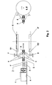
- FIG. 2 the already denote FIG. 1 explained reference numerals identical components, the repeated description is omitted.
- the deflecting units 7, 9 are fixed in space.
- the shaft drive 1 together with shaft 1 'arranged on a linear guide 4 axially movable.
- the axial deflection of the shaft drive 1 and the associated shaft 1 ' via an engagement of a fixed space arranged rack 3 with the attached to the shaft 2 worm gear structure 2. If the shaft 1' set in rotation, the shaft 1 'moves relative to the space fixed deflecting units 7, 9 are, for example, the in FIG.
- FIG. 3 a third variant of an embodiment of the actuator according to the invention is explained, in which both the deflection units 7, 9 and the shaft drive 1 are mounted fixed in space.
- the shaft 1' is formed as a hollow shaft and communicates with the actual drive shaft 10 of the shaft drive 1 in a rotationally fixed operative connection nonetheless Hollow shaft 1 'axially movable to the drive shaft 10 is mounted.
- a fixed space arranged rack 4 which is in engagement with a mounted on the hollow shaft 1 'helical gear structure 2, the hollow shaft 1' together with the wound thereon cable sections corresponding to the direction of rotation and rotational speed axially deflected.
Landscapes
- Engineering & Computer Science (AREA)
- Mechanical Engineering (AREA)
- Robotics (AREA)
- General Engineering & Computer Science (AREA)
- Transmission Devices (AREA)
Claims (17)
- Actionneur avec un système d'entraînement à arbre (1) mettant en rotation un arbre (1'), autour de l'arbre (1') duquel au moins deux éléments de type bande ou câble, désignés ci-après à chaque fois par « câbles », avec à chaque fois deux extrémités de câble sont enroulables et déroulables en fonction du sens de rotation de l'arbre, dont à chaque fois la première extrémité de câble est reliée à un point de fixation de câble (5, 6) le long de l'arbre (1') et les points de fixation de câble (5, 6) des deux premières extrémités de câble sont éloignés l'un de l'autre axialement lé long de l'arbre (1') et dont à chaque fois les deux extrémités de câble sont en liaison active avec une première unité d'actionneur (8) de telle sorte que les câbles passent toujours tendus entre l'arbre (1') et la première unité d'actionneur (8), la première unité d'actionneur (8) effectuant par enroulement du premier câble sur l'arbre (1') un premier mouvement rotatoire et/ou translatoire, pendant que le deuxième câble se déroule de l'arbre (1') et que la première unité d'actionneur effectue un mouvement inversé au premier mouvement par enroulement du deuxième câble sur l'arbre (1'), pendant que le premier câble se déroule de l'arbre (1') caractérisé en ce qu'une première unité de renvoi (7) est prévue qui est montée de façon mobile dans le sens axial par rapport à l'arbre (1') avec un intervalle orthogonal par rapport à l'arbre (1') ainsi qu'en projection orthogonale sur l'arbre (1') entre les deux points de fixation de câble (5, 6) et par laquelle le premier et le deuxième câble sont en guidage forcé pour l'enroulement ou le déroulement direct sur ou depuis l'arbre (1'), et en ce que la première extrémité de câble d'un troisième câble dans la zone d'un point de fixation de câble (5) et une première extrémité de câble d'un quatrième câble dans la zone de l'autre point de fixation de câble (6) sont reliées à l'arbre (1'), en ce qu'à chaque fois les deuxièmes extrémités de câble du troisième et quatrième câble sont en liaison active avec la première et/ou la deuxième unité d'actionneur (8') de telle sorte que le troisième et le quatrième câble passent entre l'arbre (1') et la première et/ou deuxième unité d'actionneur (8') toujours tendus, la première et/ou la deuxième unité d'actionneur (8, 8') effectuant par enroulement du troisième câble sur l'arbre (1') un premier mouvement rotatoire et/ou translatoire, pendant que le quatrième câble se déroule de l'arbre (1') et la première et/ou la deuxième unité d'actionneur (8, 8') effectuant par enroulement du quatrième câble sur l'arbre (1') un mouvement inversé par rapport au premier mouvement pendant que le troisième câble se déroule de l'arbre (1'), en ce qu'une deuxième unité de renvoi (9) est prévue qui est montée de façon mobile dans le sens axial par rapport à l'arbre (1') avec un intervalle orthogonal par rapport à l'arbre (1') ainsi qu'en projection orthogonale sur l'arbre (1') entre les deux points de fixation de câble (5, 6), qui est diamétralement opposée à la première unité de renvoi (7) par rapport à l'arbre (1') et par laquelle le troisième et le quatrième câble sont en guidage forcé pour l'enroulement ou le déroulement direct sur ou depuis l'arbre (1'),
- Actionneur selon la revendication 1 caractérisé en ce que le premier et le deuxième câble sont constitués comme un premier câble (S1) traversant et le troisième et quatrième câble comme un deuxième câble (S2) traversant et en ce que les extrémités de câble du premier câble traversant (S1) sont reliées à l'arbre (1') aux deux points de fixation de câble (5, 6) et le premier câble (S1) traversant est en liaison active avec la première unité d'actionneur (8), en ce que les extrémités de câble du deuxième câble (S2) traversant sont reliées à l'arbre (1') aux deux points de fixation de câble (5, 6) et le deuxième câble (S2) traversant est en liaison active avec la deuxième unité d'actionneur (8').
- Actionneur selon la revendication 1 caractérisé en ce que le premier et le troisième câble sont constitués comme un premier câble traversant et le deuxième et quatrième câble comme un deuxième câble (S2) traversant, en ce que les extrémités de câble du premier câble (S1) traversant sont à chaque fois reliées avec la première et la deuxième unité d'actionneur (8, 8') et la zone centrale du premier câble (S1) traversant est reliée à l'arbre (1') à un point de fixation de câble (5) et en ce que les extrémités de câble du deuxième câble (S2) traversant sont à chaque fois reliées avec la première et la deuxième unités d'actionneur (8, 8') et la zone centrale du deuxième câble (S2) traversant à l'arbre (1') à l'autre point de fixation de câble (6).
- Actionneur selon la revendication 1 caractérisé en ce que le premier et le troisième câble sont constitués comme un premier câble (S1) traversant et le deuxième et quatrième câble comme un deuxième câble (S2) traversant, en ce que les extrémités de câble du premier câble (S1) traversant sont en liaison active à chaque fois avec la première et la deuxième unités d'actionneur (8, 8') et la zone centrale du premier câble (S1) traversant est reliée à l'arbre (1') à un point de fixation de câble (5) et en ce que les extrémités de câble du deuxième câble (S2) traversant sont en liaison active à chaque fois avec la première et la deuxième unité d'actionneur (8, 8') et la zone centrale du deuxième câble (S2) traversant est reliée à l'arbre (1'), à l'autre point de fixation de câble (6).
- Actionneur selon une quelconque des revendications 1 à 4 caractérisé en ce que la première et la deuxième unité de renvoi (7, 9) sont guidées de façon mobile dans le sens axial par rapport à l'arbre (1') de telle sorte que les câbles peuvent à chaque fois être enroulés et déroulés sur l'arbre (1') avec un angle d'enroulement α constant, avec α différent de 90°.
- Actionneur selon une quelconque des revendications 1 à 5 caractérisé en ce que la première et la deuxième unité de renvoi (7, 9) sont guidées de façon mobile dans le sens axial par rapport à l'arbre (1') de telle sorte que les câbles montés à chaque fois dans la zone d'un point de fixation de câble (5, 6) adoptent, pendant l'enroulement et le déroulement, une position d'enroulement à une couche, à double hélice, entrelacés l'un dans l'autre le long de l'arbre (1').
- Actionneur selon une quelconque des revendications 1 à 6 caractérisé en ce que le système d'entraînement d'arbre (1) et l'arbre (1') sont montés stabilisés et la première et la deuxième unité de renvoi (7, 9) sont montées de façon mobile dans le sens axial par rapport à l'arbre (1') stabilisé.
- Actionneur selon la revendication 7 caractérisé en ce qu'un système de transmission en prise avec l'arbre (1') transforme la rotation de l'arbre en un mouvement linéaire axialement orienté auquel sont couplées la première et la deuxième unité de renvoi (7, 9).
- Actionneur selon une quelconque des revendications 1 à 6 caractérisé en ce que le système d'entraînement d'arbre (1) et l'arbre (1') sont montés de façon mobile dans le sens axial et la première et la deuxième unité de renvoi (7, 9) sont montées de façon stabilisée.
- Actionneur selon la revendication 9 caractérisé en ce qu'un système de transmission en prise avec l'arbre (1') transforme la rotation de l'arbre en un mouvement linéaire orienté axialement auquel sont couplés le système d'entraînement d'arbre et l'arbre.
- Actionneur selon une quelconque des revendications 1 à 6 caractérisé en ce que le système d'entraînement d'arbre (1) et la première et la deuxième unité de renvoi (7, 9) montés de façon stabilisée et l'arbre (1') sont constitués de façon mobile dans le sens axial.
- Actionneur selon la revendication 11 caractérisé en ce que l'arbre (1') est constitué en deux parties, présente une première partie d'arbre (10) fixe dans le sens axial avec le système d'entraînement d'arbre (1) et une deuxième partie d'arbre (1') mobile dans le sens axial mais reliée fixe à la première partie d'arbre, qui est en prise par un système de transmission qui transforme la rotation de l'arbre en un mouvement linéaire orienté axialement.
- Actionneur selon une quelconque des revendications 1 à 12 caractérisé en ce que les câbles entrant en liaison active avec l'arbre (1') ainsi que la première et la deuxième unité de renvoi (7, 9) sont montés symétriquement par rapport à l'axe de l'arbre de telle sorte que les forces de traction de câble agissant sur l'arbre (1') se compensent.
- Actionneur selon une quelconque des revendications 1, 5 à 13 caractérisé en ce que l'unité d'actionneur prévoit un levier pivotable autour d'un axe de rotation (D) avec deux bras de levier et en ce que sur un bras de levier sont montés le premier et/ou le troisième câble et sur l'autre bras de levier le deuxième et/ou quatrième câble.
- Actionneur selon une quelconque des revendications 1, 5 à 13 caractérisé en ce que l'unité d'actionneur présente au moins une unité en forme de disque, montée pivotante autour d'un axe de rotation (D) et en ce que sur la zone périmétrique périphérique de l'unité, les deuxième extrémités du premier et deuxième et/ou troisième et quatrième câble sont à chaque fois reliées à l'unité.
- Actionneur selon une quelconque des revendications 2, 5 à 13 caractérisé en ce que l'unité d'actionneur prévoit un levier pivotable autour d'un axe de rotation (D) avec deux bras de levier et en ce que les deux bras de levier sont reliés avec la zone de câble centrale des deux câbles traversants.
- Actionneur selon une quelconque des revendications 2, 5 à 13 caractérisé en ce que l'unité d'actionneur présente au moins une unité en forme de disque montée pivotante autour d'un axe de rotation et en ce que sur la zone périmétrique périphérique de l'unité, à chaque fois les zones de câble centrales des deux câbles traversants sont reliées à l'unité.
Applications Claiming Priority (2)
| Application Number | Priority Date | Filing Date | Title |
|---|---|---|---|
| DE200910017503 DE102009017503A1 (de) | 2009-04-15 | 2009-04-15 | Aktor |
| PCT/EP2010/001583 WO2010118804A1 (fr) | 2009-04-15 | 2010-03-12 | Actionneur à éléments en forme de bande ou de câble |
Publications (2)
| Publication Number | Publication Date |
|---|---|
| EP2419246A1 EP2419246A1 (fr) | 2012-02-22 |
| EP2419246B1 true EP2419246B1 (fr) | 2013-06-26 |
Family
ID=42140048
Family Applications (1)
| Application Number | Title | Priority Date | Filing Date |
|---|---|---|---|
| EP10708936.9A Not-in-force EP2419246B1 (fr) | 2009-04-15 | 2010-03-12 | Actuateur avec des éléments du type cable ou courroie |
Country Status (3)
| Country | Link |
|---|---|
| EP (1) | EP2419246B1 (fr) |
| DE (1) | DE102009017503A1 (fr) |
| WO (1) | WO2010118804A1 (fr) |
Families Citing this family (3)
| Publication number | Priority date | Publication date | Assignee | Title |
|---|---|---|---|---|
| CA2919196A1 (fr) * | 2013-07-25 | 2015-01-29 | Liftwave, Inc. Dba Rise Robotics | Organe d'entrainement differentiel |
| CN110328659A (zh) * | 2019-08-07 | 2019-10-15 | 浩科机器人(苏州)有限公司 | 一种紧凑型皮带传动封闭式小型四轴机器人 |
| DE102020207038A1 (de) | 2020-06-04 | 2021-12-09 | Kuka Deutschland Gmbh | Greifer mit einem Seilzugbetätigungsmittel |
Family Cites Families (8)
| Publication number | Priority date | Publication date | Assignee | Title |
|---|---|---|---|---|
| US3044312A (en) * | 1960-05-20 | 1962-07-17 | Curtiss Wright Corp | Mechanism for converting rotary to linear movement |
| DE7533338U (de) * | 1975-10-21 | 1976-04-22 | Katrapat Ag, Zug (Schweiz) | Schutzabdeckung für Gewindespindeln, insbesondere an Werkzeugmaschinen |
| US4613798A (en) * | 1985-04-01 | 1986-09-23 | Baumann Peter H | Electric-powered spring-return actuating device |
| US5046375A (en) | 1988-04-21 | 1991-09-10 | Massachusetts Institute Of Technology | Compact cable transmission with cable differential |
| KR100421425B1 (ko) * | 2001-01-19 | 2004-03-09 | 한국과학기술원 | 백래쉬를 방지하기 위한 감속기 |
| FR2832345B1 (fr) * | 2001-11-19 | 2003-12-19 | Commissariat Energie Atomique | Mecanisme articule comprenant un reducteur a cable utilisable dans un bras de robot |
| US7360911B2 (en) * | 2003-11-14 | 2008-04-22 | Powerarc, Inc. | Oscillating belt and pulley drive system for high performance light emitting diode warning light assembly |
| DE102006012431B4 (de) | 2006-03-17 | 2008-07-24 | Fraunhofer-Gesellschaft zur Förderung der angewandten Forschung e.V. | Aktor |
-
2009
- 2009-04-15 DE DE200910017503 patent/DE102009017503A1/de not_active Ceased
-
2010
- 2010-03-12 WO PCT/EP2010/001583 patent/WO2010118804A1/fr not_active Ceased
- 2010-03-12 EP EP10708936.9A patent/EP2419246B1/fr not_active Not-in-force
Also Published As
| Publication number | Publication date |
|---|---|
| EP2419246A1 (fr) | 2012-02-22 |
| DE102009017503A1 (de) | 2010-10-21 |
| WO2010118804A1 (fr) | 2010-10-21 |
Similar Documents
| Publication | Publication Date | Title |
|---|---|---|
| DE2945189C2 (de) | Mechanischer Arm | |
| DE102014202471B3 (de) | Abdeckvorrichtung für Öffnungen, insbesondere für Maschinenöffnungen | |
| DE102017223367B4 (de) | Roboterarm mit wenigstens einem Schneckengetriebe | |
| DE3838724A1 (de) | Vorrichtung zum fuehren eines bombierten bandes | |
| DE602004001992T2 (de) | Getriebe mit schraube, mutter und seil | |
| EP1509708A1 (fr) | Dispositif d'engrenage dote d'un arbre de transmission monte excentrique sur l'axe de palier du pignon satellite | |
| EP3445543B1 (fr) | Articulation motorisée pour un automate de déplacement programmable | |
| EP1360433A2 (fr) | Mecanisme de commande a distance de commande limitee et systeme de decouplage d'urgence | |
| EP2419246B1 (fr) | Actuateur avec des éléments du type cable ou courroie | |
| WO2008049641A1 (fr) | Unité motorisable articulation-membre pour des doigts ou des bras de robots, et système à cet effet | |
| EP1232044A2 (fr) | Bras de prehension ou de commande | |
| DE102012212094B4 (de) | Endoskopisches Instrument | |
| EP2812599B1 (fr) | Dispositif de guidage d'énergie pour grands angles de rotation | |
| DE102018125953A1 (de) | Industrieroboter | |
| DE19544837A1 (de) | Gangschalteinrichtung zur manuellen Betätigung eines mehrgängigen Schaltgetriebes | |
| DE102007037376B3 (de) | Aktor | |
| DE102012200642A1 (de) | Abdeckvorrichtung für Öffnungen, insbesondere für Maschinenöffnungen | |
| EP1982800B1 (fr) | Appareil de préhension électromécanique | |
| DE102016215744A1 (de) | Industrieroboter | |
| WO2019201680A1 (fr) | Chaîne de transport d'énergie comprenant une pièce transversale, une languette latérale correspondante et ensemble de guidage comportant celle-ci | |
| DE102007028967A1 (de) | Betätigungseinrichtung für eine Schiebetür | |
| DE102006012431A1 (de) | Aktor | |
| DE102020204683A1 (de) | Gelenkstruktur | |
| DE102025101513B3 (de) | Gelenkanordnung mit Differentialgetriebe und Seilzug für einen Roboter sowie Roboterarm und Roboter | |
| EP3344905B1 (fr) | Soupape |
Legal Events
| Date | Code | Title | Description |
|---|---|---|---|
| PUAI | Public reference made under article 153(3) epc to a published international application that has entered the european phase |
Free format text: ORIGINAL CODE: 0009012 |
|
| 17P | Request for examination filed |
Effective date: 20110912 |
|
| AK | Designated contracting states |
Kind code of ref document: A1 Designated state(s): AT BE BG CH CY CZ DE DK EE ES FI FR GB GR HR HU IE IS IT LI LT LU LV MC MK MT NL NO PL PT RO SE SI SK SM TR |
|
| DAX | Request for extension of the european patent (deleted) | ||
| GRAP | Despatch of communication of intention to grant a patent |
Free format text: ORIGINAL CODE: EPIDOSNIGR1 |
|
| GRAS | Grant fee paid |
Free format text: ORIGINAL CODE: EPIDOSNIGR3 |
|
| GRAA | (expected) grant |
Free format text: ORIGINAL CODE: 0009210 |
|
| AK | Designated contracting states |
Kind code of ref document: B1 Designated state(s): AT BE BG CH CY CZ DE DK EE ES FI FR GB GR HR HU IE IS IT LI LT LU LV MC MK MT NL NO PL PT RO SE SI SK SM TR |
|
| REG | Reference to a national code |
Ref country code: GB Ref legal event code: FG4D Free format text: NOT ENGLISH |
|
| REG | Reference to a national code |
Ref country code: CH Ref legal event code: EP |
|
| REG | Reference to a national code |
Ref country code: AT Ref legal event code: REF Ref document number: 618489 Country of ref document: AT Kind code of ref document: T Effective date: 20130715 |
|
| REG | Reference to a national code |
Ref country code: IE Ref legal event code: FG4D Free format text: LANGUAGE OF EP DOCUMENT: GERMAN |
|
| REG | Reference to a national code |
Ref country code: DE Ref legal event code: R096 Ref document number: 502010003797 Country of ref document: DE Effective date: 20130822 |
|
| REG | Reference to a national code |
Ref country code: CH Ref legal event code: NV Representative=s name: BOLIS AND PARTNER INTELLECTUAL PROPERTY, CH |
|
| PG25 | Lapsed in a contracting state [announced via postgrant information from national office to epo] |
Ref country code: SI Free format text: LAPSE BECAUSE OF FAILURE TO SUBMIT A TRANSLATION OF THE DESCRIPTION OR TO PAY THE FEE WITHIN THE PRESCRIBED TIME-LIMIT Effective date: 20130626 Ref country code: NO Free format text: LAPSE BECAUSE OF FAILURE TO SUBMIT A TRANSLATION OF THE DESCRIPTION OR TO PAY THE FEE WITHIN THE PRESCRIBED TIME-LIMIT Effective date: 20130926 Ref country code: FI Free format text: LAPSE BECAUSE OF FAILURE TO SUBMIT A TRANSLATION OF THE DESCRIPTION OR TO PAY THE FEE WITHIN THE PRESCRIBED TIME-LIMIT Effective date: 20130626 Ref country code: LT Free format text: LAPSE BECAUSE OF FAILURE TO SUBMIT A TRANSLATION OF THE DESCRIPTION OR TO PAY THE FEE WITHIN THE PRESCRIBED TIME-LIMIT Effective date: 20130626 Ref country code: GR Free format text: LAPSE BECAUSE OF FAILURE TO SUBMIT A TRANSLATION OF THE DESCRIPTION OR TO PAY THE FEE WITHIN THE PRESCRIBED TIME-LIMIT Effective date: 20130927 Ref country code: SE Free format text: LAPSE BECAUSE OF FAILURE TO SUBMIT A TRANSLATION OF THE DESCRIPTION OR TO PAY THE FEE WITHIN THE PRESCRIBED TIME-LIMIT Effective date: 20130626 |
|
| REG | Reference to a national code |
Ref country code: LT Ref legal event code: MG4D |
|
| PG25 | Lapsed in a contracting state [announced via postgrant information from national office to epo] |
Ref country code: BG Free format text: LAPSE BECAUSE OF FAILURE TO SUBMIT A TRANSLATION OF THE DESCRIPTION OR TO PAY THE FEE WITHIN THE PRESCRIBED TIME-LIMIT Effective date: 20130926 Ref country code: HR Free format text: LAPSE BECAUSE OF FAILURE TO SUBMIT A TRANSLATION OF THE DESCRIPTION OR TO PAY THE FEE WITHIN THE PRESCRIBED TIME-LIMIT Effective date: 20130626 |
|
| REG | Reference to a national code |
Ref country code: NL Ref legal event code: VDEP Effective date: 20130626 |
|
| PG25 | Lapsed in a contracting state [announced via postgrant information from national office to epo] |
Ref country code: LV Free format text: LAPSE BECAUSE OF FAILURE TO SUBMIT A TRANSLATION OF THE DESCRIPTION OR TO PAY THE FEE WITHIN THE PRESCRIBED TIME-LIMIT Effective date: 20130626 |
|
| PG25 | Lapsed in a contracting state [announced via postgrant information from national office to epo] |
Ref country code: IS Free format text: LAPSE BECAUSE OF FAILURE TO SUBMIT A TRANSLATION OF THE DESCRIPTION OR TO PAY THE FEE WITHIN THE PRESCRIBED TIME-LIMIT Effective date: 20131026 Ref country code: CY Free format text: LAPSE BECAUSE OF FAILURE TO SUBMIT A TRANSLATION OF THE DESCRIPTION OR TO PAY THE FEE WITHIN THE PRESCRIBED TIME-LIMIT Effective date: 20130814 Ref country code: EE Free format text: LAPSE BECAUSE OF FAILURE TO SUBMIT A TRANSLATION OF THE DESCRIPTION OR TO PAY THE FEE WITHIN THE PRESCRIBED TIME-LIMIT Effective date: 20130626 Ref country code: CZ Free format text: LAPSE BECAUSE OF FAILURE TO SUBMIT A TRANSLATION OF THE DESCRIPTION OR TO PAY THE FEE WITHIN THE PRESCRIBED TIME-LIMIT Effective date: 20130626 Ref country code: PT Free format text: LAPSE BECAUSE OF FAILURE TO SUBMIT A TRANSLATION OF THE DESCRIPTION OR TO PAY THE FEE WITHIN THE PRESCRIBED TIME-LIMIT Effective date: 20131028 Ref country code: SK Free format text: LAPSE BECAUSE OF FAILURE TO SUBMIT A TRANSLATION OF THE DESCRIPTION OR TO PAY THE FEE WITHIN THE PRESCRIBED TIME-LIMIT Effective date: 20130626 |
|
| PG25 | Lapsed in a contracting state [announced via postgrant information from national office to epo] |
Ref country code: PL Free format text: LAPSE BECAUSE OF FAILURE TO SUBMIT A TRANSLATION OF THE DESCRIPTION OR TO PAY THE FEE WITHIN THE PRESCRIBED TIME-LIMIT Effective date: 20130626 Ref country code: RO Free format text: LAPSE BECAUSE OF FAILURE TO SUBMIT A TRANSLATION OF THE DESCRIPTION OR TO PAY THE FEE WITHIN THE PRESCRIBED TIME-LIMIT Effective date: 20130626 Ref country code: ES Free format text: LAPSE BECAUSE OF FAILURE TO SUBMIT A TRANSLATION OF THE DESCRIPTION OR TO PAY THE FEE WITHIN THE PRESCRIBED TIME-LIMIT Effective date: 20131007 Ref country code: NL Free format text: LAPSE BECAUSE OF FAILURE TO SUBMIT A TRANSLATION OF THE DESCRIPTION OR TO PAY THE FEE WITHIN THE PRESCRIBED TIME-LIMIT Effective date: 20130626 |
|
| PG25 | Lapsed in a contracting state [announced via postgrant information from national office to epo] |
Ref country code: CY Free format text: LAPSE BECAUSE OF FAILURE TO SUBMIT A TRANSLATION OF THE DESCRIPTION OR TO PAY THE FEE WITHIN THE PRESCRIBED TIME-LIMIT Effective date: 20130626 |
|
| PG25 | Lapsed in a contracting state [announced via postgrant information from national office to epo] |
Ref country code: DK Free format text: LAPSE BECAUSE OF FAILURE TO SUBMIT A TRANSLATION OF THE DESCRIPTION OR TO PAY THE FEE WITHIN THE PRESCRIBED TIME-LIMIT Effective date: 20130626 |
|
| PLBE | No opposition filed within time limit |
Free format text: ORIGINAL CODE: 0009261 |
|
| STAA | Information on the status of an ep patent application or granted ep patent |
Free format text: STATUS: NO OPPOSITION FILED WITHIN TIME LIMIT |
|
| PG25 | Lapsed in a contracting state [announced via postgrant information from national office to epo] |
Ref country code: IT Free format text: LAPSE BECAUSE OF FAILURE TO SUBMIT A TRANSLATION OF THE DESCRIPTION OR TO PAY THE FEE WITHIN THE PRESCRIBED TIME-LIMIT Effective date: 20130626 |
|
| 26N | No opposition filed |
Effective date: 20140327 |
|
| REG | Reference to a national code |
Ref country code: DE Ref legal event code: R097 Ref document number: 502010003797 Country of ref document: DE Effective date: 20140327 |
|
| PG25 | Lapsed in a contracting state [announced via postgrant information from national office to epo] |
Ref country code: LU Free format text: LAPSE BECAUSE OF FAILURE TO SUBMIT A TRANSLATION OF THE DESCRIPTION OR TO PAY THE FEE WITHIN THE PRESCRIBED TIME-LIMIT Effective date: 20140312 |
|
| REG | Reference to a national code |
Ref country code: IE Ref legal event code: MM4A |
|
| PG25 | Lapsed in a contracting state [announced via postgrant information from national office to epo] |
Ref country code: IE Free format text: LAPSE BECAUSE OF NON-PAYMENT OF DUE FEES Effective date: 20140312 |
|
| REG | Reference to a national code |
Ref country code: FR Ref legal event code: PLFP Year of fee payment: 6 |
|
| PG25 | Lapsed in a contracting state [announced via postgrant information from national office to epo] |
Ref country code: MT Free format text: LAPSE BECAUSE OF FAILURE TO SUBMIT A TRANSLATION OF THE DESCRIPTION OR TO PAY THE FEE WITHIN THE PRESCRIBED TIME-LIMIT Effective date: 20130626 |
|
| REG | Reference to a national code |
Ref country code: FR Ref legal event code: PLFP Year of fee payment: 7 |
|
| PG25 | Lapsed in a contracting state [announced via postgrant information from national office to epo] |
Ref country code: SM Free format text: LAPSE BECAUSE OF FAILURE TO SUBMIT A TRANSLATION OF THE DESCRIPTION OR TO PAY THE FEE WITHIN THE PRESCRIBED TIME-LIMIT Effective date: 20130626 |
|
| REG | Reference to a national code |
Ref country code: AT Ref legal event code: MM01 Ref document number: 618489 Country of ref document: AT Kind code of ref document: T Effective date: 20150312 |
|
| PG25 | Lapsed in a contracting state [announced via postgrant information from national office to epo] |
Ref country code: MC Free format text: LAPSE BECAUSE OF FAILURE TO SUBMIT A TRANSLATION OF THE DESCRIPTION OR TO PAY THE FEE WITHIN THE PRESCRIBED TIME-LIMIT Effective date: 20130626 |
|
| PG25 | Lapsed in a contracting state [announced via postgrant information from national office to epo] |
Ref country code: HU Free format text: LAPSE BECAUSE OF FAILURE TO SUBMIT A TRANSLATION OF THE DESCRIPTION OR TO PAY THE FEE WITHIN THE PRESCRIBED TIME-LIMIT; INVALID AB INITIO Effective date: 20100312 Ref country code: BE Free format text: LAPSE BECAUSE OF FAILURE TO SUBMIT A TRANSLATION OF THE DESCRIPTION OR TO PAY THE FEE WITHIN THE PRESCRIBED TIME-LIMIT Effective date: 20140331 Ref country code: TR Free format text: LAPSE BECAUSE OF FAILURE TO SUBMIT A TRANSLATION OF THE DESCRIPTION OR TO PAY THE FEE WITHIN THE PRESCRIBED TIME-LIMIT Effective date: 20130626 |
|
| PG25 | Lapsed in a contracting state [announced via postgrant information from national office to epo] |
Ref country code: AT Free format text: LAPSE BECAUSE OF NON-PAYMENT OF DUE FEES Effective date: 20150312 |
|
| REG | Reference to a national code |
Ref country code: FR Ref legal event code: PLFP Year of fee payment: 8 |
|
| REG | Reference to a national code |
Ref country code: FR Ref legal event code: PLFP Year of fee payment: 9 |
|
| PG25 | Lapsed in a contracting state [announced via postgrant information from national office to epo] |
Ref country code: MK Free format text: LAPSE BECAUSE OF FAILURE TO SUBMIT A TRANSLATION OF THE DESCRIPTION OR TO PAY THE FEE WITHIN THE PRESCRIBED TIME-LIMIT Effective date: 20130626 |
|
| PGFP | Annual fee paid to national office [announced via postgrant information from national office to epo] |
Ref country code: FR Payment date: 20190322 Year of fee payment: 10 Ref country code: CH Payment date: 20190325 Year of fee payment: 10 Ref country code: FR Payment date: 20190326 Year of fee payment: 10 |
|
| REG | Reference to a national code |
Ref country code: DE Ref legal event code: R084 Ref document number: 502010003797 Country of ref document: DE |
|
| REG | Reference to a national code |
Ref country code: CH Ref legal event code: PL |
|
| PG25 | Lapsed in a contracting state [announced via postgrant information from national office to epo] |
Ref country code: FR Free format text: LAPSE BECAUSE OF NON-PAYMENT OF DUE FEES Effective date: 20200331 Ref country code: CH Free format text: LAPSE BECAUSE OF NON-PAYMENT OF DUE FEES Effective date: 20200331 Ref country code: LI Free format text: LAPSE BECAUSE OF NON-PAYMENT OF DUE FEES Effective date: 20200331 |
|
| GBPC | Gb: european patent ceased through non-payment of renewal fee |
Effective date: 20200312 |
|
| PG25 | Lapsed in a contracting state [announced via postgrant information from national office to epo] |
Ref country code: GB Free format text: LAPSE BECAUSE OF NON-PAYMENT OF DUE FEES Effective date: 20200312 |
|
| PGFP | Annual fee paid to national office [announced via postgrant information from national office to epo] |
Ref country code: DE Payment date: 20230320 Year of fee payment: 14 |
|
| P01 | Opt-out of the competence of the unified patent court (upc) registered |
Effective date: 20230524 |
|
| REG | Reference to a national code |
Ref country code: DE Ref legal event code: R119 Ref document number: 502010003797 Country of ref document: DE |
|
| PG25 | Lapsed in a contracting state [announced via postgrant information from national office to epo] |
Ref country code: DE Free format text: LAPSE BECAUSE OF NON-PAYMENT OF DUE FEES Effective date: 20241001 |
|
| PG25 | Lapsed in a contracting state [announced via postgrant information from national office to epo] |
Ref country code: DE Free format text: LAPSE BECAUSE OF NON-PAYMENT OF DUE FEES Effective date: 20241001 |