EP2419599B1 - Aménagement d'étanchéité pour soupape de fond de trou - Google Patents
Aménagement d'étanchéité pour soupape de fond de trou Download PDFInfo
- Publication number
- EP2419599B1 EP2419599B1 EP10718325.3A EP10718325A EP2419599B1 EP 2419599 B1 EP2419599 B1 EP 2419599B1 EP 10718325 A EP10718325 A EP 10718325A EP 2419599 B1 EP2419599 B1 EP 2419599B1
- Authority
- EP
- European Patent Office
- Prior art keywords
- valve
- sealing
- arrangement according
- sealing arrangement
- pressure
- Prior art date
- Legal status (The legal status is an assumption and is not a legal conclusion. Google has not performed a legal analysis and makes no representation as to the accuracy of the status listed.)
- Active
Links
Images


Classifications
-
- E—FIXED CONSTRUCTIONS
- E21—EARTH OR ROCK DRILLING; MINING
- E21B—EARTH OR ROCK DRILLING; OBTAINING OIL, GAS, WATER, SOLUBLE OR MELTABLE MATERIALS OR A SLURRY OF MINERALS FROM WELLS
- E21B34/00—Valve arrangements for boreholes or wells
- E21B34/06—Valve arrangements for boreholes or wells in wells
-
- E—FIXED CONSTRUCTIONS
- E21—EARTH OR ROCK DRILLING; MINING
- E21B—EARTH OR ROCK DRILLING; OBTAINING OIL, GAS, WATER, SOLUBLE OR MELTABLE MATERIALS OR A SLURRY OF MINERALS FROM WELLS
- E21B2200/00—Special features related to earth drilling for obtaining oil, gas or water
- E21B2200/01—Sealings characterised by their shape
-
- E—FIXED CONSTRUCTIONS
- E21—EARTH OR ROCK DRILLING; MINING
- E21B—EARTH OR ROCK DRILLING; OBTAINING OIL, GAS, WATER, SOLUBLE OR MELTABLE MATERIALS OR A SLURRY OF MINERALS FROM WELLS
- E21B2200/00—Special features related to earth drilling for obtaining oil, gas or water
- E21B2200/06—Sleeve valves
Definitions
- the present invention regards a sealing arrangement for a down hole valve.
- GB 2 327 691 which is considered as the closest prior art, discloses a sealing arrangement for a downhole valve.
- An aim with the present invention is to provide a sealing arrangement which provide a closed valve for a relative large pressure range, and this is achieved with a sealing arrangement as defined in the claims.
- the present invention regards a valve sealing arrangement.
- the valve comprises a valve element provided with a sealing element, where the sealing element is arranged to be abutting a valve seat of the valve in a closed state of the valve.
- the closed valve closes off a fluid path, while the fluid path is open and allows the passage of fluid in an open state of the valve.
- the valve element comprises at least two valve element parts, a first part and a second part.
- the first part of the valve element is arranged moveable relative the second part of the valve element. Both the first and the second part comprises an abutting surface, which abutting surfaces are arranged facing each other and to abut against corresponding sealing element surfaces of the sealing element.
- the first part of the valve element comprises in addition a pressure surface exposed to a surrounding fluid in a closed state of the valve thereby transferring pressure from the surrounding fluid through the first part to the sealing element.
- the surrounding fluid is the fluid for which the valve is closing the fluid path. The first part is, when the valve is moved from an open state to a closed state, moved relative the second part such that the abutting surfaces are moved towards each other.
- This movement of the first part will give a pressure in the sealing element which is positioned between the abutting surfaces.
- a closed state of the valve the first part is moved so that the abutting surfaces are in an initial relative position defined by the configuration of the valve element and the valve seat, thereby giving an initial pressure within the sealing element.
- the first part is in the closed state of the valve also movable relative the second part so that the abutting surfaces may be moved further towards each other, thereby increasing the pressure within the sealing element. This further movement of the first part will depend on the pressure of the fluid on the pressure surface of the first part in relation to the sealing pressure in the sealing element.
- a sealing arrangement in the valve which is pressure sensitive in relation to the fluid surrounding the valve, in that an increase in pressure in the fluid will possibly increase the sealing pressure in the sealing element, if this exceed the initial pressure in the sealing element.
- the first part of the valve element, comprising the pressure surface is arranged movable relative the second part and the sealing element is arranged between the first and the second part, a movement of the first part due to an increase in pressure will give an increased pressure from the first part to the sealing element and thereby an increased sealing pressure in the sealing arrangement.
- the sealing arrangement is by this safely operable for a range of pressures in the fluid for which the valve is closing the fluid path.
- the pressure surface of the first part may have a larger area exposed to the fluid pressure than an area of the abutting surface in contact with the sealing element seen along one axis. This will give that a pressure increase in the fluid is increased by the difference in the areas of the pressure surface divided by the abutting surface, towards the sealing element. The result of this is that the pressure within the sealing element will always be larger than the pressure in the fluid, thereby providing a good sealing of the fluid path for a range of fluid pressures.
- valve seat may be exposed to fluid flowing through the valve in an open state of the valve.
- the abutting surfaces of the two parts of the valve element may be formed as angular abutting surfaces in relation to a central axis.
- the abutting surfaces may in a cross section form a partly V-shape.
- the open end of the V-shape may be facing away from the valve seat.
- Such an arrangement will form a dove tail groove configuration between the first part and second part of the valve element.
- the open end of the V-shape is facing the valve seat.
- the second part of the valve element may comprise a guiding part in abutment with a gliding surface of the first part of the valve element allowing relative movement between the parts.
- These, guiding part and gliding surface may comprise means for keeping the parts together but allowing them to move relative each other in one direction, as for instance T-shaped tongue and grooves.
- the first part of the valve element may comprise a stopping surface for abutment against a stopping seat of an element forming the valve seat.
- the abutment between the stopping seat and stopping surface will prevent further movement of the first part in one direction.
- the stopping surface and the stopping seat are arranged in distance from each other.
- the stopping surface comes in abutment against the stopping seat and the first part is moved so that the abutting surfaces of the first and second part are moved towards each other, thereby creating a pressure within the sealing element.
- the second part of the valve element may comprise a protective section.
- This protective section is arranged upstream of the first part in a normal flow direction through the valve.
- This protective section is configured to cover at least a part of the pressure surface of the first part from the flow of fluid through the valve in an open state of the valve.
- the protective section is also configured to allow fluid to act on the pressure surface in a closed state of the valve.
- Such a protective section will prevent the activation of the sealing element in an open state of the valve, due to the flow of fluid through the valve.
- a flowing fluid will due to its velocity give a pressure on a pressure surface when the fluid flow hits a surface in addition to the pressure within the fluid.
- the sealing element is an annular shaped sealing element.
- the annular shaped sealing element may be mainly circular, elliptic, polygonal etc
- the annular shaped sealing element may be formed with a mainly triangular cross section, polygonal cross section or other form in a non-stressed formed.
- the cross section if the sealing element may change when the valve is moved from an open state to a closed state.
- valve seat is formed by a sleeve element.
- valve element may also be formed as a sleeve element, in another embodiment the valve element may be formed by a plug element, within a sleeve element forming the valve seat.
- the sealing element in a closed state of the valve is pressed against the valve seat arranged radially outwards of the sealing element.
- the sealing element in a closed state of the valve is pressed against the valve seat arranged radially within the sealing element.
- the valve element may be moved axially to move the valve between an open state and a closed state.
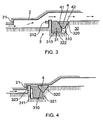
- a first embodiment of a down hole sleeve valve 1 having a valve element 3 provided with a sealing element 4.
- the valve element is shown in an open state of the valve in fig. 1 and a closed state of the valve in fig. 2 .
- the sealing element 4 is in a closed state of the valve arranged butting a valve seat 2, providing a closed fluid path in a closed state of the valve.
- the valve element 3 is in the embodiment shown formed by a sleeve like element.
- the valve seat is in this embodiment also formed by a sleeve element.
- the valve element is moved in an axial direction for movement between an open state and a closed state.
- the valve seat 2 is formed by an inner surface of an outer sleeve element facing in a inward radial direction.
- the valve element 3 comprises a first part 31 and a second part 32.
- the second part 32 is in this embodiment formed like a sleeve element.
- the first element 31 is formed as a ring element and arranged around on the outside of the second part 32, connected to the second part 32 but arranged movable in an axial direct of the second part 31.
- the first part 31 has an inner surface, a gliding surface 313, which is abutting a guiding part 322 of the second part 32.
- the first part is arranged to be movable along the guiding part 322 of the second part 32.
- the second part comprises an abutting surface 320.
- the abutting surface is extending in a mainly radial direction.
- This abutting surface 320 is facing an abutting surface 310 of the first part.
- the sealing element 4 is arranged between these abutting surfaces 320, 310 of the second and first part respectively.
- the abutting surfaces are angled so that they in a cross section as shown in the figures gives a partly V-shape.
- the open end of the V-shape is facing the valve seat 2.
- the sealing element 4 is an annular sealing element.
- An inner surface 43 of the sealing element 4 is abutting the guiding part 322 of the second element 32, and an outer surface 44 of the sealing element will in a closed state of the valve, be abutting the valve seat 2.
- Two opposite surfaces connecting the inner and outer surfaces 43,44 forms a first sealing element surface 41 and a second sealing element surface 42. These surfaces are interacting with the abutting surfaces of the first and second part.
- the first part 31 comprises a pressure surface 311 formed by the surface of the first part 31 facing in an opposite direction of the abutting surface 310.
- the pressure surface will be exposed to the fluid and the pressure in the fluid when the valve is in a closed state.
- a biasing spring 5 In an open state of the valve, as shown in fig. 1 a biasing spring 5 is compressed, and there is a passage through the valve as indicated by the arrows in the figure.
- a closed state the spring 5 is extended and the valve element is moved in an axial direction, thereby moving the sealing element towards the valve seat 2.
- a stopping surface 312 of the first part 31 comes in abutment against a stopping seat 21 formed by the same element forming the valve seat 2, and in the embodiment shown arranged at an end of the valve seat 2. This interaction between the stopping seat 21 and the stopping surface will prevent the first element 31 from moving further in this one direction.
- the spring will then try to press the second part 32 of the valve element towards the first part 31, and since these are arranged movable relative each other, this will press the sealing element 4 in between the two abutting surfaces 310 and 320, and thereby providing a sealing pressure in the sealing element 4.
- the sealing element 4 will also be pressed against the valve seat 2 with this sealing pressure.
- the relative configuration of the first part, the second part, the valve seat, the stopping seat and the stopping surface in addition to the closing force of the valve element, will give a given sealing pressure in the sealing element 4.
- the first part 31 is arranged movable relative the second part 32, and if the pressure of the fluid acting on the pressure surface 311 exceeds the initial sealing pressure, this pressure will further move the first part 31 towards the second part 32 in a closed state of the valve. This movement will give an increase in the sealing pressure in the sealing element 4 , thereby securing a good sealing effect for a range of pressures in the fluid.
- the valve element may also be provided with a stopper element 321, formed as a part of the second part 32 of attached to the second part 32, which stopper element 321 31 interact with a part of the element forming the valve seat 2 and preventing the second part 32from moving further in along the valve seat 2 in a closed state of the valve.
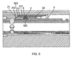
- the first part 31 has the similar features as in the first embodiment, indicated with the same reference numerals, with a pressure surface 311, exposed to the fluid, and an abutting surface 310 abutting the sealing element 4.
- the area of the pressure surface 311 is in this embodiment made larger than the area of the abutting surface 310.
- the protecting part 323 will in an open state of the valve cover at least a part of the pressure surface 311 of the first part 31, from the flow of fluid through the valve.
- the protective part 323 will at least partly prevent the flowing fluid through the valve from hitting the first part 31.
- the protective part 323 is formed as a flange extending in a radial direction and arranged at an end of the guiding part 322 of the second part.
- the abutting surface 320 is arranged at the opposite end of the guiding part 322, seen in a axial direction of the second part 32.
- This protective part 323 will be positioned close to the pressure surface 311 in an open state of the valve, but be moved away from the pressure surface 311 in a closed state of the valve, as the first part 31 is moved relative the second part 32.
- the first part 31 is in this embodiment formed with the stopping surface arranged at an end of at least one rod like part of the first element 31.
- the rod like part extend through the protective part 323.
- the stopping surface 312 at the end of the rod like part will interact with the stopping seat 21 and move the first part relative the second part 32, before the flange shape protective part comes in contact with the stopping seat 21.
- the configuration of the valve element is favorably so that the protective part 323 never abuts the stopping seat 21.
- the configuration of the elements are mainly similar to the second embodiment, with the first and second part 31,32, the stopping surface 312and stopping seat 21and protective part 323, while the protective part 323 is formed as radially extending finger elements arranged in between rod like elements of the first part 31.
- Another features which may be used in all the embodiments are the configurations of the abutting surfaces 310,320 of the first and second part, which form a partly V-shape. The open end of the V-shape is in this embodiment facing away from the valve seat 2.
- the abutting surfaces 310,320 together with an outer surface of the guiding part 322 form a dove tail groove.
- the sealing arrangement may for instance be used with a valve element in the form of a plug.
- the valve seat may be arranged within an outer sleeve formed valve element, the first and or second part of the valve element may comprise several elements together forming the first and or second part.
- the guiding part may be formed by the first element instead of the second element, the pressure surface may alternatively be formed on the second part etc.
Landscapes
- Life Sciences & Earth Sciences (AREA)
- Engineering & Computer Science (AREA)
- Geology (AREA)
- Mining & Mineral Resources (AREA)
- Physics & Mathematics (AREA)
- Environmental & Geological Engineering (AREA)
- Fluid Mechanics (AREA)
- General Life Sciences & Earth Sciences (AREA)
- Geochemistry & Mineralogy (AREA)
- Lift Valve (AREA)
Claims (14)
- Aménagement d'étanchéité pour une soupape, comprenant un élément de soupape (3) prévu avec un élément d'étanchéité (4), agencé pour venir en butée contre un siège de soupape (2) dans un état fermé de la soupape, caractérisé en ce que l'élément de soupape (3) comprend au moins deux parties, une première et une seconde partie (31, 32), chacune comprenant une surface de butée (310, 320), lesquelles surfaces de butée (310, 320) sont aménagées l'une en face de l'autre et pour venir en butée contre des surfaces d'élément d'étanchéité (41, 42) correspondantes de l'élément d'étanchéité (4), et dans lequel au moins une partie (31) de l'élément de soupape (3) est agencé pour être mobile par rapport à une autre partie (32) de l'élément de soupape (3) et la au moins une partie (31) de l'élément de soupape (3) comprend une surface de pression (311) exposée à un fluide environnant dans un état fermé de la soupape fournissant la pression sur l'élément d'étanchéité (4) sensible à la pression du fluide environnant.
- Aménagement d'étanchéité selon la revendication 1, dans lequel le siège de soupape (2) est exposé au fluide s'écoulant à travers la soupape dans un état ouvert de la soupape.
- Aménagement d'étanchéité selon la revendication 1 ou 2, dans lequel les surfaces de butée (310, 320) des deux parties (31) sont des surfaces de butée angulaires aménagées afin de former une forme partiellement en V.
- Aménagement d'étanchéité selon la revendication 3, dans lequel l'extrémité ouverte de la forme en V fait face au siège de soupape (2) à distance.
- Aménagement d'étanchéité selon l'une des revendications 1 à 4, dans lequel la seconde partie (32) comprend une section de protection (323) aménagée en amont de la première partie (31) dans une direction d'écoulement normale à travers la soupape et configurée pour recouvrir au moins une partie de la surface de pression (311) de la première partie (31) de l'écoulement de fluide à travers la soupape dans un état ouvert de la soupape et permettant au fluide d'agir sur la surface de pression (311) dans un état fermé de la soupape.
- Aménagement d'étanchéité selon l'une des revendications précédentes, dans lequel l'élément d'étanchéité est un élément d'étanchéité de forme annulaire.
- Aménagement d'étanchéité selon l'une des revendications précédentes, dans lequel le siège de soupape (2) est formé par un élément de manchon.
- Aménagement d'étanchéité selon l'une des revendications précédentes, dans lequel l'élément de soupape (3) est formé par un élément de manchon.
- Aménagement d'étanchéité selon l'une quelconque des revendications 1 à 7, dans lequel l'élément de soupape (3) est un élément de clapet.
- Aménagement d'étanchéité selon l'une des revendications précédentes, dans lequel l'élément d'étanchéité (4) dans un état fermé de la soupape est comprimé contre le siège de soupape (2) aménagé radialement vers l'extérieur de l'élément d'étanchéité (4).
- Aménagement d'étanchéité selon l'une des revendications 1 à 7, dans lequel l'élément d'étanchéité (4) dans un état fermé de la soupape, est comprimé contre le siège de soupape (2) aménagé radialement à l'intérieur de l'élément d'étanchéité (4).
- Aménagement d'étanchéité selon l'une des revendications précédentes, dans lequel la seconde partie (32) de l'élément de soupape (3) comprend une partie de guidage (322) en butée avec une surface glissante (313) de la première partie (31) de l'élément de soupape (3) permettant le mouvement relatif entre les parties (31, 32).
- Aménagement d'étanchéité selon l'une des revendications précédentes, dans lequel la première partie (31) de l'élément de soupape comprend une surface de butée (312) pour venir en butée contre un siège de butée (21) d'un élément formant le siège de soupape (2), empêchant le mouvement supplémentaire de la première partie (31) dans une direction.
- Aménagement d'étanchéité selon l'une des revendications précédentes, dans lequel la seconde partie (32) comprend une partie de protection (323) aménagée en amont de la première partie (31) dans une direction d'écoulement normale à travers le dispositif de soupape.
Applications Claiming Priority (2)
| Application Number | Priority Date | Filing Date | Title |
|---|---|---|---|
| NO20091531A NO332488B1 (no) | 2009-04-17 | 2009-04-17 | Nedihulls pakningstetning |
| PCT/NO2010/000143 WO2010120191A2 (fr) | 2009-04-17 | 2010-04-16 | Aménagement d'étanchéité pour soupape de fond de trou |
Publications (2)
| Publication Number | Publication Date |
|---|---|
| EP2419599A2 EP2419599A2 (fr) | 2012-02-22 |
| EP2419599B1 true EP2419599B1 (fr) | 2013-06-05 |
Family
ID=42790590
Family Applications (1)
| Application Number | Title | Priority Date | Filing Date |
|---|---|---|---|
| EP10718325.3A Active EP2419599B1 (fr) | 2009-04-17 | 2010-04-16 | Aménagement d'étanchéité pour soupape de fond de trou |
Country Status (5)
| Country | Link |
|---|---|
| US (1) | US8955847B2 (fr) |
| EP (1) | EP2419599B1 (fr) |
| CA (1) | CA2758720C (fr) |
| NO (1) | NO332488B1 (fr) |
| WO (1) | WO2010120191A2 (fr) |
Families Citing this family (1)
| Publication number | Priority date | Publication date | Assignee | Title |
|---|---|---|---|---|
| US8757279B2 (en) | 2012-07-13 | 2014-06-24 | Halliburton Energy Services, Inc. | Pipe in pipe piston thrust system |
Family Cites Families (10)
| Publication number | Priority date | Publication date | Assignee | Title |
|---|---|---|---|---|
| US3381969A (en) * | 1965-02-01 | 1968-05-07 | Dresser Ind | Thermal packer construction |
| DE2637028A1 (de) | 1976-08-17 | 1978-02-23 | Interatom | Dichtung fuer koaxiale, zueinander bewegliche koerper |
| US4953617A (en) | 1989-10-19 | 1990-09-04 | Baker Hughes Incorporated | Apparatus for setting and retrieving a bridge plug from a subterranean well |
| US5997003A (en) * | 1993-04-26 | 1999-12-07 | Cooper Cameron Corporation | Annular sealing assembly and methods of sealing |
| GB9715930D0 (en) * | 1997-07-28 | 1997-10-01 | Smith International | Bypass valve closing means |
| US6772844B2 (en) * | 2001-10-30 | 2004-08-10 | Smith International, Inc. | High pressure sealing apparatus and method |
| IES20020089A2 (en) * | 2002-02-08 | 2003-08-20 | Carsphairn Ltd | An improved pipeline isolation tool |
| US6969070B2 (en) * | 2002-04-12 | 2005-11-29 | Dril-Quip, Inc. | Split carrier annulus seal assembly for wellhead systems |
| US6854522B2 (en) * | 2002-09-23 | 2005-02-15 | Halliburton Energy Services, Inc. | Annular isolators for expandable tubulars in wellbores |
| US7360590B2 (en) * | 2005-04-29 | 2008-04-22 | Baker Hughes Incorporated | Energized thermoplastic sealing element and method of use |
-
2009
- 2009-04-17 NO NO20091531A patent/NO332488B1/no unknown
-
2010
- 2010-04-16 CA CA2758720A patent/CA2758720C/fr active Active
- 2010-04-16 EP EP10718325.3A patent/EP2419599B1/fr active Active
- 2010-04-16 WO PCT/NO2010/000143 patent/WO2010120191A2/fr not_active Ceased
- 2010-04-16 US US13/262,919 patent/US8955847B2/en active Active
Also Published As
| Publication number | Publication date |
|---|---|
| NO20091531L (no) | 2010-10-18 |
| CA2758720A1 (fr) | 2010-10-21 |
| NO332488B1 (no) | 2012-10-01 |
| US20120112115A1 (en) | 2012-05-10 |
| WO2010120191A3 (fr) | 2010-12-16 |
| WO2010120191A2 (fr) | 2010-10-21 |
| CA2758720C (fr) | 2017-05-16 |
| EP2419599A2 (fr) | 2012-02-22 |
| US8955847B2 (en) | 2015-02-17 |
Similar Documents
| Publication | Publication Date | Title |
|---|---|---|
| EP3036465B1 (fr) | Agencement d'étanchéité de soupape | |
| TWI596289B (zh) | Valve device and pipe fitting provided with a valve device | |
| EP2370665B1 (fr) | Dispositif de commande d'ecoulement | |
| EP3591272B1 (fr) | Clapet anti-retour | |
| CN101617163A (zh) | 带关闭阀的连接构件 | |
| CA2606139A1 (fr) | Dispositif de garniture d'etancheite annulaire pouvant se deplacer sur un element tubulaire | |
| RU2017129797A (ru) | Сопловой обратный клапан | |
| TR201904772T4 (tr) | Eğimli boru ile beslenen arka hazneli sıvı iletimi bağlantısı. | |
| KR101402265B1 (ko) | 저력형 고착방지 스로틀 밸브 | |
| AU2012208960B2 (en) | Water hammer arrester | |
| FI106929B (sv) | Spruthuvud | |
| CA2758720C (fr) | Amenagement d'etancheite pour soupape de fond de trou | |
| WO2016100029A1 (fr) | Soupape de pointe | |
| US9267357B2 (en) | Multi-component diffuser assembly | |
| EP2859258B1 (fr) | Joint d'étanchéité à volet incurvé comportant une surface intermédiaire épaulée | |
| GB2481844A (en) | Fluid control valve | |
| EP3341634B1 (fr) | Joints d'étanchéité métal-métal à auto-centrage pour une utilisation avec des vannes | |
| KR950001152A (ko) | 글러브 밸브 | |
| EP3092348B1 (fr) | Valve de limitation et ensemble à valve | |
| US20150027683A1 (en) | Heat exchange device | |
| EP3482109B1 (fr) | Vanne à manchon | |
| CA2897493A1 (fr) | Dispositif de soupape | |
| EP3601866B1 (fr) | Ensemble vanne destiné à être utilisé dans un tuyau de fluide | |
| EP3092429B1 (fr) | Clapet et ensemble | |
| EP2878891A1 (fr) | Un électro-aimant avec ressort absorbant les chocs |
Legal Events
| Date | Code | Title | Description |
|---|---|---|---|
| PUAI | Public reference made under article 153(3) epc to a published international application that has entered the european phase |
Free format text: ORIGINAL CODE: 0009012 |
|
| 17P | Request for examination filed |
Effective date: 20111117 |
|
| AK | Designated contracting states |
Kind code of ref document: A2 Designated state(s): AT BE BG CH CY CZ DE DK EE ES FI FR GB GR HR HU IE IS IT LI LT LU LV MC MK MT NL NO PL PT RO SE SI SK SM TR |
|
| DAX | Request for extension of the european patent (deleted) | ||
| REG | Reference to a national code |
Ref country code: DE Ref legal event code: R079 Ref document number: 602010007626 Country of ref document: DE Free format text: PREVIOUS MAIN CLASS: E21B0034120000 Ipc: E21B0034060000 |
|
| RIC1 | Information provided on ipc code assigned before grant |
Ipc: E21B 34/06 20060101AFI20120928BHEP |
|
| GRAP | Despatch of communication of intention to grant a patent |
Free format text: ORIGINAL CODE: EPIDOSNIGR1 |
|
| GRAP | Despatch of communication of intention to grant a patent |
Free format text: ORIGINAL CODE: EPIDOSNIGR1 |
|
| GRAS | Grant fee paid |
Free format text: ORIGINAL CODE: EPIDOSNIGR3 |
|
| GRAA | (expected) grant |
Free format text: ORIGINAL CODE: 0009210 |
|
| AK | Designated contracting states |
Kind code of ref document: B1 Designated state(s): AT BE BG CH CY CZ DE DK EE ES FI FR GB GR HR HU IE IS IT LI LT LU LV MC MK MT NL NO PL PT RO SE SI SK SM TR |
|
| REG | Reference to a national code |
Ref country code: GB Ref legal event code: FG4D |
|
| REG | Reference to a national code |
Ref country code: CH Ref legal event code: EP |
|
| REG | Reference to a national code |
Ref country code: AT Ref legal event code: REF Ref document number: 615783 Country of ref document: AT Kind code of ref document: T Effective date: 20130615 |
|
| REG | Reference to a national code |
Ref country code: IE Ref legal event code: FG4D |
|
| REG | Reference to a national code |
Ref country code: DE Ref legal event code: R096 Ref document number: 602010007626 Country of ref document: DE Effective date: 20130801 |
|
| REG | Reference to a national code |
Ref country code: AT Ref legal event code: MK05 Ref document number: 615783 Country of ref document: AT Kind code of ref document: T Effective date: 20130605 |
|
| PG25 | Lapsed in a contracting state [announced via postgrant information from national office to epo] |
Ref country code: AT Free format text: LAPSE BECAUSE OF FAILURE TO SUBMIT A TRANSLATION OF THE DESCRIPTION OR TO PAY THE FEE WITHIN THE PRESCRIBED TIME-LIMIT Effective date: 20130605 Ref country code: SI Free format text: LAPSE BECAUSE OF FAILURE TO SUBMIT A TRANSLATION OF THE DESCRIPTION OR TO PAY THE FEE WITHIN THE PRESCRIBED TIME-LIMIT Effective date: 20130605 Ref country code: SE Free format text: LAPSE BECAUSE OF FAILURE TO SUBMIT A TRANSLATION OF THE DESCRIPTION OR TO PAY THE FEE WITHIN THE PRESCRIBED TIME-LIMIT Effective date: 20130605 Ref country code: ES Free format text: LAPSE BECAUSE OF FAILURE TO SUBMIT A TRANSLATION OF THE DESCRIPTION OR TO PAY THE FEE WITHIN THE PRESCRIBED TIME-LIMIT Effective date: 20130916 Ref country code: FI Free format text: LAPSE BECAUSE OF FAILURE TO SUBMIT A TRANSLATION OF THE DESCRIPTION OR TO PAY THE FEE WITHIN THE PRESCRIBED TIME-LIMIT Effective date: 20130605 Ref country code: NO Free format text: LAPSE BECAUSE OF FAILURE TO SUBMIT A TRANSLATION OF THE DESCRIPTION OR TO PAY THE FEE WITHIN THE PRESCRIBED TIME-LIMIT Effective date: 20130905 Ref country code: LT Free format text: LAPSE BECAUSE OF FAILURE TO SUBMIT A TRANSLATION OF THE DESCRIPTION OR TO PAY THE FEE WITHIN THE PRESCRIBED TIME-LIMIT Effective date: 20130605 Ref country code: GR Free format text: LAPSE BECAUSE OF FAILURE TO SUBMIT A TRANSLATION OF THE DESCRIPTION OR TO PAY THE FEE WITHIN THE PRESCRIBED TIME-LIMIT Effective date: 20130906 |
|
| REG | Reference to a national code |
Ref country code: NL Ref legal event code: VDEP Effective date: 20130605 |
|
| REG | Reference to a national code |
Ref country code: LT Ref legal event code: MG4D |
|
| PG25 | Lapsed in a contracting state [announced via postgrant information from national office to epo] |
Ref country code: BG Free format text: LAPSE BECAUSE OF FAILURE TO SUBMIT A TRANSLATION OF THE DESCRIPTION OR TO PAY THE FEE WITHIN THE PRESCRIBED TIME-LIMIT Effective date: 20130905 Ref country code: HR Free format text: LAPSE BECAUSE OF FAILURE TO SUBMIT A TRANSLATION OF THE DESCRIPTION OR TO PAY THE FEE WITHIN THE PRESCRIBED TIME-LIMIT Effective date: 20130605 |
|
| PG25 | Lapsed in a contracting state [announced via postgrant information from national office to epo] |
Ref country code: LV Free format text: LAPSE BECAUSE OF FAILURE TO SUBMIT A TRANSLATION OF THE DESCRIPTION OR TO PAY THE FEE WITHIN THE PRESCRIBED TIME-LIMIT Effective date: 20130605 |
|
| PG25 | Lapsed in a contracting state [announced via postgrant information from national office to epo] |
Ref country code: IS Free format text: LAPSE BECAUSE OF FAILURE TO SUBMIT A TRANSLATION OF THE DESCRIPTION OR TO PAY THE FEE WITHIN THE PRESCRIBED TIME-LIMIT Effective date: 20131005 Ref country code: CZ Free format text: LAPSE BECAUSE OF FAILURE TO SUBMIT A TRANSLATION OF THE DESCRIPTION OR TO PAY THE FEE WITHIN THE PRESCRIBED TIME-LIMIT Effective date: 20130605 Ref country code: PT Free format text: LAPSE BECAUSE OF FAILURE TO SUBMIT A TRANSLATION OF THE DESCRIPTION OR TO PAY THE FEE WITHIN THE PRESCRIBED TIME-LIMIT Effective date: 20131007 Ref country code: EE Free format text: LAPSE BECAUSE OF FAILURE TO SUBMIT A TRANSLATION OF THE DESCRIPTION OR TO PAY THE FEE WITHIN THE PRESCRIBED TIME-LIMIT Effective date: 20130605 Ref country code: BE Free format text: LAPSE BECAUSE OF FAILURE TO SUBMIT A TRANSLATION OF THE DESCRIPTION OR TO PAY THE FEE WITHIN THE PRESCRIBED TIME-LIMIT Effective date: 20130605 Ref country code: SK Free format text: LAPSE BECAUSE OF FAILURE TO SUBMIT A TRANSLATION OF THE DESCRIPTION OR TO PAY THE FEE WITHIN THE PRESCRIBED TIME-LIMIT Effective date: 20130605 |
|
| PG25 | Lapsed in a contracting state [announced via postgrant information from national office to epo] |
Ref country code: RO Free format text: LAPSE BECAUSE OF FAILURE TO SUBMIT A TRANSLATION OF THE DESCRIPTION OR TO PAY THE FEE WITHIN THE PRESCRIBED TIME-LIMIT Effective date: 20130605 Ref country code: PL Free format text: LAPSE BECAUSE OF FAILURE TO SUBMIT A TRANSLATION OF THE DESCRIPTION OR TO PAY THE FEE WITHIN THE PRESCRIBED TIME-LIMIT Effective date: 20130605 Ref country code: NL Free format text: LAPSE BECAUSE OF FAILURE TO SUBMIT A TRANSLATION OF THE DESCRIPTION OR TO PAY THE FEE WITHIN THE PRESCRIBED TIME-LIMIT Effective date: 20130605 |
|
| PLBE | No opposition filed within time limit |
Free format text: ORIGINAL CODE: 0009261 |
|
| STAA | Information on the status of an ep patent application or granted ep patent |
Free format text: STATUS: NO OPPOSITION FILED WITHIN TIME LIMIT |
|
| PG25 | Lapsed in a contracting state [announced via postgrant information from national office to epo] |
Ref country code: DK Free format text: LAPSE BECAUSE OF FAILURE TO SUBMIT A TRANSLATION OF THE DESCRIPTION OR TO PAY THE FEE WITHIN THE PRESCRIBED TIME-LIMIT Effective date: 20130605 |
|
| 26N | No opposition filed |
Effective date: 20140306 |
|
| PG25 | Lapsed in a contracting state [announced via postgrant information from national office to epo] |
Ref country code: IT Free format text: LAPSE BECAUSE OF FAILURE TO SUBMIT A TRANSLATION OF THE DESCRIPTION OR TO PAY THE FEE WITHIN THE PRESCRIBED TIME-LIMIT Effective date: 20130605 |
|
| REG | Reference to a national code |
Ref country code: DE Ref legal event code: R097 Ref document number: 602010007626 Country of ref document: DE Effective date: 20140306 |
|
| PG25 | Lapsed in a contracting state [announced via postgrant information from national office to epo] |
Ref country code: LU Free format text: LAPSE BECAUSE OF FAILURE TO SUBMIT A TRANSLATION OF THE DESCRIPTION OR TO PAY THE FEE WITHIN THE PRESCRIBED TIME-LIMIT Effective date: 20140416 Ref country code: MC Free format text: LAPSE BECAUSE OF FAILURE TO SUBMIT A TRANSLATION OF THE DESCRIPTION OR TO PAY THE FEE WITHIN THE PRESCRIBED TIME-LIMIT Effective date: 20130605 |
|
| REG | Reference to a national code |
Ref country code: CH Ref legal event code: PL |
|
| PG25 | Lapsed in a contracting state [announced via postgrant information from national office to epo] |
Ref country code: LI Free format text: LAPSE BECAUSE OF NON-PAYMENT OF DUE FEES Effective date: 20140430 Ref country code: CH Free format text: LAPSE BECAUSE OF NON-PAYMENT OF DUE FEES Effective date: 20140430 |
|
| PG25 | Lapsed in a contracting state [announced via postgrant information from national office to epo] |
Ref country code: MT Free format text: LAPSE BECAUSE OF FAILURE TO SUBMIT A TRANSLATION OF THE DESCRIPTION OR TO PAY THE FEE WITHIN THE PRESCRIBED TIME-LIMIT Effective date: 20130605 |
|
| REG | Reference to a national code |
Ref country code: FR Ref legal event code: PLFP Year of fee payment: 7 |
|
| PG25 | Lapsed in a contracting state [announced via postgrant information from national office to epo] |
Ref country code: SM Free format text: LAPSE BECAUSE OF FAILURE TO SUBMIT A TRANSLATION OF THE DESCRIPTION OR TO PAY THE FEE WITHIN THE PRESCRIBED TIME-LIMIT Effective date: 20130605 |
|
| PG25 | Lapsed in a contracting state [announced via postgrant information from national office to epo] |
Ref country code: CY Free format text: LAPSE BECAUSE OF FAILURE TO SUBMIT A TRANSLATION OF THE DESCRIPTION OR TO PAY THE FEE WITHIN THE PRESCRIBED TIME-LIMIT Effective date: 20130605 |
|
| PG25 | Lapsed in a contracting state [announced via postgrant information from national office to epo] |
Ref country code: HU Free format text: LAPSE BECAUSE OF FAILURE TO SUBMIT A TRANSLATION OF THE DESCRIPTION OR TO PAY THE FEE WITHIN THE PRESCRIBED TIME-LIMIT; INVALID AB INITIO Effective date: 20100416 Ref country code: TR Free format text: LAPSE BECAUSE OF FAILURE TO SUBMIT A TRANSLATION OF THE DESCRIPTION OR TO PAY THE FEE WITHIN THE PRESCRIBED TIME-LIMIT Effective date: 20130605 |
|
| REG | Reference to a national code |
Ref country code: FR Ref legal event code: PLFP Year of fee payment: 8 |
|
| REG | Reference to a national code |
Ref country code: FR Ref legal event code: PLFP Year of fee payment: 9 |
|
| PG25 | Lapsed in a contracting state [announced via postgrant information from national office to epo] |
Ref country code: MK Free format text: LAPSE BECAUSE OF FAILURE TO SUBMIT A TRANSLATION OF THE DESCRIPTION OR TO PAY THE FEE WITHIN THE PRESCRIBED TIME-LIMIT Effective date: 20130605 |
|
| PGFP | Annual fee paid to national office [announced via postgrant information from national office to epo] |
Ref country code: RO Payment date: 20190606 Year of fee payment: 11 |
|
| PG25 | Lapsed in a contracting state [announced via postgrant information from national office to epo] |
Ref country code: IE Free format text: LAPSE BECAUSE OF NON-PAYMENT OF DUE FEES Effective date: 20200416 |
|
| P01 | Opt-out of the competence of the unified patent court (upc) registered |
Effective date: 20230512 |
|
| PGFP | Annual fee paid to national office [announced via postgrant information from national office to epo] |
Ref country code: DE Payment date: 20250430 Year of fee payment: 16 |
|
| PGFP | Annual fee paid to national office [announced via postgrant information from national office to epo] |
Ref country code: GB Payment date: 20250429 Year of fee payment: 16 |
|
| PGFP | Annual fee paid to national office [announced via postgrant information from national office to epo] |
Ref country code: FR Payment date: 20250430 Year of fee payment: 16 |