EP2420177B1 - Lave-vaisselle, notamment lave-vaisselle ménager - Google Patents
Lave-vaisselle, notamment lave-vaisselle ménager Download PDFInfo
- Publication number
- EP2420177B1 EP2420177B1 EP11176226.6A EP11176226A EP2420177B1 EP 2420177 B1 EP2420177 B1 EP 2420177B1 EP 11176226 A EP11176226 A EP 11176226A EP 2420177 B1 EP2420177 B1 EP 2420177B1
- Authority
- EP
- European Patent Office
- Prior art keywords
- holding part
- supporting frame
- latching
- dishwasher
- dishwasher according
- Prior art date
- Legal status (The legal status is an assumption and is not a legal conclusion. Google has not performed a legal analysis and makes no representation as to the accuracy of the status listed.)
- Active
Links
Images


Classifications
-
- A—HUMAN NECESSITIES
- A47—FURNITURE; DOMESTIC ARTICLES OR APPLIANCES; COFFEE MILLS; SPICE MILLS; SUCTION CLEANERS IN GENERAL
- A47L—DOMESTIC WASHING OR CLEANING; SUCTION CLEANERS IN GENERAL
- A47L15/00—Washing or rinsing machines for crockery or tableware
- A47L15/42—Details
- A47L15/4251—Details of the casing
- A47L15/4272—Supporting arrangements for the tub
Definitions
- the invention relates to a dishwasher, in particular a domestic dishwasher, according to the preamble of claim 1.
- the support structure carries in particular the washing and other equipment units.
- a support structure of a dishwasher may have a mounting base as a support floor structure which has a hinge plate at its two front corner areas.
- the term assembly floor can, in particular also with regard to the invention, preferably also be understood to mean a floor assembly or base support assembly to which the washing container of the dishwasher is placed.
- various functional components of the dishwasher such as a lye pump, circulating pump, control device, a power module, etc .. be housed.
- the appliance door can be pivoted.
- the hinge plates can carry, support and / or fix the intermediate rinsing container arranged therebetween.
- a carrier frame part attached to the washing container in the region of its front-side feed opening can be fixed or fastened to it.
- the washing container can also be supported on the back of the appliance directly on the mounting floor.
- the rinsing container can be made in two parts from an upper, in the cross-sectional profile viewed from the front U-shaped sheet metal hood, which forms the side, rear and top wall of the washing compartment, and a plastic bottom pan, which can be supported between the two hinge plates of the mounting base.
- the limited by the metal cover, front loading opening of the washing can be partially or completely wrapped by a support frame part along a front edge region, which is in particular made of plastic material. If necessary, this type of construction can also be used in a dishwashing machine according to the invention.
- a top-side table top of the dishwasher or kitchen worktop or a ceiling wall of a niche can be attacked.
- the table top or worktop is usually connected directly to the support frame part, so that the lifting forces are forwarded to the connection points between the support frame part and the hinge plates.
- both the lifting forces and in the opposite direction to the weight forces of the mounting floor act on these connection points. Accordingly, high demands are to be made on strength at these connection points.
- the object of the invention is to provide a dishwasher with a stable supporting structure, with which a simple assembly is made possible.
- the object is solved by the features of claim 1. Characterized in that in the dishwasher according to the invention, in particular domestic dishwasher, with a washing container, in which a supporting frame part is mounted in the region of its front loading opening, wherein the support frame part is attached to at least one bottom support member, the support frame part of the washing through at least one latching connection with the bottom side support member is connected, a structurally simpler and easier assembly of the dishwasher according to the invention is provided.
- the dishwashing machine preferably has a supporting frame part which moves around a front loading opening of a washing container.
- This is in particular at least one base-side support member, preferably a bottom-side support strut, preferably a hinge plate of a mounting base attached.
- the support frame part is connected via at least one latching connection with the base-side support part, in particular the support strut.
- the support frame part or the support frame which may be formed in particular one or more parts, can therefore be set in a simple manner during assembly on the support member, in particular the support strut of the mounting base and simultaneously locked so that additional assembly steps, such as for screwing the support strut on Support frame, can be omitted.
- the latching connection according to the invention advantageously allows a mounting-friendly plug-in movement of the support frame to the bottom-side support member during assembly of the dishwasher constructed according to the invention.
- the dishwasher in particular domestic dishwasher, with a rinsing container to which a support frame part is attached in the region of its front loading opening, wherein the rinsing container sits on a support base structure having a bottom-side support member, and wherein the support frame part on the is mounted on the bottom side support member, the support frame part of the washing and the bottom support member are fixed only by means of one or more snap-in connections in their assembly direction, in particular tool-free, angiokoppelbar and in their final assembly position in the direction of separation against loosening.
- This facilitates the assembly of the dishwasher and at the same time reliably ensures the cohesion of their components flushing container and supporting floor structure.
- latching elements cooperating with each other may be provided both on the base-side support part, in particular the support strut, and on the support frame.
- the locking elements can be integrated materially and integrally with respect to a component reduction in each case on the support member, in particular the support strut, and on the support frame.
- the latching connection produced in this way can preferably be released again by applying a corresponding tool.
- connection point between the support frame part and the base-side support parts, in particular the hinge plates is especially heavily loaded when the dishwasher is engaged in the upper area and then lifted. In this case, the entire weight of the fitted assembly components with device components acts on this connection point.
- the respective latching connection assigned in particular a height stop which secures the support frame against loosening of the respective bottom-side support member, in particular of the respective support strut in the device vertical direction.
- the height stop can be in a double function at the same time also a locking element of the locking connection. If the respective support strut is made of a sheet metal material, the latching element can be punched from the sheet material and bent as a sheet metal tab from the support strut. The sheet metal tab acting as a height stop can be underrun in the device pulling direction by the second latching element of the latching connection. With a vertical lifting of the dishwasher thus reliable inadvertent release of the support frame is prevented by the support strut.
- the second locking element may be executed in contrast to the above-mentioned sheet metal tab as an elastically resilient locking tab. The elastically yielding locking tab can escape when assembling the support frame with the support strut to build up a restoring force and overcome the rigid sheet metal tab in positionally correct positioning and reach behind this.
- the support frame may expediently have a positioning shaft at its, the support strut end facing.
- the support strut can protrude into the positioning shaft, while the positioning shaft can ensure a correct position positioning during the joining process.
- the latching connection between a side wall of the positioning shaft and the support strut is executed.
- the support frame-side locking tab can be easily accessible in the, arranged in the device width direction outer side wall of the positioning shaft.
- a laterally accessible tool window can be provided in this outer side wall of the positioning shaft.
- the locking tab can be arranged directly on the lower edge of the window of this tool window.
- the geometry of the positioning shaft is preferably designed such that it follows the shaping of the support strut contour of the respective support strut to be inserted therein.
- the positioning shaft may have a depth stop, which allows a substantially backlash-free contact between the support frame and the support strut in the depth direction of the washing container.
- the positioning shaft can have a side stop, which prevents movement play between the support frame and the support strut in the device width direction.
- the hinge plate or the support strut is formed from a sheet material having a sufficiently large sheet thickness in order to provide a required component stability.
- the sheet metal tab bent out of the respective support strut is in particular designed to be substantially rigid, while the respectively cooperating plastic bottle of the support frame part is elastically yielding in comparison thereto. To release the locking connection, therefore, the tool is preferably attached to the respective plastic tab.
- the gap width of the positioning shaft is dimensioned small, that is approximately equal to the material thickness of the support strut.
- the support strut can have as an insertion aid a laterally projecting expression.
- the molded in the support strut expression is used to expand the positioning shaft during assembly.
- the sheet metal tab can be molded directly in the laterally, in particular in the device width direction protruding expression.
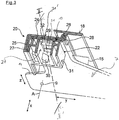
- Fig. 1 is fragmentary and limited to a front, lower corner region of the dishwasher, a supporting floor structure viewed from the outside, which carries the washing compartment 1 of the dishwasher. Thus, the washing container 1 sits on this support structure.
- the Indian Fig. 1 In contrast, opposite front corner region of the dishwasher, which is not illustrated, is designed with a supporting floor structure which is designed as a mirror image of it.
- the support structure of the washing container 1 has a mounting base 3 with laterally raised, circumferential side walls.
- device components such as a drain pump and / or a circulating pump, are arranged in a conventional manner.
- the mounting floor can also be in the form of a floor assembly or a base support structure be educated.
- the mounting base 3 is made for example of plastic and has according to the Fig. 1 an assembly shaft 5, in which a hinge support, in particular a hinge plate 7 is used as an upwardly projecting support strut.
- the hinge plate 7 is formed from a sheet metal blank and designed as a rigid, supporting member with a correspondingly large plate thickness.
- the hinge plate 7 On the hinge plate 7 is hinged on the one hand in a bearing opening 9, an unillustrated hinge lever for a door, making it a in the Fig. 1 shown pivot axis A can pivot.
- the two front hinge plates 7 here carry an interposed plastic base pan 11 of the washing container 1 Fig. 1 the bottom pan 11 has front angled side edges 13, which follow approximately the respective front edge profile of the two laterally mounted on the mounting base hinge plates 7 and are supported on the front edge 14 of the hinge plates 7.
- the washing compartment 1 has a box-shaped, downwardly open sheet metal hood, which forms both the side walls, the rear wall and the top wall of the washing compartment 1.
- the sheet metal hood is therefore U-shaped viewed from the front, ie it has a front loading opening 17, which is bounded or bounded by laterally arranged in the width of the mounting base 3 transverse distance sidewall end faces and a roof wall front side and bottom open.
- a front-side charging opening 17 of the washing compartment 1 is characterized by a in the Fig. 1 limited only in dashed line indicated plastic frame 18.
- the plastic frame 18 follows in particular the U-shaped contour of the front end face of the washing container 1.
- the U-shaped plastic frame 18 is supported at its two, spaced apart in the width distance of the feed opening, lower leg ends both on the bottom pan 11 and on the hinge plate 7.
- the support frame 18 is connected via a latching connection 20 fixed to the hinge plate 7.
- the respective hinge plate 7 thus forms a support member for the U-shaped support frame 18 which is fixedly attached in the front region of the U-shaped Spül matterserhaube.
- the locking connection 20 is in the Fig. 1 because of Clarity only a sheet metal tab 21 of the hinge plate 7 shown in accordance with the Fig. 2 and 3 with a plastic bottle 29 on the U-shaped plastic support frame 18 cooperates (see Figures 2-4 ).
- the locking connection 20 between the support frame 18 and the hinge plate 7 secures the support frame 18 of the washing compartment 1 against loosening of the hinge plate 7 in the peeling direction z upwards and is in the following Fig. 2 . 3 and 4 shown in more detail.
- the respective hinge plate 7 has a preferably vertically upwardly projecting support leg 19 which is inserted into a positioning shaft 22 at the lower end of the plastic frame 18.
- the support leg 19 at its upper portion in the device width direction x bent outward sheet metal tab 21. It stands out in the height and width direction z, x extending positional plane of the respective hinge plate 7 in the normal direction x to this.
- Her front end thus has in the width direction x considered a distance from the outer side surface of the hinge plate.
- the latching tab 21 is punched out of the sheet material of the hinge carrier 7.
- the latching tab 21 is located in an outwardly bulging expression 23 of the support leg 19.
- the latching tab 21 is preferably made by a material cut in the form of a plate-shaped hinge support member 7. Below the locking tab 21 in particular a window opening 36 is provided in the support member 7.
- the support leg 13 of the respective hinge plate 7 is inserted into a respective positioning shaft 22 in the associated side limb of the support frame 18.
- the respective positioning shaft 22 is executed in a vertical section in the plane defined by the width direction x and height direction z plane in an approximately U-shaped downwardly open.
- the inner contour course of the positioning shaft 22 is adapted to the contour of the support leg 19, in particular from the Fig. 3 is apparent.
- the support leg 19 in the plane spanned by the width and height direction x, z layer edge margins 25, 26 which are bent in the device width direction x in opposite directions and with respect to its extension plane in the depth and height direction y, z are bent at right angles.
- these two edge webs 25, 26 of the support leg 13 are substantially free of play in corresponding groove portions 27, 28 of the Positionierschachtes 22 used as depth stops the support legs 19th Position in depth direction y.
- the base portion 24 of the support leg 19 which connects the two edge webs 25, 26 and extends in the y, z position plane is likewise inserted without clearance between the outer side wall 31 of the positioning shaft 22 and its inner side wall 31 ', as a result of which the support leg 19 is also in the device width direction x is positioned correctly.
- the relies in the Fig. 1 shown top edge 33 of the respective support leg 19 on the bottom 34 of the respective associated U-shaped positioning shaft 22 from.
- the latching connection produced between the latching tabs 21, 29 is largely free of weight forces, which according to the invention can be absorbed mainly by the upper edge 33 of the support leg 19 and optionally in addition from the bottom pan 11.
- the bent-out sheet metal tab 29 of the hinge plate 7 is engaged by the corresponding plastic tab 29 of the support frame 18, as shown in the Fig. 2 . 3 and 4 is apparent.
- the plastic tab 29 is bent for this purpose in the device width direction x inward and in abutting connection with the bent-out sheet metal tab 21st
- an access window 37 is formed accessible from the outside in order to allow tool access for releasing the latching connection 20.
- the window 37 is in accordance with the Fig. 3 formed inwardly lifted plastic tab 29.
- the plastic tab 29 is to be bent outwards by means of a tool in the device width direction x.
- the edge web 25 of the respective support leg 19 can therefore initially strike against the run-on slope 35 in the groove section of the respectively assigned positioning shaft 22 during assembly.
- the edge web 25 can then be guided in a positionally reliable manner into the groove section 27.
- the inwardly bent plastic bottle 29 is displaced elastically outwards during the course of the joining in order to overcome the rigid, outwardly bent sheet metal tab 21.
- the plastic tab 29 jumps back in the width direction x inwards to its rest position, in which the rigid sheet metal tab 21 is under attack.
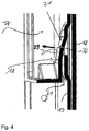
- FIG. 4 finally shows a vertical section through the latching connection of FIG.
- first latching element of the respective latching connection 20 is a, in particular substantially rigid, latching tab 21 is provided on the leg 19 of the respective hinge plate 7.
- the locking tab 21 is made by a material cut from the sheet material of the hinge plate 7.
- Below the locking tab 21 in particular a window opening 36 in the hinge plate 7 is provided (see FIG. 1 ).
- This first locking element 21 is engaged in the device vertical direction z of the second locking element 29 on the support frame part 18 when the two side legs of the support frame part 18 have been placed on the support legs 19 of the two hinge plates 7 and placed in their final assembly position.
- the locking element 21 of the support member 7 is in a window opening 37 in the outside wall 31 of the profiled support frame part 7 from.
- the second latching element 29 is in the latching position of support frame part 18 and support member 7 opposite to the first latching element 21 and engages under this. It is directed obliquely upwards, while the first locking element is directed obliquely down to the free end of the second locking element 29 to.
- a hooking of the two locking elements against each other is ensured when 18 forces in the height direction upwards z are effective on the support frame part.
- the front end of the cross-engaging second locking element 29th on the support frame part 18 is then supported on the downward facing end of the fixed first latching element 21 of the support leg 19.
- the support frame part 18 of the washing container 1 is connected via at least one locking connection 20 with the bottom-side support member 7 in a reliable manner.
- the support frame part 18 of the rinsing container 1 and the base-side support part 7 are fixed in their assembly direction, preferably tool-free, and can be coupled together in their final assembly position in the direction of separation against loosening only by means of one or more snap-in connections 20.
- the rinsing container such as 1 comprises, in particular, a front view of a U-shaped hood part, along the front-side edge region of the support frame part such as 18 is mounted.
- the bottom-side support member such as 7 is preferably formed as a support strut.
- the support strut is in particular formed by a hinge plate, which is attached to a supporting floor structure, in particular a mounting floor, below the washing compartment.
- the cooperating latching elements such as 21, 29 of the respective latching connection 20 are expediently of the same material and / or integrally on the bottom support member, in particular on a support strut, preferably hinge plate of the washing container supporting support structure, and / or integrated on the support frame part.
- the latching connection can be assigned in an advantageous manner a height stop, which secures the support frame part against loosening of the bottom-side support member in the device vertical direction.
- the height stop can be designed, in particular, as a first latching element, such as 21, on the base-side holding part, wherein the first latching element is, in particular, a rigid latching strap of the holding part.
- the first locking tab can be made in particular by a material cut in the support member. Below this locking tab, in particular, a window opening such as 36 may be provided in the support member.
- the height stop such as 21 on the support member is under attack in the device vertical direction z of a second locking element such as 29 on the support frame part such as 18, wherein the second locking element is in particular an elastically resilient locking tab of the support frame part.
- the first locking element such as 21 of the Holder part is in the final assembly position of support frame part and support member in a window opening such as 37 in the outside wall such as 31 of the support frame part from.
- the second locking element such as 29 is the first locking element such as 21 in the opposite direction and thereby engages this.
- the support frame part at its two holding parts facing ends each have a positioning shaft such as 22, in which projects the respective leg end of the support member.
- the locking connection such as 20 is expediently carried out between an outer side wall such as 31 of the positioning shaft such as 22 and the support member.
- the respective positioning shaft of the support frame part expediently has at least one depth stop and / or one side stop such as 27, 28, which position the holding part in the device width and / or depth direction x, y.
- the ground such as 34 of the positioning shaft such as 22 of the respective leg of the U-shaped support frame part is supported in particular on the upper side of the respective support member.
- the latching element in particular the latching tab such as 29, of the support frame part in a, in the device width direction x outer side wall such as 31 of the positioning shaft 22 is arranged.
- the outer side wall such as 31 of the positioning shaft such as 22 has a laterally accessible from the outside window such as 37, which allows a tool access to the locking connection.
- the support frame part of a plastic material and the support member are formed of a sheet metal material.
- the gap width of the positioning shaft of the support frame part corresponds approximately to a material thickness of the support part.
Landscapes
- Washing And Drying Of Tableware (AREA)
Claims (21)
- Lave-vaisselle, notamment lave-vaisselle ménager, comportant une cuve de lavage (1), sur laquelle un élément de cadre porteur (18) est monté dans la zone de son ouverture de chargement (17) frontale, dans lequel l'élément de cadre porteur (18) est fixé à au moins un élément de support (7) du côté sol,
caractérisé en ce que l'élément de cadre porteur (18) de la cuve de lavage est relié à l'élément de support (7) du côté sol par l'intermédiaire d'au moins une liaison par encliquetage (20). - Lave-vaisselle selon la revendication 1, caractérisé en ce que la cuve de lavage (1) comprend une partie de capot en forme de U selon une vue de face, le long de la zone de bordure frontale de laquelle l'élément de cadre porteur (18) est monté.
- Lave-vaisselle selon l'une des revendications 1 ou 2, caractérisé en ce que l'élément de support du côté sol (7) est configuré sous forme d'un montant de support.
- Lave-vaisselle selon la revendication 3, caractérisé en ce que le montant de support est formé par un bloc charnière, qui est monté sur une structure portante (3), notamment un sol de montage, sous la cuve de lavage (1).
- Lave-vaisselle selon l'une des revendications précédentes, caractérisé en ce que la une ou plusieurs liaisons par encliquetage (20) est (sont) configurée(s) de manière à ce que l'élément de cadre porteur (18) et l'élément de support côté sol (7) peuvent être accouplés l'un à l'autre au moyen de la une ou plusieurs liaisons par encliquetage (20) dans leur direction d'assemblage, notamment sans outil, et sont assurés contre un desserrage, dans leur position de montage finale, dans une direction de traction l'un par rapport à l'autre.
- Lave-vaisselle selon l'une des revendications précédentes, caractérisé en ce que les éléments d'encliquetage (21, 29) coopérants de la liaison par encliquetage (20) sont intégrés en un même matériau et/ou d'un seul tenant sur l'élément de support côté sol (7), notamment sur un montant de support, de préférence un bloc charnière de la structure portante (3) soutenant la cuve de lavage (1) et/ou sur l'élément de cadre porteur (18).
- Lave-vaisselle selon l'une des revendications précédentes, caractérisé en ce qu'une butée de hauteur (21) est affectée à la liaison par encliquetage (20), laquelle butée de hauteur assure l'élément de cadre porteur (18) contre un détachement de l'élément de support côté sol (7) dans la direction verticale de l'appareil (z).
- Lave-vaisselle selon la revendication 7, caractérisé en ce que la butée en hauteur (21) est configurée sous forme d'un premier élément d'encliquetage sur l'élément de support côté sol (7), le premier élément d'encliquetage (21) étant notamment une patte d'accrochage rigide de l'élément de support (7).
- Lave-vaisselle selon la revendication 8, caractérisé en ce que la patte d'accrochage (21) est fabriquée par une découpe de matière dans l'élément de support (7) et en ce que notamment un ajour de fenêtre (36) est agencé dans l'élément de support (7) en dessous de la patte d'accrochage (21).
- Lave-vaisselle selon la revendication 7 et 9, caractérisé en ce que la butée de hauteur (21) est saisie par en dessous dans la direction verticale de l'appareil (z) par un second élément d'encliquetage (29) sur l'élément de cadre porteur (18), le second élément d'encliquetage (29) étant notamment une patte d'accrochage élastiquement souple de l'élément de cadre porteur (18).
- Lave-vaisselle selon la revendication 7 et 10, caractérisé en ce que l'élément d'encliquetage (21) de l'élément de support (7), dans la position finale de montage de l'élément de cadre porteur (18) et de l'élément de support (7), fait saillie dans un ajour de fenêtre (37) dans la paroi extérieure (31) de l'élément de cadre porteur (7).
- Lave-vaisselle selon la revendication 7 et 11, caractérisé en ce que le second élément d'encliquetage (29) est orienté dans le sens opposé au premier élément d'encliquetage (21) et saisit par en dessous ce dernier dans la position finale de montage de l'élément de cadre porteur (18) et de l'élément de support (7).
- Lave-vaisselle selon l'une des revendications précédentes, caractérisé en ce que l'élément de cadre porteur (18) comporte à son extrémité orientée vers l'élément de support (7) une cage de positionnement (22) dans laquelle l'élément de support (7) pénètre.
- Lave-vaisselle selon la revendication 13, caractérisé en ce que la liaison par encliquetage (20) est réalisée entre une paroi latérale (31) de la cage de positionnement (22) et l'élément de support (7).
- Lave-vaisselle selon l'une des revendications 13 ou 14, caractérisé en ce que la cage de positionnement (22) de l'élément de cadre porteur (18) comprend au moins une butée de profondeur et/ou une butée latérale (27, 28) qui positionnent l'élément de support (7) dans le sens de la largeur et/ou de la profondeur de l'appareil (x, y).
- Lave-vaisselle selon la revendication 13 et 15, caractérisé en ce que le fond (34) de la cage de positionnement (22) de l'élément de cadre porteur (18) repose sur la face supérieure (33) de l'élément de support (7).
- Lave-vaisselle selon la revendication 13 et 16, caractérisé en ce que l'élément d'encliquetage, notamment la patte d'accrochage (29) de l'élément de cadre porteur (18), est disposé(e) dans une paroi latérale extérieure (31) de la cage de positionnement (22) dans le sens de la largeur de l'appareil (x).
- Lave-vaisselle selon la revendication 17, caractérisé en ce que la paroi latérale extérieure (31) de la cage de positionnement (22) comporte une fenêtre (37) accessible latéralement de l'extérieur qui permet l'accès d'un outil à la liaison par encliquetage (20).
- Lave-vaisselle selon l'une des revendications précédentes, caractérisé en ce que l'élément de cadre porteur (18) est constitué d'une matière plastique et l'élément de support (7) est constitué d'un matériau de tôle.
- Lave-vaisselle selon l'une des revendications précédentes, caractérisé en ce que la largeur de fente de la cage de positionnement (22) de l'élément de cadre porteur (18) correspond approximativement à l'épaisseur de matériau de l'élément de support (7).
- Lave-vaisselle selon l'une des revendications précédentes, caractérisé en ce que l'élément de support (7) comprend une empreinte (23) latéralement saillante, qui sert d'auxiliaire d'introduction pour introduire l'élément de support (7) dans la cage de positionnement (22).
Priority Applications (1)
| Application Number | Priority Date | Filing Date | Title |
|---|---|---|---|
| PL11176226T PL2420177T3 (pl) | 2010-08-18 | 2011-08-02 | Zmywarka do naczyń, w szczególności zmywarka do naczyń gospodarstwa domowego |
Applications Claiming Priority (1)
| Application Number | Priority Date | Filing Date | Title |
|---|---|---|---|
| DE102010039472A DE102010039472A1 (de) | 2010-08-18 | 2010-08-18 | Geschirrspülmaschine, insbesondere Haushalts-Geschirrspülmaschine |
Publications (3)
| Publication Number | Publication Date |
|---|---|
| EP2420177A2 EP2420177A2 (fr) | 2012-02-22 |
| EP2420177A3 EP2420177A3 (fr) | 2018-01-03 |
| EP2420177B1 true EP2420177B1 (fr) | 2019-06-12 |
Family
ID=44658621
Family Applications (1)
| Application Number | Title | Priority Date | Filing Date |
|---|---|---|---|
| EP11176226.6A Active EP2420177B1 (fr) | 2010-08-18 | 2011-08-02 | Lave-vaisselle, notamment lave-vaisselle ménager |
Country Status (4)
| Country | Link |
|---|---|
| EP (1) | EP2420177B1 (fr) |
| DE (1) | DE102010039472A1 (fr) |
| PL (1) | PL2420177T3 (fr) |
| TR (1) | TR201910398T4 (fr) |
Families Citing this family (3)
| Publication number | Priority date | Publication date | Assignee | Title |
|---|---|---|---|---|
| DE102012213001B4 (de) * | 2012-07-24 | 2016-06-16 | BSH Hausgeräte GmbH | Geschirrspülmaschine, insbesondere Haushaltsgeschirrspülmaschine |
| DE102017209826A1 (de) * | 2017-06-09 | 2018-12-13 | BSH Hausgeräte GmbH | Spülbehälter und Haushaltsgeschirrspülmaschine |
| AU2023465877A1 (en) * | 2023-09-20 | 2026-04-02 | Electrolux Appliances Aktiebolag | Dishwasher equipped with a supporting base |
Family Cites Families (5)
| Publication number | Priority date | Publication date | Assignee | Title |
|---|---|---|---|---|
| US4359250A (en) * | 1980-11-03 | 1982-11-16 | General Electric Company | Dishwasher tub and frame assembly |
| DE4438085C2 (de) * | 1994-10-25 | 1996-08-08 | Bauknecht Hausgeraete | Geschirrspülmaschine mit U-förmigen Tragrahmen |
| DE4443918C2 (de) * | 1994-12-09 | 2000-05-18 | Bsh Bosch Siemens Hausgeraete | Haushaltgerät mit einem Rahmen |
| KR101238079B1 (ko) * | 2005-12-12 | 2013-02-27 | 엘지전자 주식회사 | 식기 세척기의 도어 개폐 구조 |
| DE102007057513B4 (de) * | 2007-11-29 | 2016-08-04 | BSH Hausgeräte GmbH | Haushaltsgerät, insbesondere Geschirrspülmaschine |
-
2010
- 2010-08-18 DE DE102010039472A patent/DE102010039472A1/de not_active Withdrawn
-
2011
- 2011-08-02 EP EP11176226.6A patent/EP2420177B1/fr active Active
- 2011-08-02 PL PL11176226T patent/PL2420177T3/pl unknown
- 2011-08-02 TR TR2019/10398T patent/TR201910398T4/tr unknown
Non-Patent Citations (1)
| Title |
|---|
| None * |
Also Published As
| Publication number | Publication date |
|---|---|
| PL2420177T3 (pl) | 2019-12-31 |
| DE102010039472A1 (de) | 2012-02-23 |
| EP2420177A2 (fr) | 2012-02-22 |
| TR201910398T4 (tr) | 2019-08-21 |
| EP2420177A3 (fr) | 2018-01-03 |
Similar Documents
| Publication | Publication Date | Title |
|---|---|---|
| EP2379794B1 (fr) | Lave-vaisselle domestique | |
| EP0943721B2 (fr) | Carrosserie pour machine de traitement du linge à chargement par le devant | |
| DE102007057513B4 (de) | Haushaltsgerät, insbesondere Geschirrspülmaschine | |
| WO2002087408A1 (fr) | Dispositif pour regler la position en hauteur d'un panier a vaisselle pouvant etre retire du compartiment de lavage d'un lave-vaisselle | |
| EP1593769B1 (fr) | Système et procédé pour produire un système consistant d'une machine de traitement de linge et d'un socle | |
| DE102008055017B4 (de) | Geschirrspülmaschine | |
| AT521965B1 (de) | Möbelscharnier | |
| EP2467647A1 (fr) | Cadre intérieur pour hotte aspirante et hotte aspirante | |
| EP2262406B1 (fr) | Appareil ménager sur pied | |
| EP2465404B1 (fr) | Lave-vaisselle, notamment lave-vaisselle ménager | |
| EP2420177B1 (fr) | Lave-vaisselle, notamment lave-vaisselle ménager | |
| EP2465403B1 (fr) | Lave-vaisselle | |
| EP2520210B1 (fr) | Appareil ménager avec parois de boîtier latérales fixées à un récepteur de force | |
| WO2012025403A2 (fr) | Appareil frigorifique, notamment appareil électro-ménager frigorifique | |
| EP2484264B1 (fr) | Lave-vaisselle, notamment lave-vaisselle ménager | |
| EP2292978B1 (fr) | Table de cuisson, notamment table de cuisson au gaz et procédé de montage d'une table de cuisson | |
| EP2489297B1 (fr) | Appareil ménager encastrable | |
| EP1553351A1 (fr) | Appareil ménager, en particulier appareil de cuisson | |
| DE102007041304A1 (de) | Haushaltsstandgerät mit einer Kippschutzvorrichtung | |
| EP2486824A1 (fr) | plinthe pour meuble | |
| WO2012025402A2 (fr) | Dispositif de fixation dans un appareil frigorifique | |
| EP3629874B1 (fr) | Récipient de rinçage, lave-vaisselle ménager et procédé | |
| DE102012214423B4 (de) | Geschirrspülmaschine mit einem über eine Gelenkanordnung schwenkbaren Türelement | |
| DE102008042944B4 (de) | Geschirrspülmaschine mit einem Frontelement | |
| DE102008055014B4 (de) | Einbau-Haushaltsgerät sowie Bausatz zur Sicherung eines solchen Einbau-Haushaltsgerätes in seiner Einbaulage |
Legal Events
| Date | Code | Title | Description |
|---|---|---|---|
| AK | Designated contracting states |
Kind code of ref document: A2 Designated state(s): AL AT BE BG CH CY CZ DE DK EE ES FI FR GB GR HR HU IE IS IT LI LT LU LV MC MK MT NL NO PL PT RO RS SE SI SK SM TR |
|
| AX | Request for extension of the european patent |
Extension state: BA ME |
|
| PUAI | Public reference made under article 153(3) epc to a published international application that has entered the european phase |
Free format text: ORIGINAL CODE: 0009012 |
|
| RAP1 | Party data changed (applicant data changed or rights of an application transferred) |
Owner name: BSH HAUSGERAETE GMBH |
|
| PUAL | Search report despatched |
Free format text: ORIGINAL CODE: 0009013 |
|
| AK | Designated contracting states |
Kind code of ref document: A3 Designated state(s): AL AT BE BG CH CY CZ DE DK EE ES FI FR GB GR HR HU IE IS IT LI LT LU LV MC MK MT NL NO PL PT RO RS SE SI SK SM TR |
|
| AX | Request for extension of the european patent |
Extension state: BA ME |
|
| RIC1 | Information provided on ipc code assigned before grant |
Ipc: A47L 15/42 20060101AFI20171127BHEP |
|
| STAA | Information on the status of an ep patent application or granted ep patent |
Free format text: STATUS: REQUEST FOR EXAMINATION WAS MADE |
|
| 17P | Request for examination filed |
Effective date: 20180703 |
|
| RBV | Designated contracting states (corrected) |
Designated state(s): AL AT BE BG CH CY CZ DE DK EE ES FI FR GB GR HR HU IE IS IT LI LT LU LV MC MK MT NL NO PL PT RO RS SE SI SK SM TR |
|
| GRAP | Despatch of communication of intention to grant a patent |
Free format text: ORIGINAL CODE: EPIDOSNIGR1 |
|
| STAA | Information on the status of an ep patent application or granted ep patent |
Free format text: STATUS: GRANT OF PATENT IS INTENDED |
|
| INTG | Intention to grant announced |
Effective date: 20190131 |
|
| GRAS | Grant fee paid |
Free format text: ORIGINAL CODE: EPIDOSNIGR3 |
|
| GRAA | (expected) grant |
Free format text: ORIGINAL CODE: 0009210 |
|
| STAA | Information on the status of an ep patent application or granted ep patent |
Free format text: STATUS: THE PATENT HAS BEEN GRANTED |
|
| AK | Designated contracting states |
Kind code of ref document: B1 Designated state(s): AL AT BE BG CH CY CZ DE DK EE ES FI FR GB GR HR HU IE IS IT LI LT LU LV MC MK MT NL NO PL PT RO RS SE SI SK SM TR |
|
| REG | Reference to a national code |
Ref country code: GB Ref legal event code: FG4D Free format text: NOT ENGLISH |
|
| REG | Reference to a national code |
Ref country code: CH Ref legal event code: EP |
|
| REG | Reference to a national code |
Ref country code: AT Ref legal event code: REF Ref document number: 1141485 Country of ref document: AT Kind code of ref document: T Effective date: 20190615 |
|
| REG | Reference to a national code |
Ref country code: IE Ref legal event code: FG4D Free format text: LANGUAGE OF EP DOCUMENT: GERMAN |
|
| REG | Reference to a national code |
Ref country code: DE Ref legal event code: R096 Ref document number: 502011015778 Country of ref document: DE |
|
| REG | Reference to a national code |
Ref country code: NL Ref legal event code: MP Effective date: 20190612 |
|
| REG | Reference to a national code |
Ref country code: LT Ref legal event code: MG4D |
|
| PG25 | Lapsed in a contracting state [announced via postgrant information from national office to epo] |
Ref country code: SE Free format text: LAPSE BECAUSE OF FAILURE TO SUBMIT A TRANSLATION OF THE DESCRIPTION OR TO PAY THE FEE WITHIN THE PRESCRIBED TIME-LIMIT Effective date: 20190612 Ref country code: ES Free format text: LAPSE BECAUSE OF FAILURE TO SUBMIT A TRANSLATION OF THE DESCRIPTION OR TO PAY THE FEE WITHIN THE PRESCRIBED TIME-LIMIT Effective date: 20190612 Ref country code: HR Free format text: LAPSE BECAUSE OF FAILURE TO SUBMIT A TRANSLATION OF THE DESCRIPTION OR TO PAY THE FEE WITHIN THE PRESCRIBED TIME-LIMIT Effective date: 20190612 Ref country code: AL Free format text: LAPSE BECAUSE OF FAILURE TO SUBMIT A TRANSLATION OF THE DESCRIPTION OR TO PAY THE FEE WITHIN THE PRESCRIBED TIME-LIMIT Effective date: 20190612 Ref country code: NO Free format text: LAPSE BECAUSE OF FAILURE TO SUBMIT A TRANSLATION OF THE DESCRIPTION OR TO PAY THE FEE WITHIN THE PRESCRIBED TIME-LIMIT Effective date: 20190912 Ref country code: FI Free format text: LAPSE BECAUSE OF FAILURE TO SUBMIT A TRANSLATION OF THE DESCRIPTION OR TO PAY THE FEE WITHIN THE PRESCRIBED TIME-LIMIT Effective date: 20190612 Ref country code: LT Free format text: LAPSE BECAUSE OF FAILURE TO SUBMIT A TRANSLATION OF THE DESCRIPTION OR TO PAY THE FEE WITHIN THE PRESCRIBED TIME-LIMIT Effective date: 20190612 |
|
| PG25 | Lapsed in a contracting state [announced via postgrant information from national office to epo] |
Ref country code: GR Free format text: LAPSE BECAUSE OF FAILURE TO SUBMIT A TRANSLATION OF THE DESCRIPTION OR TO PAY THE FEE WITHIN THE PRESCRIBED TIME-LIMIT Effective date: 20190913 Ref country code: LV Free format text: LAPSE BECAUSE OF FAILURE TO SUBMIT A TRANSLATION OF THE DESCRIPTION OR TO PAY THE FEE WITHIN THE PRESCRIBED TIME-LIMIT Effective date: 20190612 Ref country code: RS Free format text: LAPSE BECAUSE OF FAILURE TO SUBMIT A TRANSLATION OF THE DESCRIPTION OR TO PAY THE FEE WITHIN THE PRESCRIBED TIME-LIMIT Effective date: 20190612 Ref country code: BG Free format text: LAPSE BECAUSE OF FAILURE TO SUBMIT A TRANSLATION OF THE DESCRIPTION OR TO PAY THE FEE WITHIN THE PRESCRIBED TIME-LIMIT Effective date: 20190912 |
|
| PG25 | Lapsed in a contracting state [announced via postgrant information from national office to epo] |
Ref country code: NL Free format text: LAPSE BECAUSE OF FAILURE TO SUBMIT A TRANSLATION OF THE DESCRIPTION OR TO PAY THE FEE WITHIN THE PRESCRIBED TIME-LIMIT Effective date: 20190612 Ref country code: EE Free format text: LAPSE BECAUSE OF FAILURE TO SUBMIT A TRANSLATION OF THE DESCRIPTION OR TO PAY THE FEE WITHIN THE PRESCRIBED TIME-LIMIT Effective date: 20190612 Ref country code: RO Free format text: LAPSE BECAUSE OF FAILURE TO SUBMIT A TRANSLATION OF THE DESCRIPTION OR TO PAY THE FEE WITHIN THE PRESCRIBED TIME-LIMIT Effective date: 20190612 Ref country code: SK Free format text: LAPSE BECAUSE OF FAILURE TO SUBMIT A TRANSLATION OF THE DESCRIPTION OR TO PAY THE FEE WITHIN THE PRESCRIBED TIME-LIMIT Effective date: 20190612 Ref country code: PT Free format text: LAPSE BECAUSE OF FAILURE TO SUBMIT A TRANSLATION OF THE DESCRIPTION OR TO PAY THE FEE WITHIN THE PRESCRIBED TIME-LIMIT Effective date: 20191014 Ref country code: CZ Free format text: LAPSE BECAUSE OF FAILURE TO SUBMIT A TRANSLATION OF THE DESCRIPTION OR TO PAY THE FEE WITHIN THE PRESCRIBED TIME-LIMIT Effective date: 20190612 |
|
| PG25 | Lapsed in a contracting state [announced via postgrant information from national office to epo] |
Ref country code: IS Free format text: LAPSE BECAUSE OF FAILURE TO SUBMIT A TRANSLATION OF THE DESCRIPTION OR TO PAY THE FEE WITHIN THE PRESCRIBED TIME-LIMIT Effective date: 20191012 Ref country code: IT Free format text: LAPSE BECAUSE OF FAILURE TO SUBMIT A TRANSLATION OF THE DESCRIPTION OR TO PAY THE FEE WITHIN THE PRESCRIBED TIME-LIMIT Effective date: 20190612 Ref country code: SM Free format text: LAPSE BECAUSE OF FAILURE TO SUBMIT A TRANSLATION OF THE DESCRIPTION OR TO PAY THE FEE WITHIN THE PRESCRIBED TIME-LIMIT Effective date: 20190612 |
|
| REG | Reference to a national code |
Ref country code: DE Ref legal event code: R097 Ref document number: 502011015778 Country of ref document: DE |
|
| PLBE | No opposition filed within time limit |
Free format text: ORIGINAL CODE: 0009261 |
|
| STAA | Information on the status of an ep patent application or granted ep patent |
Free format text: STATUS: NO OPPOSITION FILED WITHIN TIME LIMIT |
|
| PG25 | Lapsed in a contracting state [announced via postgrant information from national office to epo] |
Ref country code: DK Free format text: LAPSE BECAUSE OF FAILURE TO SUBMIT A TRANSLATION OF THE DESCRIPTION OR TO PAY THE FEE WITHIN THE PRESCRIBED TIME-LIMIT Effective date: 20190612 |
|
| 26N | No opposition filed |
Effective date: 20200313 |
|
| PG25 | Lapsed in a contracting state [announced via postgrant information from national office to epo] |
Ref country code: LI Free format text: LAPSE BECAUSE OF NON-PAYMENT OF DUE FEES Effective date: 20190831 Ref country code: IS Free format text: LAPSE BECAUSE OF FAILURE TO SUBMIT A TRANSLATION OF THE DESCRIPTION OR TO PAY THE FEE WITHIN THE PRESCRIBED TIME-LIMIT Effective date: 20200224 Ref country code: LU Free format text: LAPSE BECAUSE OF NON-PAYMENT OF DUE FEES Effective date: 20190802 Ref country code: SI Free format text: LAPSE BECAUSE OF FAILURE TO SUBMIT A TRANSLATION OF THE DESCRIPTION OR TO PAY THE FEE WITHIN THE PRESCRIBED TIME-LIMIT Effective date: 20190612 Ref country code: MC Free format text: LAPSE BECAUSE OF FAILURE TO SUBMIT A TRANSLATION OF THE DESCRIPTION OR TO PAY THE FEE WITHIN THE PRESCRIBED TIME-LIMIT Effective date: 20190612 Ref country code: CH Free format text: LAPSE BECAUSE OF NON-PAYMENT OF DUE FEES Effective date: 20190831 |
|
| REG | Reference to a national code |
Ref country code: BE Ref legal event code: MM Effective date: 20190831 |
|
| PG2D | Information on lapse in contracting state deleted |
Ref country code: IS |
|
| PG25 | Lapsed in a contracting state [announced via postgrant information from national office to epo] |
Ref country code: FR Free format text: LAPSE BECAUSE OF NON-PAYMENT OF DUE FEES Effective date: 20190812 Ref country code: IE Free format text: LAPSE BECAUSE OF NON-PAYMENT OF DUE FEES Effective date: 20190802 Ref country code: IS Free format text: LAPSE BECAUSE OF FAILURE TO SUBMIT A TRANSLATION OF THE DESCRIPTION OR TO PAY THE FEE WITHIN THE PRESCRIBED TIME-LIMIT Effective date: 20191112 |
|
| PG25 | Lapsed in a contracting state [announced via postgrant information from national office to epo] |
Ref country code: BE Free format text: LAPSE BECAUSE OF NON-PAYMENT OF DUE FEES Effective date: 20190831 |
|
| GBPC | Gb: european patent ceased through non-payment of renewal fee |
Effective date: 20190912 |
|
| REG | Reference to a national code |
Ref country code: AT Ref legal event code: MM01 Ref document number: 1141485 Country of ref document: AT Kind code of ref document: T Effective date: 20190802 |
|
| PG25 | Lapsed in a contracting state [announced via postgrant information from national office to epo] |
Ref country code: GB Free format text: LAPSE BECAUSE OF NON-PAYMENT OF DUE FEES Effective date: 20190912 |
|
| PG25 | Lapsed in a contracting state [announced via postgrant information from national office to epo] |
Ref country code: AT Free format text: LAPSE BECAUSE OF NON-PAYMENT OF DUE FEES Effective date: 20190802 |
|
| PG25 | Lapsed in a contracting state [announced via postgrant information from national office to epo] |
Ref country code: CY Free format text: LAPSE BECAUSE OF FAILURE TO SUBMIT A TRANSLATION OF THE DESCRIPTION OR TO PAY THE FEE WITHIN THE PRESCRIBED TIME-LIMIT Effective date: 20190612 |
|
| PG25 | Lapsed in a contracting state [announced via postgrant information from national office to epo] |
Ref country code: HU Free format text: LAPSE BECAUSE OF FAILURE TO SUBMIT A TRANSLATION OF THE DESCRIPTION OR TO PAY THE FEE WITHIN THE PRESCRIBED TIME-LIMIT; INVALID AB INITIO Effective date: 20110802 Ref country code: MT Free format text: LAPSE BECAUSE OF FAILURE TO SUBMIT A TRANSLATION OF THE DESCRIPTION OR TO PAY THE FEE WITHIN THE PRESCRIBED TIME-LIMIT Effective date: 20190612 |
|
| PG25 | Lapsed in a contracting state [announced via postgrant information from national office to epo] |
Ref country code: MK Free format text: LAPSE BECAUSE OF FAILURE TO SUBMIT A TRANSLATION OF THE DESCRIPTION OR TO PAY THE FEE WITHIN THE PRESCRIBED TIME-LIMIT Effective date: 20190612 |
|
| REG | Reference to a national code |
Ref country code: DE Ref legal event code: R084 Ref document number: 502011015778 Country of ref document: DE |
|
| PGFP | Annual fee paid to national office [announced via postgrant information from national office to epo] |
Ref country code: DE Payment date: 20250831 Year of fee payment: 15 |
|
| PGFP | Annual fee paid to national office [announced via postgrant information from national office to epo] |
Ref country code: PL Payment date: 20250721 Year of fee payment: 15 Ref country code: TR Payment date: 20250729 Year of fee payment: 15 |