EP2420376A1 - Dispositif de fabrication d'un élément de décor - Google Patents
Dispositif de fabrication d'un élément de décor Download PDFInfo
- Publication number
- EP2420376A1 EP2420376A1 EP11006776A EP11006776A EP2420376A1 EP 2420376 A1 EP2420376 A1 EP 2420376A1 EP 11006776 A EP11006776 A EP 11006776A EP 11006776 A EP11006776 A EP 11006776A EP 2420376 A1 EP2420376 A1 EP 2420376A1
- Authority
- EP
- European Patent Office
- Prior art keywords
- decorative layer
- base
- contour
- layer
- carrier
- Prior art date
- Legal status (The legal status is an assumption and is not a legal conclusion. Google has not performed a legal analysis and makes no representation as to the accuracy of the status listed.)
- Granted
Links
Images


Classifications
-
- B—PERFORMING OPERATIONS; TRANSPORTING
- B29—WORKING OF PLASTICS; WORKING OF SUBSTANCES IN A PLASTIC STATE IN GENERAL
- B29C—SHAPING OR JOINING OF PLASTICS; SHAPING OF MATERIAL IN A PLASTIC STATE, NOT OTHERWISE PROVIDED FOR; AFTER-TREATMENT OF THE SHAPED PRODUCTS, e.g. REPAIRING
- B29C63/00—Lining or sheathing, i.e. applying preformed layers or sheathings of plastics; Apparatus therefor
- B29C63/22—Lining or sheathing, i.e. applying preformed layers or sheathings of plastics; Apparatus therefor using layers or sheathings having a shape adapted to the shape of the article
-
- B—PERFORMING OPERATIONS; TRANSPORTING
- B29—WORKING OF PLASTICS; WORKING OF SUBSTANCES IN A PLASTIC STATE IN GENERAL
- B29L—INDEXING SCHEME ASSOCIATED WITH SUBCLASS B29C, RELATING TO PARTICULAR ARTICLES
- B29L2031/00—Other particular articles
- B29L2031/30—Vehicles, e.g. ships or aircraft, or body parts thereof
- B29L2031/3005—Body finishings
- B29L2031/3014—Door linings
Definitions
- the invention relates to a manufacturing device for the production of a decorative part, which has a carrier, a base decorative layer and an additional decorative layer. Further subject of the invention is a corresponding method and a decorative part produced in such a method.
- the high-quality décor ie, for example, fabric or leather
- a separate first support that is to say an additional decorative layer support
- the less high-quality decoration for example a plastic film, in particular with an adhesive on a likewise own second carrier, so to speak, a base decor layer carrier, laminated.
- the first carrier is placed with the high-quality decor on the base decorative layer with the less high-quality decor on the second carrier and also glued to this. So there is a bonding of attorneydekor Mrs.s with the base decorative layer instead. Overall, therefore, three steps are necessary to produce such a decorative part.
- a decorative part can be produced, which has a carrier, a base decorative layer assigned to a side surface of the carrier and an additional decorative layer assigned to the same side surface of the carrier.
- the decorative part is a substantially planar component, e.g. a component for the interior lining of motor vehicles, which has a visible side view as a side surface and a side facing away from the visible side.
- the visible side of the decorative part is provided with the base decorative layer and the additional decorative layer.
- the manufacturing apparatus has a lower die device and an upper die device cooperating with the lower die device in the form of a press.
- the upper tool device has a shaping contour surface which has at least one first surface section for the application of the base decoration layer and at least one second surface section for the application has the additional decoration layer. It is within the scope of the present invention to distinguish between additional decorative layer and base decor layer and the corresponding sections.
- base decor layer is basically the surface portion of a decorative part to understand, which with a first decor, such as a less high-quality decor should be provided.
- additional decorative layer is basically to be understood as meaning the region of a decorative part which is to be provided with a second decor, in particular a higher-quality decor.
- the two decors ie base decor layer and additional decorative layer, have a substantially equivalent decor quality, but different colors, haptics or other properties that distinguish the two decors from each other.
- the additional decorative layer makes up a relatively limited area of the decorative part and is made of high-quality material
- the base decorative layer covers the rest of the decorative part, as it were, and manages with less high-grade and thus more cost-effective choice of material.
- the respective associated surface sections of the contour surface ie the first section as well as the second section of the contour surface, are designed for the application of the respective additional decorative layer and the respective base decorative layer.
- this adaptation is the planar formation of the respective surface section.
- the second surface portion also directly adjoin the edge of the decorative part to be produced and are only partially limited by the first section.
- the advantage according to the invention can be achieved only in the boundary region between the two surface sections.
- the upper tool device is associated with a vacuum device which is designed such that a negative pressure can be generated between the second surface section and the applied additional decorative layer and / or between the first section and the applied base decorative layer.
- the generation of negative pressure is advantageous in order to further improve the application of the base decoration layer and / or the additional decorative layer to the corresponding surface section.
- the vacuum device may be advantageous in order to enable this application at all. In particular, in this way an overhead work, ie an overhead insertion supported by an operator against the direction of gravity, or be completely avoided, as sucked by the negative pressure, the base decorative layer and / or the additional decorative layer in the desired position.
- At least in sections at least one contour generator is provided around the second section in such a way that it can be moved between a retracted and an extended position when viewed in cross-section, wherein in the extended position the contact surface of the contour generator projects beyond the contour of the contour surface.
- a contour generator movement device can be provided which mechanically and / or electrically moves the contour generator in the desired manner. It is thus possible that a mechanical drive, for example by means of a gearbox, uses the driving force of a motor for the movement of the contour generator. It is also conceivable that a magnetic drive is provided which moves the contour generator by a changing magnetic field in the desired manner.
- the contour generator thus serves, by its movement, in particular in a guided path, for example along a guide, to push material, or to give the material of the base decoration layer and / or the additional decorative layer a changed contour, ie to reshape it.
- this can be carried out both elastically and plastically or from a mixture of both deformation variants.
- the base decoration layer is plastically deformed by the movement of the contour generator and by contacting with the contact surface of the contour generator, so in particular a groove is formed.
- the contour generator is adapted in terms of its geometry to the desired groove shape, or the desired deformation shape.
- the contour generator is substantially knife-shaped, but with a not too sharp, in particular a blunt cutting edge, which transmits the movement of the contour generator in a transformation of the base decorative layer and / or the additional decorative layer, without separating them.
- Other geometric embodiments of the contour generator such as rounded at its front end pins or the like are conceivable in the context of the present invention.
- the contour generator is inventively provided around the second surface portion around. This means that, as it were, the contour generator is arranged at the border, or the boundary region, or the connection region between the first section and the second section.
- the contour generator can also be designed in several parts or more than one contour generator can be provided, so that material of the base decoration layer and / or the additional decoration layer substantially along a continuous line, e.g. completely around the make-up layer, e.g. in circular form, that is, substantially completely along the boundary between the first section and the second section, moved by the contour generator, in particular into a changed contour, can be reshaped.
- the present invention with a single manufacturing device, the entire decorative part, consisting of the support of the base decorative layer, and the additional decorative layer produce.
- dispensing with a complete tool device and also saves material for a separate carrier of the additional decorative layer.
- the decorative surface of the desired decorative part is produced directly by receiving the additional decorative layer in the second surface section and then picking up the base decorative layer in the first surface section. It is irrelevant whether the base decorative layer for the region of the decorative part has a recess, that is, the additional decorative layer is then applied directly to a support, or whether the base decorative layer runs continuously below the additional decorative layer. It is crucial that under both components, ie additional decorative layer and base decorative layer, then a common carrier, or a common carrier part can be applied. A separate, second carrier for the additional decorative layer is no longer necessary in this embodiment according to the present invention.
- the vacuum device and the contour generator cooperate according to the invention as follows:
- the vacuum causes the additional decoration layer and / or the base decoration layer to be sucked against the contour surface of the upper tool device.
- the base decor layer and / or the Additional decorative layer kept exactly in this position.
- the contour generator now moves away from this contour surface.
- the movement of the contour generator and thus the deformation force, which is exerted by this on the additional decorative layer and / or the base decorative layer, the holding force by the vacuum device is directed substantially opposite.
- the material of the base decoration layer will move accordingly depending on the forces acting thereon.
- a plastic deformation of the base decorative layer is carried out in order to produce a groove in the base decorative layer, that is to say a base decorative layer groove.
- a part of the additional decorative layer can also be pushed into this generated Basisdekor für Anlagennut by the contour generator. This results in a clean conclusion between the base decorative layer and the additional decorative layer on the later visible top side or visible side, which rests in the inventive method directly on the contour surface of the upper tool device, ie on the respective first section or second section.
- the additional decorative layer is also geometrically connected to the base decorative layer, so that a visually clean conclusion between the two decors is made.
- connection between the additional decorative layer and the base decorative layer, or between the additional decorative layer and the carrier, or between the base decorative layer and the carrier can be made in different ways. So it is possible that here also adhesives are used to connect the individual elements together. However, it can be advantageous if it is possible to dispense with adhesive, that is to say if a cohesive connection, for example caused by heat, between the individual components, that is to say between the additional decorative layer, base decorative layer and the carrier, can be produced. More details will follow later.
- the vacuum device according to the present invention may be configured in different ways. So it is possible in a particularly simple manner in the upper tool device to provide vacuum channels, which in fluidkommuniplasticder Connection with a vacuum pump, so a pump that is able to generate a negative pressure stand.
- the empty space between the additional decorative layer and the second section or the base decorative layer and the first section can be evacuated via these channels, that is to say a negative pressure is applied.
- the respective vacuum channels can be designed differently.
- the channels form to a particularly wide distribution, in particular a particularly homogeneous vacuum suction distribution on the contour surface of the upper tool device produce.
- a combination of simple fluid channels, ie vacuum channels and such a microporous structure is also conceivable within the scope of the present invention.
- the respective contour surface sections may furthermore have a structure which may be both a microstructure with feature sizes less than 1 ⁇ m and a macrostructure with feature sizes greater than 1 ⁇ m.
- a structure serves to set the final shape, in particular with regard to optical and haptic properties, of the additional decoration layer or of the base decoration layer.
- microstructures can be used which have, for example, a grain, ie a fine structure which is produced during the process on the base decorative layer or on the additional decorative layer.
- the embossing of the microstructure on the upper side of the additional decorative layer, or the base decorative layer takes place on the one hand by the possibility of their back pressure, by means of a carrier, ie by pressing the carrier, which in principle for the adhesion between the support and the base decorative layer and / or the Additional decor layer is necessary to produce.
- a carrier ie by pressing the carrier, which in principle for the adhesion between the support and the base decorative layer and / or the Additional decor layer is necessary to produce.
- a base decorative layer which already has a micropositive structure.
- Such base decorative layers are for example referred to as TPO2 and already have a grain.
- the negative pressure for receiving the base decorative layer in the first surface section of the contour surface can be chosen to be significantly lower in order to avoid uneven stretching of the already existing micropositive structure. It is also possible to apply a slight overpressure on the opposite side of the base decorative layer for receiving the base decorative layer in order, as it were, to push it into the desired position.
- the additional decorative layer in particular an additional decorative layer made of higher-grade material, can be produced, for example, from high-grade plastic, but also from fabric or leather or imitation leather.
- the base decorative layer itself is often made of less expensive plastic, for example a multilayer plastic layer or plastic film.
- a manufacturing device is thus in a single step, and thus also in a single device to produce a decorative part, which allows different surfaces, especially in terms of their appearance, their feel, and also in terms of their material.
- a particularly advantageous connection of the two decorative surfaces to each other is possible by forming a possible groove by means of the contour generator.
- the contour generator is designed such that it deforms by means of a movement from a retracted position to an extended position away from the contour surface, at least the applied base decorative layer.
- this deformation for example, the formation of a groove, in particular a V-shaped groove is possible.
- This deformation can be both elastic, as well as plastic.
- the groove will be so generated by the movement of material, ie by the pushing and concomitant reshaping, or new contouring of the material of the base decorative layer.
- the contour generator is designed such that it deforms by means of its movement away from the contour surface in the extended position, at least the applied additional decorative layer.
- this deformation also takes place elastically or plastically in such a way that the additional decorative layer is pushed into the corresponding groove of the base decorative layer.
- the contour generator is configured in such a way that it transforms a base decorative layer groove into the applied base decorative layer by means of its movement away from the contour surface and transforms a section of the additional decorative layer or pushes into this base decorative layer groove.
- forming or contouring by the contour generator of the base decorative layer and / or the additional decorative layer is expedient in order to make the contact areas between the base decorative layer and the additional decorative layer more visually appealing.
- a particularly advantageous optically appealing embodiment is when the groove is formed in the base decorative layer and, moreover, at least a portion of the additional decorative layer is pushed into this base decorative layer groove.
- the respective edge that is to say the end section of the additional decorative layer
- the base decorative layer groove so that a clean impact remains on the surface of the decorative part between the surface of the base decorative layer and the surface of the additional decorative layer.
- Unsightly edge portions of the additional decorative layer, in particular edge sections, which originate for example from its processing, in particular the cutting of the additional decorative layer, are therefore hidden in the base decorative layer groove.
- a separate second carrier is not necessary for this, since the base decorative layer receives the additional decorative layer in the groove accordingly.
- the mechanical support for both, so for base decorative layer and additional decorative layer by a common carrier.
- a clamping device for clamping the base decorative layer.
- These Clamping device is arranged on the upper tool device such that the space between the clamped base decoration layer and the contour surface of the tool device is sealed.
- this base decoration layer is drawn more or less automatically against the contour surface, in particular against the first section.
- this pulling has a plastic component, that is to say that the base decorative layer is plastically deformed at least in sections.
- the base decorative layer acquires the final shape through the contour surface of the upper tool device.
- the seal can be designed so that a subsequent flow of the base decorative layer on this sealing device is not possible.
- the clamping device has latching projections which press the base decorative layer into corresponding latching recesses in the upper tool device. In this way, the base decor layer is clamped between the clamping device and the upper tooling device for sealing.
- a reverse training, so the provision of locking projections in the upper tool device and corresponding recesses in the clamping device is of course possible.
- the lower tool device is movable relative to the upper tool device.
- This lower tooling device is configured such that it can receive a carrier in order, with a received carrier, to apply this to the base decoration layer applied to the first surface section.
- the application of the base decoration layer on the first surface section takes place in such a way that a carrier groove in the carrier corresponds to the position of the contour generator so that the contour generator can move away from the contour surface into the carrier groove during its movement.
- the carrier has a carrier groove for it is provided to ensure a range of motion for the contour generator of the upper tool device.
- the base decoration layer groove is formed by the correspondence of the movements of the contour generator and the position of the carrier groove in this carrier groove.
- the Basisdekor für silknut after training by the contour generator within the carrier groove.
- the carrier thus provides a receptacle for the desired geometric conclusion between additional decorative layer and base decorative layer, as has already been explained above.
- This can be improved, in particular, by virtue of the fact that the lower tool has a contour surface which is complementary to the contour surface of the upper tool device, at least in sections. It is also possible for the contour surface of the lower tool to have a groove into which the carrier groove of the carrier can be inserted or received.
- the vacuum device for generating a negative pressure between the base decorative layer and the first surface portion of the contour surface of the upper tool device has an at least partially microporous configuration of the upper tool device.
- the upper tool device may have at least one microporous portion arranged such that its outer side forms an area of the contour surface of the upper tool device.
- the contour surface has microstructures, in particular fine microstructures, such as, for example, a scar, which is modeled on leather materials. Transferring such fine microstructures to the surface of the base decorative layer is particularly special advantageous feasible if a particularly close concern of the base decorative layer on the contour surface, that is, on the first surface section. Due to the microporous configuration of the upper tool device, that is to say through the microporous openings to the contour surface, a substantially full-surface application of the base decoration layer to the first surface section of the contour surface can take place. The full-surface application makes it possible for even fine structures, in particular microstructures in the form of a grain, to be transferred to the surface of the contour foil, ie stamped into or pressed into it.
- the embossing or pressing in is a plastic deformation of the surface of the base decorative layer and is advantageously carried out by the holding force, which is also applied by the negative pressure on the base decorative layer.
- the embossing, or the pressing in ie the transfer of a microstructure from the contour surface of the upper tool device to the base decorative layer, can be further assisted when, when the carrier is applied, it presses against the base decorative layer from below.
- the force direction of the movement of the carrier is directed to the base decorative layer substantially along the direction of the force of the holding force by the vacuum device.
- the contour surface of the upper tool device has a micronegative structure at least in the first section for producing a micropositiv structure on one side of the base decoration layer. This is carried out in particular in combination with the above-described microporous embodiment of the upper tool device.
- This micronegative structure is used for impressing a micropositiv réelle on the upper side of the base decorative layer, ie on the side facing the contour surface of the upper tool device, and which later in the use of a decorative part according to the invention is a decorative surface, ie a visible surface of the decorative part, i. a visible side.
- the above-described embodiments of the microporous embodiment of the upper tool device, as well as the micro-negative structure of the first surface portion can in the same way for the additional decorative layer and the be executed corresponding second surface portion of the contour surface of the upper tool devices.
- the additional decorative layer is likewise a simpler material, that is to say, for example, a plastic film which is to be provided with a surface structure, it can likewise be produced in the same way.
- Another object of the present invention is a method for producing a decorative part in which a support, a base decorative layer and an additional decorative layer are joined together and reshaped.
- the second surface portion can be used without own support for the decorative part.
- the additional decorative layer it is possible for the additional decorative layer to be connected in a planar manner to the base decorative layer and / or to the common carrier for the base decorative layer and the additional decorative layer.
- the additional decorative layer By inserting the additional decorative layer and generating the corresponding negative pressure, the additional decorative layer is fixed in the desired position. The same is done with the base decor layer by a corresponding application of the negative pressure.
- At least one contour generator generates the base decorative layer groove in the base decorative layer.
- the contour generator is advantageously configured substantially completely running around the second surface section.
- the contour generator can, of course, have individual components which are independent of each other or can also be moved together.
- the base decorative layer groove is thus also formed substantially completely circumferentially around the additional decorative layer.
- at least one surface section of the additional decorative layer can also be introduced circumferentially into this base decorative layer groove, so that a visually appealing finish, ie a clean edge between the base decorative layer and the additional decorative layer, is produced circumferentially around the additional decorative layer.
- a method according to the invention has the same advantages as have already been explained for a production device according to the invention.
- this separate carrier can be eliminated, which material savings are possible.
- the method according to the invention is advantageous in that in a single step both the production of the individual parts such as the base decorative layer and the additional decorative layer, as well as their combination, takes place. In this way, the production time compared to known manufacturing process is significantly reduced.
- a method according to the invention can advantageously be further developed such that the base decoration layer and / or the carrier are at least partially heated before the base decoration layer is applied to the first surface section and / or before the carrier is applied to the base decoration layer or additional decoration layer.
- the temperatures of this heating are in particular in the range between 180 and 220 ° Celsius. The preferred temperature is 200 degrees Celsius. Decisive for the choice of the temperature and the type of heating is that the corresponding surface portion of the base decorative layer or of the carrier, which comes into contact with an adjacent component, is brought to the corresponding melting temperature. In other words, a cohesive connection between the respective components, ie between the carrier and the base decorative layer, between the base decorative layer and the additional decorative layer or between the carrier and the additional decorative layer can be produced in this way.
- the base decorative layer is heated substantially continuously.
- the base decor layer is plasticized, that is continuously melted so far that they can form cohesive connections on both sides.
- the heat stored in the base decorative layer in the warmed state suffices to also melt the additional decorative layer to such an extent that it at least on its Bottom can make a material connection between itself and the base decor layer.
- the additional decorative layer has a multilayer structure and has at least on its lower layer a nonwoven of different constituents, it being possible for one constituent to be made of polypropylene fibers.
- the layer itself has mainly as a constituent polyolefin, for example, thermoplastic olefin (TPO), wherein the cover layer, so the polyolefin of the cover layer in the molten state melted by the temperature melted polypropylene fibers of the nonwoven fabric of the additional decorative layer with itself and thus a cohesive Connection is received.
- TPO thermoplastic olefin
- the base decorative layer is also advantageously formed in two layers, so that its lower layer has a foam layer, which is formed essentially of polyolefin, for example of thermoplastic olefin (TPO).
- TPO thermoplastic olefin
- This foam layer is intended to produce an improved feel of the decorative part in the area of the base decorative layer in the finished decorative part.
- This foam layer is already in the plasticized state by the melting of the plastic film, so that they can be materially bonded by pressing the carrier, which has also been previously warmed or plasticized, with polypropylene of the carrier. After cooling, therefore, a substantially completely fused together component, wherein the corresponding contact surfaces have entered into a cohesive connection on the melting and subsequent cooling.
- the contour generator moves at least one section of the additional decorative layer into the base decorative layer groove during its production.
- a decorative part according to the invention may have been produced, for example, with a method according to the invention and / or with a production device according to the invention.
- the additional decorative layer has an elastically compressible foam layer.
- This elastically compressible foam layer assumes different compression states in the course of the process, that is to say when using a production apparatus according to the invention or when carrying out a method according to the invention.
- the decorative part can be removed from the mold and in particular the negative pressure can be discontinued, or the contour generator are moved out again from the Basisdekor für Anlagennut.
- the compression of the Removed foam layer of the additional decorative layer so that it can expand.
- the additional decor layer becomes thicker.
- this base decoration layer groove is larger than the expression with regard to the thickness of the additional decoration layer.
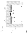
- FIG. 1 a first embodiment of a manufacturing device 10 according to the invention is shown.
- This manufacturing device 10 has an upper tool device 40.
- This upper tool device 40 is open at the bottom, and has a contour surface 42.
- This contour surface 42 has two first surface portions 20 and a second surface portion 30.
- the contour surface 42 can be both a rectangular and a round surface.
- the two first surface portions 20 behind the cross-sectional plane of FIG. 1 or before the cross-sectional level of FIG. 1 form a common first surface portion 20 which surrounds the second surface portion 30 substantially completely.
- each contour encoders 60 are provided in recesses in the upper tool device 40.
- These contour encoders 60 are located in the FIG. 1 in the non-extended state, and can as later will be explained in detail, are used to perform a deformation of a base decorative layer and / or an additional decorative layer can.
- vacuum channels of a vacuum device 50 are provided in the upper tool device 40.
- This vacuum device 50 has in the FIG. 1 a total of six channels, wherein two channels are in direct contact via an opening in each case with the second section 30.
- two channels per first surface section 20 are in fluid-communicating connection with this first surface section 20 via a microporous structure.
- the microporous structure is provided only in a region of the upper tool device 40 in order to keep the cost of this microporous structure as low as possible.
- the microporous structure is formed as a crosswise structure and may also be a separate insert in the upper tooling.
- the fluid-communicating connection over the remainder of the cross section of the upper tool device 40 is likewise represented via channels of the vacuum device 50. Not from FIG. 1 can be seen the connection of the vacuum device 50 with a vacuum pump, which negative pressure, so the suction of air, can make.
- an additional decoration layer 130 is shown below the upper tooling 40. Although this additional decorative layer 130 is already shown preformed, it is still in a substantially flexible state. In particular, in one embodiment as a fabric or leather for the additional decorative layer 130 is not a stable shape of the additional decorative layer 130 in the situation of FIG. 1 expected.
- the additional decoration layer 130 is applied in a first step to the second surface portion 30, so that a situation arises as in FIG. 2 is shown, in which the side of the additional decorative layer 130, which later forms part of a visible side of the finished decorative part 100, rests against the contour surface 42.
- a vacuum is applied via the central channels of the vacuum device 50, so that the additional decorative layer 130 held on the second section 30 is kept, so it remains sucked by a negative pressure.
- a clamping device 70 is used to deliver a strained base decor layer 120.
- the clamping device 70 is shown purely schematically. It is possible that individual clamping elements are provided, which the base decorative layer 120 in the tensioned situation as in FIG. 3 shown, hold. It is also possible that the tension of the base decorative layer 120 takes place only in cooperation with the upper tool device 40, as for example the FIG. 15 can be seen.
- the clamping device 70 and the upper tool device 40 are designed to be movable relative to each other and in particular from their in FIG. 3 shown positions to each other until a contacting of the base decorative layer 120 takes place with the upper tool device 40, as shown for example in FIG FIG.
- the side of the base decorative layer 120 which later also forms a portion of the visible side of the finished decorative part 100, rests against the contour surface 42.
- the air space between the base decorative layer 120 and the contour surface 42 of the upper tool device 40 is evacuated in a further step, this being carried out via the vacuum device 50.
- air is sucked off via the microporous structures and the channels lying behind them, so that a negative pressure is created between the base decorative layer 120 and the contour surface 42.
- a force is exerted on the base decorative layer 120 via this negative pressure, so that it is sucked in the direction of the contour surface 42.
- the evacuation is carried out until the base decoration layer 120 substantially completely abuts the first surface portions 20 and the remainder of the contour surface 42, respectively. After the application of the base decoration layer 120 to the first surface sections 20 or the contour surface 42, a state is reached as it is in FIG. 4 is shown. It is also possible that the tooling device 40 is completely or to a very large extent microporous.
- both the base decorative layer and the additional decorative layer are exclusively in the desired position by the negative pressure held. It may be that plastic deformations of the base decorative layer 120 and / or the additional decorative layer 130 have already been carried out by the negative pressure in order to produce the desired final shape of the decorative part 100.
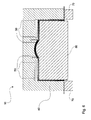
- FIG. 5 shows how in a further step provided for support support 110 is retracted into the upper tool device 40.
- a lower tool device 80 is provided, on which the carrier 110 is placed.
- the retraction is performed in such a way that the lower tool device 80 is adapted to the corresponding opening of the upper tool device 40, so that the preformed carrier 110 can be retracted.
- the retracted state of the carrier 110 is in FIG. 6 shown.
- the lower tool device 80 can advantageously additionally be pushed upwards, so that a contact pressure of the carrier 110 on the base decorative layer 120 and thus also indirectly on the additional decorative layer 130 takes place.
- a microstructure existing on the surface of the first surface portion 20 of the upper die device 40 is impressed in the upper surface of the base decoration layer 120.
- the force required for this is achieved both by the corresponding holding forces generated by negative pressure of the vacuum device 50, as well as by the pressing of the carrier 110 by means of the lower tool device 80.
- the negative pressure of the vacuum device 50 could already be switched off, so that the necessary support and also the necessary pressure are applied exclusively by the lower tool device 80 via the carrier 110.
- FIG. 7 the finished decorative part 100 is shown.
- the planar connection between the additional decorative layer 130 and the base decorative layer 120, or between the base decorative layer 120 and the carrier 110 was performed.
- an adhesive is used becomes.
- the base decor layer 120 has been heated prior to being drawn to the first portion 20. This can in particular already take place after the clamping in the clamping device 70, and be designed such that the base decoration layer 120 is essentially completely plasticized, which is the case, for example, at 180 to 220.degree.
- the carrier 110 in particular after it has been placed on the lower tool device 80, at least partially, in particular on its upper side facing the base decorative layer 120 side, have been melted.
- the carrier 110 advantageously consists of a polypropylene (PP) structure
- the base decorative layer 120 is advantageously constructed in multiple layers, in particular of thermoplastic polyolefins.
- the additional decorative layer 130 itself advantageously has at least one rear side, that is to say the base decorative layer 120 and the carrier 110, with a layer which is non-woven, in particular with polypropylene fibers.
- the plasticizing of the carrier 110 or of the base decorative layer 120 can also melt the additional decorative layer 130 onto its rear side, that is to say on the side facing the base decorative layer 120. After subsequent cooling, in this way a cohesive bond is formed in a flat manner between the additional decorative layer 130 and the base decorative layer 120 and the base decorative layer 120 and the carrier 110.
- no adhesive is required.
- a contour generator 60 The mode of operation of a contour generator 60 according to the invention will be explained with reference to the following figures.
- the additional decorative layer 130 is already applied to a second section 30 of the upper tool device 40.
- the base decor layer 120 is already applied to the associated first surface section 20 of the contour surface 42 of the upper tool device 40.
- the base decorative layer 120 has no cutout for the additional decorative layer 130, but rather lies completely on the surface Rear side of the same.
- the contour generator 60 is located in FIG. 8 still in the retracted state in which it has been substantially completely absorbed in the upper tool device 40. Shown in any of the figures is provided for the contour generator 60 movement mechanism, which may be provided for example via lever kinematics or other drives, such as gear, electric motors or magnetic drives.
- FIG. 9 shows the situation in which the contour generator 60 is in the extended position.
- the contour generator 60 moves downward, deforming both the base decoration layer 120 and the additional decoration layer 130.
- the deformation takes place in such a way that the base decoration layer 120 forms a groove, in particular a base decoration layer groove 122, by plastic deformation.
- the contour generator 60 in particular its contact surface 62, a.
- the edge portion of the additional decorative layer 130 is also introduced into the base decorative layer groove 122.
- the edge portion of the additional decorative layer 130 is moved to a position that is optically no longer visible after completion of a method according to the invention. This is done by the arrangement of the contour generator 60 in the connecting region between the two surface portions 20 and 30th
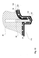
- FIG. 10 shows the subsequent process step.
- the formation of the base decoration layer groove 122 in the base decoration layer 120 is performed when the carrier 110 is not yet in the designated position on the back side of the base decoration layer 120.
- a carrier 110 Only after the base decorative layer groove 120 has been formed, for example approximately one second after its formation, can a carrier 110 be moved up from below in a further step, which already has a carrier groove 112 in prefabricated form.
- the carrier groove 112 is arranged such that it coincides when retracting the carrier 110 when it is applied to the back of the base decorative layer 120 with the position of the contour generator 60 and thus with the geometric expression of Basisdekortechnik 120.
- This correspondence is expressed by the fact that the base decorative layer groove 120 at least partially received in the carrier groove 112, as this FIG. 10 can be seen.
- the carrier groove 112 offers the possibility, despite the deformation of the base decorative layer 120, of allowing substantially full-surface application of the carrier 110 on the rear side of the base decorative layer 120.
- the contour generator 60 After applying the carrier 110 and after the subsequent cooling, or after waiting for solidification of the full-surface connection between carrier 110, base decorative layer 120 and additional decorative layer 130, the contour generator 60 is moved out again. He is thus as in FIG. 11 shown again in the initial position, ie the retracted position, and is ready for the next new process cycle.
- the groove in the base decoration layer 120 that is the base decoration layer groove 120, has been created by plastic deformation and therefore remains in the deformed position, as is the case for the additional decoration layer 130.
- a clean optical termination between the surface of the base decor layer 120 and the top surface of the additional decor layer 130 is possible.
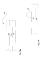
- FIG. 12a Each shows an embodiment of an additional decorative layer 130 and a base decorative layer 120 with regard to the choice of material.
- additional decorative layer 130 and base decorative layer 120 are multilayered.
- FIG. 12a In this case, the multilayer structure of an additional decorative layer 130 is shown. From bottom to top, this has a nonwoven layer 132, which is formed in particular of polypropylene-containing fibers. These polypropylene-containing fibers may be fused by an underfed warmed base decor layer 120 such that a material bond may be formed between this nonwoven layer 132 of the make layer 130 and a corresponding layer of the base decor layer 120.
- a foam layer 134 for example made of polyurethane foam. This polyurethane foam layer serves to improve the feel of the entire additional decorative layer 130.
- the decorative layer 136 for example a fabric or a leather, which has the desired optical and also haptic properties for the additional decorative layer 130, is located at the top.
- FIG. 12b shows an embodiment of a two-layer base decor layer 120.
- Both layers of the base decor layer 120 are formed substantially of thermoplastic olefin (TPO).
- the lower layer is likewise a foam layer 124, while the upper layer represents a decorative layer 126.
- the decorative layer 126 of the base decorative layer 120 is embodied, for example, of a lower quality than that of the additional decorative layer 130. In this way, a large area can be inexpensively decorated.
- TPO thermoplastic olefin
- FIG. 13 and 14 an embodiment of a decorative part 100 according to the invention is shown.
- the detail shows the respective grooves 112 and 122. These have been formed, as has already been explained in detail above.
- the contour generator 60 requires space in the base decoration layer groove 122. Due to the plastic deformation of the base decoration layer 120, this space remains after retraction of the contour generator 60, as in FIG FIG. 11 as a gap between the additional decorative layer 130 and the base decorative layer 120. To close this gap, the mechanism described below can be used.
- FIG. 13 shows the situation of the already connected base decorative layer 120 with the carrier 110, or already the planar connection between additional decorative layer 130 and base decorative layer 120. The connection is not shown here but is done in a material-locking manner as explained in detail.
- the foam layer 134 can expand. In other words, the thickness of the additional decorative layer 130 increases. This raises the additional decorative layer 130 in FIG. 14 in relation to FIG. 13 further upward, however, the gap in the base decorative layer groove 120 is also closed by the expansion of the foam layer 134. This results in an even more advantageous embodiment of a decorative part 100 according to the invention, since no gap remains which would be suitable for the absorption of dirt.
- FIG. 15 shows an embodiment of a sealing device according to the invention for the sealing between the clamping device 70 and the upper tool device 40.
- a nose-shaped latching projection is formed, which presses the base decorative layer 120 in a corresponding recess of the upper tool device 40.
- Two results are achieved.
- sealing takes place via the base decorative layer 120 itself, without the need for additional sealing means.
- pinching of the base decor layer 120 occurs, so that no subsequent flow of material during the application of the base decorative layer 120 on the contour surface 42 of the upper tool device 40 can take place. This ensures that a defined plastic deformation of the base decorative layer 120 is already carried out during the application process.
Landscapes
- Engineering & Computer Science (AREA)
- Manufacturing & Machinery (AREA)
- Laminated Bodies (AREA)
Applications Claiming Priority (1)
| Application Number | Priority Date | Filing Date | Title |
|---|---|---|---|
| DE201010034714 DE102010034714A1 (de) | 2010-08-18 | 2010-08-18 | Herstellvorrichtung für die Herstellung eines Dekorteils |
Publications (2)
| Publication Number | Publication Date |
|---|---|
| EP2420376A1 true EP2420376A1 (fr) | 2012-02-22 |
| EP2420376B1 EP2420376B1 (fr) | 2016-10-05 |
Family
ID=44680976
Family Applications (1)
| Application Number | Title | Priority Date | Filing Date |
|---|---|---|---|
| EP11006776.6A Not-in-force EP2420376B1 (fr) | 2010-08-18 | 2011-08-18 | Dispositif de fabrication d'un élément de décor et procédé |
Country Status (2)
| Country | Link |
|---|---|
| EP (1) | EP2420376B1 (fr) |
| DE (1) | DE102010034714A1 (fr) |
Cited By (1)
| Publication number | Priority date | Publication date | Assignee | Title |
|---|---|---|---|---|
| FR2975327A1 (fr) * | 2011-05-19 | 2012-11-23 | Faurecia Innenraum Sys Gmbh | Un outil de moulage, procede de formation d'un composant et d'un dispositif moule et procede pour ameliorer le maintien en place en position d'un element a realiser |
Families Citing this family (1)
| Publication number | Priority date | Publication date | Assignee | Title |
|---|---|---|---|---|
| DE102016219288B4 (de) | 2016-10-05 | 2025-02-27 | Bayerische Motoren Werke Aktiengesellschaft | Anzeigeelement mit Übergangskaschierung von partiellen Folien und Lackierungen |
Citations (4)
| Publication number | Priority date | Publication date | Assignee | Title |
|---|---|---|---|---|
| EP0569846A2 (fr) * | 1992-05-13 | 1993-11-18 | R + S STANZTECHNIK GmbH | Dispositif de fabrication de panneaux de revêtement et méthode de fixation de tels panneaux de revêtement sur un support |
| DE4305200A1 (de) * | 1993-02-19 | 1994-08-25 | Lignotock Gmbh | Verfahren zum Herstellen eines Innenverkleidungsteils mit hinterschäumter Kaschierfolie |
| US5830518A (en) * | 1993-08-16 | 1998-11-03 | Nissen Chemitec Corporation | Device for tucking covering materials |
| WO2007139865A2 (fr) * | 2006-05-25 | 2007-12-06 | Johnson Controls Technology Company | Article moulé comprenant un élément décoratif et procédé de fixation d'un élément décoratif à un composant de véhicule |
Family Cites Families (1)
| Publication number | Priority date | Publication date | Assignee | Title |
|---|---|---|---|---|
| DE8307414U1 (de) * | 1983-03-15 | 1985-10-31 | Audi AG, 8070 Ingolstadt | Innenverkleidungsteil, insbesondere für Fahrzeuge |
-
2010
- 2010-08-18 DE DE201010034714 patent/DE102010034714A1/de not_active Withdrawn
-
2011
- 2011-08-18 EP EP11006776.6A patent/EP2420376B1/fr not_active Not-in-force
Patent Citations (4)
| Publication number | Priority date | Publication date | Assignee | Title |
|---|---|---|---|---|
| EP0569846A2 (fr) * | 1992-05-13 | 1993-11-18 | R + S STANZTECHNIK GmbH | Dispositif de fabrication de panneaux de revêtement et méthode de fixation de tels panneaux de revêtement sur un support |
| DE4305200A1 (de) * | 1993-02-19 | 1994-08-25 | Lignotock Gmbh | Verfahren zum Herstellen eines Innenverkleidungsteils mit hinterschäumter Kaschierfolie |
| US5830518A (en) * | 1993-08-16 | 1998-11-03 | Nissen Chemitec Corporation | Device for tucking covering materials |
| WO2007139865A2 (fr) * | 2006-05-25 | 2007-12-06 | Johnson Controls Technology Company | Article moulé comprenant un élément décoratif et procédé de fixation d'un élément décoratif à un composant de véhicule |
Cited By (1)
| Publication number | Priority date | Publication date | Assignee | Title |
|---|---|---|---|---|
| FR2975327A1 (fr) * | 2011-05-19 | 2012-11-23 | Faurecia Innenraum Sys Gmbh | Un outil de moulage, procede de formation d'un composant et d'un dispositif moule et procede pour ameliorer le maintien en place en position d'un element a realiser |
Also Published As
| Publication number | Publication date |
|---|---|
| DE102010034714A1 (de) | 2012-02-23 |
| EP2420376B1 (fr) | 2016-10-05 |
Similar Documents
| Publication | Publication Date | Title |
|---|---|---|
| EP1799429B1 (fr) | Outil de moulage par pression et procede pour fabriquer une piece par moulage par pression | |
| EP1646492B2 (fr) | Elements de garniture interieure pour vehicules automobiles presentant un profil de surface defini | |
| DE2925500A1 (de) | Verfahren und vorrichtung zur herstellung von kaschierten formteilen | |
| DE102011055654A1 (de) | Herstellverfahren für ein Verbundblechteil mit metallischem Bereich | |
| DE19916023C2 (de) | Preßwerkzeug zur Herstellung von mit einer Folie bedeckten Formteilen | |
| EP0686476A2 (fr) | Procédé et appareil pour la fabrication d'un objet revêtu | |
| EP0657265B1 (fr) | Procédé de fabrication d'éléments plats revêtus utilisant des préformes en forme de grille | |
| EP2240311B1 (fr) | Procédé et appareil pour fabriquer un objet moulé | |
| EP2070680A1 (fr) | Dispositif et procédé destinés à la fabrication d'une pièce moulée dotée de plusieurs zones de décoration adjacentes différentes | |
| EP0581035A1 (fr) | Procédé pour la fabrication d'un objet moulé en matière plastique | |
| EP1970183B1 (fr) | Clapet d'airbag invisible, dispositif et son procédé de fabrication | |
| CH700688A2 (de) | Verfahren zur Herstellung eines mehrlagigen Formteils. | |
| EP2420376B1 (fr) | Dispositif de fabrication d'un élément de décor et procédé | |
| EP4100224B1 (fr) | Outil de moulage par injection et méthode de production de pièces moulées | |
| EP2744639A2 (fr) | Procédé et dispositif pour réaliser le revêtement partiel d'un élément, notamment d'une pièce de véhicule | |
| EP2632677A1 (fr) | Pièce composite et procédé de fabrication d'une pièce composite | |
| EP2556937B1 (fr) | Outil d'estampillage et de moussage ainsi que procédé | |
| DE10338109B4 (de) | Verfahren zur Herstellung eines Verbundbauteils | |
| WO2015035970A1 (fr) | Procédé de fabrication d'un produit au moyen d'une unité de thermoformage ou d'assemblage, et unité de thermoformage ou d'assemblage | |
| DE102004063657B4 (de) | Verfahren zur Herstellung eines Bauteils aus einer Dekorationsschicht und einer Trägerschicht | |
| EP3305497A1 (fr) | Moule et procédé pour la fabrication un article composite surmoulé | |
| DE102004045400B3 (de) | Verfahren zur Herstellung eines Bauteils aus zumindest zwei Schichten sowie eine Vorrichtung zur Durchführung des Verfahrens | |
| EP1645399B1 (fr) | Méthode et appareil pour la manifacture d'articles en plastique | |
| DE102023200002A1 (de) | Verfahren sowie Vorrichtung zur Herstellung eines Formteils | |
| DE19634840A1 (de) | Verfahren und Vorrichtung zur flächenhaften Aufbringung von Dekormaterial zur Verkleidung eines Formteils |
Legal Events
| Date | Code | Title | Description |
|---|---|---|---|
| AK | Designated contracting states |
Kind code of ref document: A1 Designated state(s): AL AT BE BG CH CY CZ DE DK EE ES FI FR GB GR HR HU IE IS IT LI LT LU LV MC MK MT NL NO PL PT RO RS SE SI SK SM TR |
|
| AX | Request for extension of the european patent |
Extension state: BA ME |
|
| PUAI | Public reference made under article 153(3) epc to a published international application that has entered the european phase |
Free format text: ORIGINAL CODE: 0009012 |
|
| 17P | Request for examination filed |
Effective date: 20120822 |
|
| GRAP | Despatch of communication of intention to grant a patent |
Free format text: ORIGINAL CODE: EPIDOSNIGR1 |
|
| INTG | Intention to grant announced |
Effective date: 20160128 |
|
| GRAS | Grant fee paid |
Free format text: ORIGINAL CODE: EPIDOSNIGR3 |
|
| GRAA | (expected) grant |
Free format text: ORIGINAL CODE: 0009210 |
|
| AK | Designated contracting states |
Kind code of ref document: B1 Designated state(s): AL AT BE BG CH CY CZ DE DK EE ES FI FR GB GR HR HU IE IS IT LI LT LU LV MC MK MT NL NO PL PT RO RS SE SI SK SM TR |
|
| REG | Reference to a national code |
Ref country code: GB Ref legal event code: FG4D Free format text: NOT ENGLISH |
|
| REG | Reference to a national code |
Ref country code: CH Ref legal event code: EP |
|
| REG | Reference to a national code |
Ref country code: AT Ref legal event code: REF Ref document number: 834235 Country of ref document: AT Kind code of ref document: T Effective date: 20161015 |
|
| REG | Reference to a national code |
Ref country code: IE Ref legal event code: FG4D Free format text: LANGUAGE OF EP DOCUMENT: GERMAN |
|
| REG | Reference to a national code |
Ref country code: DE Ref legal event code: R096 Ref document number: 502011010814 Country of ref document: DE |
|
| REG | Reference to a national code |
Ref country code: NL Ref legal event code: MP Effective date: 20161005 |
|
| REG | Reference to a national code |
Ref country code: LT Ref legal event code: MG4D |
|
| PG25 | Lapsed in a contracting state [announced via postgrant information from national office to epo] |
Ref country code: LV Free format text: LAPSE BECAUSE OF FAILURE TO SUBMIT A TRANSLATION OF THE DESCRIPTION OR TO PAY THE FEE WITHIN THE PRESCRIBED TIME-LIMIT Effective date: 20161005 |
|
| PG25 | Lapsed in a contracting state [announced via postgrant information from national office to epo] |
Ref country code: SE Free format text: LAPSE BECAUSE OF FAILURE TO SUBMIT A TRANSLATION OF THE DESCRIPTION OR TO PAY THE FEE WITHIN THE PRESCRIBED TIME-LIMIT Effective date: 20161005 Ref country code: GR Free format text: LAPSE BECAUSE OF FAILURE TO SUBMIT A TRANSLATION OF THE DESCRIPTION OR TO PAY THE FEE WITHIN THE PRESCRIBED TIME-LIMIT Effective date: 20170106 Ref country code: LT Free format text: LAPSE BECAUSE OF FAILURE TO SUBMIT A TRANSLATION OF THE DESCRIPTION OR TO PAY THE FEE WITHIN THE PRESCRIBED TIME-LIMIT Effective date: 20161005 Ref country code: NO Free format text: LAPSE BECAUSE OF FAILURE TO SUBMIT A TRANSLATION OF THE DESCRIPTION OR TO PAY THE FEE WITHIN THE PRESCRIBED TIME-LIMIT Effective date: 20170105 |
|
| PG25 | Lapsed in a contracting state [announced via postgrant information from national office to epo] |
Ref country code: HR Free format text: LAPSE BECAUSE OF FAILURE TO SUBMIT A TRANSLATION OF THE DESCRIPTION OR TO PAY THE FEE WITHIN THE PRESCRIBED TIME-LIMIT Effective date: 20161005 Ref country code: ES Free format text: LAPSE BECAUSE OF FAILURE TO SUBMIT A TRANSLATION OF THE DESCRIPTION OR TO PAY THE FEE WITHIN THE PRESCRIBED TIME-LIMIT Effective date: 20161005 Ref country code: PT Free format text: LAPSE BECAUSE OF FAILURE TO SUBMIT A TRANSLATION OF THE DESCRIPTION OR TO PAY THE FEE WITHIN THE PRESCRIBED TIME-LIMIT Effective date: 20170206 Ref country code: FI Free format text: LAPSE BECAUSE OF FAILURE TO SUBMIT A TRANSLATION OF THE DESCRIPTION OR TO PAY THE FEE WITHIN THE PRESCRIBED TIME-LIMIT Effective date: 20161005 Ref country code: PL Free format text: LAPSE BECAUSE OF FAILURE TO SUBMIT A TRANSLATION OF THE DESCRIPTION OR TO PAY THE FEE WITHIN THE PRESCRIBED TIME-LIMIT Effective date: 20161005 Ref country code: RS Free format text: LAPSE BECAUSE OF FAILURE TO SUBMIT A TRANSLATION OF THE DESCRIPTION OR TO PAY THE FEE WITHIN THE PRESCRIBED TIME-LIMIT Effective date: 20161005 Ref country code: IS Free format text: LAPSE BECAUSE OF FAILURE TO SUBMIT A TRANSLATION OF THE DESCRIPTION OR TO PAY THE FEE WITHIN THE PRESCRIBED TIME-LIMIT Effective date: 20170205 Ref country code: NL Free format text: LAPSE BECAUSE OF FAILURE TO SUBMIT A TRANSLATION OF THE DESCRIPTION OR TO PAY THE FEE WITHIN THE PRESCRIBED TIME-LIMIT Effective date: 20161005 |
|
| REG | Reference to a national code |
Ref country code: DE Ref legal event code: R097 Ref document number: 502011010814 Country of ref document: DE |
|
| REG | Reference to a national code |
Ref country code: FR Ref legal event code: PLFP Year of fee payment: 7 |
|
| PG25 | Lapsed in a contracting state [announced via postgrant information from national office to epo] |
Ref country code: RO Free format text: LAPSE BECAUSE OF FAILURE TO SUBMIT A TRANSLATION OF THE DESCRIPTION OR TO PAY THE FEE WITHIN THE PRESCRIBED TIME-LIMIT Effective date: 20161005 Ref country code: DK Free format text: LAPSE BECAUSE OF FAILURE TO SUBMIT A TRANSLATION OF THE DESCRIPTION OR TO PAY THE FEE WITHIN THE PRESCRIBED TIME-LIMIT Effective date: 20161005 Ref country code: EE Free format text: LAPSE BECAUSE OF FAILURE TO SUBMIT A TRANSLATION OF THE DESCRIPTION OR TO PAY THE FEE WITHIN THE PRESCRIBED TIME-LIMIT Effective date: 20161005 Ref country code: CZ Free format text: LAPSE BECAUSE OF FAILURE TO SUBMIT A TRANSLATION OF THE DESCRIPTION OR TO PAY THE FEE WITHIN THE PRESCRIBED TIME-LIMIT Effective date: 20161005 Ref country code: SK Free format text: LAPSE BECAUSE OF FAILURE TO SUBMIT A TRANSLATION OF THE DESCRIPTION OR TO PAY THE FEE WITHIN THE PRESCRIBED TIME-LIMIT Effective date: 20161005 |
|
| PLBE | No opposition filed within time limit |
Free format text: ORIGINAL CODE: 0009261 |
|
| STAA | Information on the status of an ep patent application or granted ep patent |
Free format text: STATUS: NO OPPOSITION FILED WITHIN TIME LIMIT |
|
| PG25 | Lapsed in a contracting state [announced via postgrant information from national office to epo] |
Ref country code: BG Free format text: LAPSE BECAUSE OF FAILURE TO SUBMIT A TRANSLATION OF THE DESCRIPTION OR TO PAY THE FEE WITHIN THE PRESCRIBED TIME-LIMIT Effective date: 20170105 Ref country code: IT Free format text: LAPSE BECAUSE OF FAILURE TO SUBMIT A TRANSLATION OF THE DESCRIPTION OR TO PAY THE FEE WITHIN THE PRESCRIBED TIME-LIMIT Effective date: 20161005 Ref country code: SM Free format text: LAPSE BECAUSE OF FAILURE TO SUBMIT A TRANSLATION OF THE DESCRIPTION OR TO PAY THE FEE WITHIN THE PRESCRIBED TIME-LIMIT Effective date: 20161005 |
|
| 26N | No opposition filed |
Effective date: 20170706 |
|
| PG25 | Lapsed in a contracting state [announced via postgrant information from national office to epo] |
Ref country code: SI Free format text: LAPSE BECAUSE OF FAILURE TO SUBMIT A TRANSLATION OF THE DESCRIPTION OR TO PAY THE FEE WITHIN THE PRESCRIBED TIME-LIMIT Effective date: 20161005 |
|
| REG | Reference to a national code |
Ref country code: CH Ref legal event code: PL |
|
| PG25 | Lapsed in a contracting state [announced via postgrant information from national office to epo] |
Ref country code: MC Free format text: LAPSE BECAUSE OF FAILURE TO SUBMIT A TRANSLATION OF THE DESCRIPTION OR TO PAY THE FEE WITHIN THE PRESCRIBED TIME-LIMIT Effective date: 20161005 |
|
| GBPC | Gb: european patent ceased through non-payment of renewal fee |
Effective date: 20170818 |
|
| PG25 | Lapsed in a contracting state [announced via postgrant information from national office to epo] |
Ref country code: LI Free format text: LAPSE BECAUSE OF NON-PAYMENT OF DUE FEES Effective date: 20170831 Ref country code: CH Free format text: LAPSE BECAUSE OF NON-PAYMENT OF DUE FEES Effective date: 20170831 |
|
| REG | Reference to a national code |
Ref country code: IE Ref legal event code: MM4A |
|
| REG | Reference to a national code |
Ref country code: BE Ref legal event code: MM Effective date: 20170831 |
|
| PG25 | Lapsed in a contracting state [announced via postgrant information from national office to epo] |
Ref country code: LU Free format text: LAPSE BECAUSE OF NON-PAYMENT OF DUE FEES Effective date: 20170818 |
|
| REG | Reference to a national code |
Ref country code: FR Ref legal event code: PLFP Year of fee payment: 8 |
|
| PG25 | Lapsed in a contracting state [announced via postgrant information from national office to epo] |
Ref country code: IE Free format text: LAPSE BECAUSE OF NON-PAYMENT OF DUE FEES Effective date: 20170818 Ref country code: GB Free format text: LAPSE BECAUSE OF NON-PAYMENT OF DUE FEES Effective date: 20170818 |
|
| PG25 | Lapsed in a contracting state [announced via postgrant information from national office to epo] |
Ref country code: BE Free format text: LAPSE BECAUSE OF NON-PAYMENT OF DUE FEES Effective date: 20170831 |
|
| PG25 | Lapsed in a contracting state [announced via postgrant information from national office to epo] |
Ref country code: MT Free format text: LAPSE BECAUSE OF FAILURE TO SUBMIT A TRANSLATION OF THE DESCRIPTION OR TO PAY THE FEE WITHIN THE PRESCRIBED TIME-LIMIT Effective date: 20161005 |
|
| REG | Reference to a national code |
Ref country code: AT Ref legal event code: MM01 Ref document number: 834235 Country of ref document: AT Kind code of ref document: T Effective date: 20170818 |
|
| PG25 | Lapsed in a contracting state [announced via postgrant information from national office to epo] |
Ref country code: AT Free format text: LAPSE BECAUSE OF NON-PAYMENT OF DUE FEES Effective date: 20170818 |
|
| PG25 | Lapsed in a contracting state [announced via postgrant information from national office to epo] |
Ref country code: HU Free format text: LAPSE BECAUSE OF FAILURE TO SUBMIT A TRANSLATION OF THE DESCRIPTION OR TO PAY THE FEE WITHIN THE PRESCRIBED TIME-LIMIT; INVALID AB INITIO Effective date: 20110818 |
|
| PG25 | Lapsed in a contracting state [announced via postgrant information from national office to epo] |
Ref country code: CY Free format text: LAPSE BECAUSE OF NON-PAYMENT OF DUE FEES Effective date: 20161005 |
|
| PG25 | Lapsed in a contracting state [announced via postgrant information from national office to epo] |
Ref country code: MK Free format text: LAPSE BECAUSE OF FAILURE TO SUBMIT A TRANSLATION OF THE DESCRIPTION OR TO PAY THE FEE WITHIN THE PRESCRIBED TIME-LIMIT Effective date: 20161005 |
|
| PG25 | Lapsed in a contracting state [announced via postgrant information from national office to epo] |
Ref country code: TR Free format text: LAPSE BECAUSE OF FAILURE TO SUBMIT A TRANSLATION OF THE DESCRIPTION OR TO PAY THE FEE WITHIN THE PRESCRIBED TIME-LIMIT Effective date: 20161005 |
|
| PG25 | Lapsed in a contracting state [announced via postgrant information from national office to epo] |
Ref country code: AL Free format text: LAPSE BECAUSE OF FAILURE TO SUBMIT A TRANSLATION OF THE DESCRIPTION OR TO PAY THE FEE WITHIN THE PRESCRIBED TIME-LIMIT Effective date: 20161005 |
|
| PGFP | Annual fee paid to national office [announced via postgrant information from national office to epo] |
Ref country code: FR Payment date: 20200721 Year of fee payment: 10 |
|
| REG | Reference to a national code |
Ref country code: DE Ref legal event code: R082 Ref document number: 502011010814 Country of ref document: DE Representative=s name: PFENNING, MEINIG & PARTNER MBB PATENTANWAELTE, DE |
|
| PG25 | Lapsed in a contracting state [announced via postgrant information from national office to epo] |
Ref country code: FR Free format text: LAPSE BECAUSE OF NON-PAYMENT OF DUE FEES Effective date: 20210831 |
|
| PGFP | Annual fee paid to national office [announced via postgrant information from national office to epo] |
Ref country code: DE Payment date: 20240723 Year of fee payment: 14 |
|
| REG | Reference to a national code |
Ref country code: DE Ref legal event code: R119 Ref document number: 502011010814 Country of ref document: DE |