EP2420422A2 - Procédé destiné au fonctionnement d'un système de réglage de la vitesse d'un véhicule automobile et véhicule automobile - Google Patents
Procédé destiné au fonctionnement d'un système de réglage de la vitesse d'un véhicule automobile et véhicule automobile Download PDFInfo
- Publication number
- EP2420422A2 EP2420422A2 EP11006110A EP11006110A EP2420422A2 EP 2420422 A2 EP2420422 A2 EP 2420422A2 EP 11006110 A EP11006110 A EP 11006110A EP 11006110 A EP11006110 A EP 11006110A EP 2420422 A2 EP2420422 A2 EP 2420422A2
- Authority
- EP
- European Patent Office
- Prior art keywords
- vehicle
- speed
- reference vehicle
- driver
- sensor
- Prior art date
- Legal status (The legal status is an assumption and is not a legal conclusion. Google has not performed a legal analysis and makes no representation as to the accuracy of the status listed.)
- Withdrawn
Links
Images

Classifications
-
- B—PERFORMING OPERATIONS; TRANSPORTING
- B60—VEHICLES IN GENERAL
- B60W—CONJOINT CONTROL OF VEHICLE SUB-UNITS OF DIFFERENT TYPE OR DIFFERENT FUNCTION; CONTROL SYSTEMS SPECIALLY ADAPTED FOR HYBRID VEHICLES; ROAD VEHICLE DRIVE CONTROL SYSTEMS FOR PURPOSES NOT RELATED TO THE CONTROL OF A PARTICULAR SUB-UNIT
- B60W30/00—Purposes of road vehicle drive control systems not related to the control of a particular sub-unit, e.g. of systems using conjoint control of vehicle sub-units
- B60W30/14—Adaptive cruise control
- B60W30/16—Control of distance between vehicles, e.g. keeping a distance to preceding vehicle
-
- B—PERFORMING OPERATIONS; TRANSPORTING
- B60—VEHICLES IN GENERAL
- B60W—CONJOINT CONTROL OF VEHICLE SUB-UNITS OF DIFFERENT TYPE OR DIFFERENT FUNCTION; CONTROL SYSTEMS SPECIALLY ADAPTED FOR HYBRID VEHICLES; ROAD VEHICLE DRIVE CONTROL SYSTEMS FOR PURPOSES NOT RELATED TO THE CONTROL OF A PARTICULAR SUB-UNIT
- B60W30/00—Purposes of road vehicle drive control systems not related to the control of a particular sub-unit, e.g. of systems using conjoint control of vehicle sub-units
- B60W30/14—Adaptive cruise control
- B60W30/143—Speed control
-
- B—PERFORMING OPERATIONS; TRANSPORTING
- B60—VEHICLES IN GENERAL
- B60W—CONJOINT CONTROL OF VEHICLE SUB-UNITS OF DIFFERENT TYPE OR DIFFERENT FUNCTION; CONTROL SYSTEMS SPECIALLY ADAPTED FOR HYBRID VEHICLES; ROAD VEHICLE DRIVE CONTROL SYSTEMS FOR PURPOSES NOT RELATED TO THE CONTROL OF A PARTICULAR SUB-UNIT
- B60W50/00—Details of control systems for road vehicle drive control not related to the control of a particular sub-unit, e.g. process diagnostic or vehicle driver interfaces
- B60W50/08—Interaction between the driver and the control system
- B60W50/082—Selecting or switching between different modes of propelling
-
- B—PERFORMING OPERATIONS; TRANSPORTING
- B60—VEHICLES IN GENERAL
- B60W—CONJOINT CONTROL OF VEHICLE SUB-UNITS OF DIFFERENT TYPE OR DIFFERENT FUNCTION; CONTROL SYSTEMS SPECIALLY ADAPTED FOR HYBRID VEHICLES; ROAD VEHICLE DRIVE CONTROL SYSTEMS FOR PURPOSES NOT RELATED TO THE CONTROL OF A PARTICULAR SUB-UNIT
- B60W50/00—Details of control systems for road vehicle drive control not related to the control of a particular sub-unit, e.g. process diagnostic or vehicle driver interfaces
- B60W50/08—Interaction between the driver and the control system
- B60W50/10—Interpretation of driver requests or demands
-
- B—PERFORMING OPERATIONS; TRANSPORTING
- B60—VEHICLES IN GENERAL
- B60K—ARRANGEMENT OR MOUNTING OF PROPULSION UNITS OR OF TRANSMISSIONS IN VEHICLES; ARRANGEMENT OR MOUNTING OF PLURAL DIVERSE PRIME-MOVERS IN VEHICLES; AUXILIARY DRIVES FOR VEHICLES; INSTRUMENTATION OR DASHBOARDS FOR VEHICLES; ARRANGEMENTS IN CONNECTION WITH COOLING, AIR INTAKE, GAS EXHAUST OR FUEL SUPPLY OF PROPULSION UNITS IN VEHICLES
- B60K35/00—Instruments specially adapted for vehicles; Arrangement of instruments in or on vehicles
- B60K35/60—Instruments characterised by their location or relative disposition in or on vehicles
-
- B—PERFORMING OPERATIONS; TRANSPORTING
- B60—VEHICLES IN GENERAL
- B60K—ARRANGEMENT OR MOUNTING OF PROPULSION UNITS OR OF TRANSMISSIONS IN VEHICLES; ARRANGEMENT OR MOUNTING OF PLURAL DIVERSE PRIME-MOVERS IN VEHICLES; AUXILIARY DRIVES FOR VEHICLES; INSTRUMENTATION OR DASHBOARDS FOR VEHICLES; ARRANGEMENTS IN CONNECTION WITH COOLING, AIR INTAKE, GAS EXHAUST OR FUEL SUPPLY OF PROPULSION UNITS IN VEHICLES
- B60K37/00—Dashboards
- B60K37/20—Dashboard panels
-
- B—PERFORMING OPERATIONS; TRANSPORTING
- B60—VEHICLES IN GENERAL
- B60W—CONJOINT CONTROL OF VEHICLE SUB-UNITS OF DIFFERENT TYPE OR DIFFERENT FUNCTION; CONTROL SYSTEMS SPECIALLY ADAPTED FOR HYBRID VEHICLES; ROAD VEHICLE DRIVE CONTROL SYSTEMS FOR PURPOSES NOT RELATED TO THE CONTROL OF A PARTICULAR SUB-UNIT
- B60W2540/00—Input parameters relating to occupants
- B60W2540/12—Brake pedal position
Definitions
- the invention relates to a method for operating a speed control system of a motor vehicle, wherein in a normal operating mode, the speed of the motor vehicle is controlled to a driver-selectable desired speed, and a motor vehicle with a speed control system.
- Speed control systems (often also known as speed control system - GRA) are known today and already used in many motor vehicles. The basic idea of such a speed control system is that the driver sets a desired speed, for example a currently driven speed, and the motor vehicle then takes such an intervention on the control of the motor that the desired speed is kept as exact as possible.
- Cruise control systems are especially popular because the costs are very low, since the function can be implemented in the engine control unit and only an additional control unit, such as a lever or a control unit on the steering wheel, is needed.
- speed control systems are an easy-to-understand driver assistance system for the driver.
- the invention is therefore based on the object to provide an extension of the functionality of a cruise control system, which allows a simple and by the driver certain way a more comfortable use of the cruise control system in areas of high vehicle density.
- a follower mode in response to a predetermined driver-side operating action in a detected by means of at least one environment sensor reference vehicle on the same lane a follower mode is activated, in which at slower than the desired speed moving reference vehicle a temporal or spatial distance, in particular a time gap, is regulated to the reference vehicle.
- a favorable environment sensor system in order to allow an extension of the function of the speed control system to a docking mode or subsequent operating mode.
- the normal operating mode of the cruise control system is used, so there is known as a control mode in which a selected by the driver's desired speed is maintained by the system. It may optionally be provided that this desired speed can be increased or decreased via at least one control element.
- An approach to a vehicle in front can therefore be overcome in the context of the method according to the invention by either terminating the control process of the speed control system present in the normal operating mode, traveling behind the object in following drive and reactivating the speed control system in the following operating mode, or one can, in particular at lower differential speeds, even when the normal operating mode is active, perform the operating action. In both cases, the consequence is that the reference vehicle is then followed.
- the customer benefit of a cruise control system is increased by using at least one environmental sensor, in particular having a minimum detection range of about 100 m, and adding a sequential mode of operation that allows convenient use of the cruise control system on high traffic density roads.
- the system limits are kept simple, because in addition to the standard function of the cruise control system, the normal operating mode, there is only the driver-initiated distance control in the subsequent operating mode. There is a consistent system performance, so no daily performance. The approach performance is always the same, since there is no gap control without driver initialization. Secondary lane disorders are becoming widespread avoided.
- the concept described here can be used advantageously throughout the entire speed range.
- the subsequent operating mode is at least partially deactivated in favor of the normal operating mode as soon as the reference vehicle as the deactivation condition faster than the desired speed travels and / or leaves the detection range of the environmental sensor and / or the own lane.
- the reference vehicle can thus serve as a follow-up object until it is removed again (the speed of the reference vehicle is therefore greater than its own desired speed and the reference vehicle moves out of the sensor detection area) or it leaves the drive lane, ie the current traffic lane. Then it is possible to switch back to the normal operating mode, whereby, of course, other embodiments, which may be dependent on further parameters, are also conceivable.
- a follow-up object falls away, for example by changing the lane
- Such a vehicle can then be taken over as a new reference vehicle, where, if appropriate, other or further conditions may be given, as will be discussed in more detail below.
- the speed control system can automatically search for a new destination, which then serves as a new reference vehicle. It is particularly advantageous to control the same time or space desired distance, which has already been selected with respect to the previous reference vehicle. So the conditions of the subsequent journey practically do not change.
- the third vehicle upon detection of a third vehicle located closer to the own vehicle than the reference vehicle in its own lane, the third vehicle is regulated as a new reference vehicle, in particular with the same distance, by means of the at least one surroundings sensor. Even if the reference vehicle can still be detected, however, it can be checked whether, for example, a third vehicle has already been cut in between the reference vehicle and its own motor vehicle on its own lane, which offers itself as a new reference vehicle.
- a regulation to a new reference vehicle instead of a termination of the subsequent operating mode is only performed if the new reference vehicle has a speed lying in its own speed within a certain speed range, in particular the speed of the new reference vehicle maximum at 10 km / h from your own speed differs.
- speed limit that is not recognizable for the customer, it is ensured in this way that, within the scope of the control possibilities of the speed control system, a sufficiently rapid adjustment to the distance to the new reference vehicle is made possible.
- a system operating element in particular a resume operating element or a speed-setting operating element, and / or the actuation of the brake is used as the driver's operating action. It is therefore fundamentally conceivable to occupy several existing control elements of the speed control system several times in order to enable the activation of the subsequent operating mode.
- a resume control element or a speed set button (set) can be used for this purpose.
- an actuation of the brake of the motor vehicle serves as an operating action. If, for example, you are traveling in the normal operating mode and driving on a slower moving vehicle, so a manual braking is necessary.
- the speed control system can automatically activate after release of the brake again in the subsequent operating mode and the vehicle, on the basis of which the braking intervention took place, as a reference vehicle, so follow object, select and follow this as already described above.
- the fact that the driver brakes with respect to a slower moving vehicle is understood in this case as an operating action to highly comfortable for the driver to activate the subsequent operating mode, if necessary, as long as the motor vehicle is present, then also automatically back to the Desired speed in normal operating mode to be able to control.
- the distance, in particular as a time gap, at the time of the operator action present distance, in particular the present at the time of the operating action Leitlücke is selected. While the time gap is usually used as a controlled variable during follow-up runs, it is also fundamentally advantageous to choose in the method according to the invention. It can now be provided that the situation at the time of the operating action is considered as a distance, in particular as a time gap.
- the speed control system takes over the distance (the time gap) at the time of the docking operation of the driver and tries to regulate this in the following drive. In this embodiment, the driver can later by simply trespassing and the associated approach and by re-performing the operation shorten the control distance or by manually increasing the distance and then re-docking the control distance also increase.
- the distance is changed when the driver side actuation of at least one distance control element, in particular a lever. So it is also possible, similar to the subsequent adjustment of the desired speed, to allow a subsequent adjustment of the distance, in particular the time gap, by the driver, for example by providing a "plus” and a "minus” button or one in two different directions operable lever is used to adjust the desired distance can arbitrarily.
- the distance to which the reference vehicle is to be regulated is preselected on the driver side.
- the driver can already deposit a desired distance, which is ideal for him, in the speed control system so that it can continue to be used each time the subsequent operating mode is activated.
- the control distance is therefore independent of the distance that is present at the time of docking operation, ie the operating action.
- the subsequent operating mode in general in the present invention refers purely to the longitudinal guide.
- the activity of the subsequent operating mode is indicated by a display element, in particular a backlit vehicle symbol adjacent to an activity display for the speed control system.
- a display element in particular a backlit vehicle symbol adjacent to an activity display for the speed control system.
- a general activity symbol for the speed control system for example a GRA symbol
- a further symbol for example a green vehicle next to the activation symbol
- it may also be provided to provide a display element which indicates that a possible reference vehicle has been detected and it is now possible to dock on it by performing the operating action and to activate the follow-up mode. Visible various display concepts are conceivable to bring the current state of the cruise control system and the controls to the driver's attention.
- a driver takeover request when a maximum exceeded by the speed control system triggerable limit brake delay is given by the currently required to maintain the distance brake delay a driver takeover request and the speed control system is deactivated.
- the cruise control system is a comfort system
- the anticipated braking deceleration may be limited, for example, by a maximum limit braking deceleration.
- a driver takeover request can be made, for example by an acoustic indication, in particular a gong, sounds in the motor vehicle and / or a status symbol, in particular a GRA symbol, is illuminated red or the like.
- an environmental sensor with a detection range of at least 100 m, in particular 150 m, can be used.
- a sensor which is already installed in the motor vehicle and is used for at least one further vehicle system, in particular a safety system, can be used.
- an environment sensor can be used that is already installed in the motor vehicle for one or more safety systems, for example for an inner-city pre-crash system and / or a brake assistance system.
- Such environmental sensors usually also have the aforementioned detection ranges of at least 100 m.
- the method according to the invention can be realized particularly favorably, since the environment sensor is already installed for a safety function in the motor vehicle anyway.
- the environment sensor is already installed for a safety function in the motor vehicle anyway.
- built-in controls anyway used in particular the brake pedal, so no additional controls must be added.
- At least one further surroundings sensor can be used, in particular for improving the lane allocation of detected motor vehicles, and / or a radar sensor and / or a lidar sensor and / or a PMD sensor and / or a camera can be used and / or used as surroundings sensor for evaluating the sensor data, data of further vehicle systems, in particular of a navigation system or of a sensor system, which detects, for example, lines such as lane boundaries, are taken into account.
- the mentioned types of environmental sensors are common, low-cost environment sensors that can also be used for the inventive method.
- a control unit of the speed control system then receives the sensor data, which may have already been prepared, and selects these as part of the functionalities described.
- a so-called environmental model is already determined from the data of the environment sensors installed in the motor vehicle, information about their occupancy is assigned in the various positions around the motor vehicle. From such an environment model can be queried by the speed control system optionally specifically the necessary information to determine, for example, the existence of a possible reference vehicle or in the subsequent operating mode of its relevant properties.
- the speed control system optionally specifically the necessary information to determine, for example, the existence of a possible reference vehicle or in the subsequent operating mode of its relevant properties.
- a tachometer ring is used to display the desired speed.
- a display on the tachometer itself, in particular on a tachometer ring is particularly advantageous used.
- the invention also relates to a motor vehicle, comprising a speed control system with a control unit designed for carrying out the method according to the invention. All statements with regard to the method according to the invention can be analogously applied to the motor vehicle according to the invention, with which consequently the same advantages as in the method according to the invention can be achieved.
- the motor vehicle additionally also comprises at least one environment sensor, on whose possibly processed sensor data the speed control system can access as required.
- the speed control system may include its own controls and display elements, but possibly also to other controls, such as a brake pedal with respect to the operating action, access.
- a display means various, the operating state of the speed control system indicating, in particular backlit symbols can be provided, in addition, a tachometer ring can also be used to represent the desired speed.
- Various embodiments are conceivable here.
- Fig. 1 It shows a schematic diagram of a motor vehicle 1 according to the invention. It comprises a speed control system 2 with a control unit 3, which is designed to regulate in a normal operating mode to a desired speed predetermined by the driver of the motor vehicle 1. In the present case, however, the control unit 3 is also designed to operate the speed control system 2 in a subsequent operating mode.
- control unit 3 which need not be assigned solely to the speed control system 2, by the way, but also another control unit, such as an engine control unit, with additional functionality may be access to the data from environment sensors 4, of which several are shown here by way of example.
- the environment sensors 4 may be, for example, radar sensors, lidar sensors, PMD sensors, cameras or other environment sensors.
- the environmental sensors 4 at least partially have a detection range which is greater than, for example, 100 m.
- the data of further, indicated at 5 vehicle systems can be processed and taken into account by the control unit 3, for example, the data of a navigation system.
- a bus system 6 for example a CAN bus.
- the environmental sensors 4 can also be assigned to other vehicle systems, in particular at least one safety system, for example a brake assistance system or a pre-crash system.
- the control unit 3 is now adapted to check in a predetermined operator action of the driver, whether the motor vehicle 1 is currently in follow-on, which means that a reference vehicle, followed by the motor vehicle 1, is in its own lane and moves. If this is the case, the subsequent operating mode is activated, and it is controlled by a certain time gap to the reference vehicle, instead of as in normal operation mode inevitably the desired speed is maintained. In the subsequent operating mode, it is therefore the distance, here the time gap, to which is regulated; For this purpose, of course, data of the environment sensors 4 are used.
- Fig. 2 shows by way of example possible implementations of control and display elements that may find application in the present invention.
- an instrument panel 7 is provided, on which a GRA symbol 8 and a vehicle symbol 9 are provided.
- the symbols 8, 9 can be backlit in different colors. If, for example, the normal operating mode is active, then the GRA symbol 8 can be backlit in green, but the vehicle symbol 9 is dark. If the subsequent operating mode is activated, the vehicle symbol 9 can also be backlit in green. It is also conceivable within the scope of the present invention to backlight the vehicle symbol 9 in a different color, for example in yellow, or flashing, if a possible reference vehicle has been detected by the environmental sensors 4 and thus activating the subsequent operating mode by the driver to be performed operating action is possible.
- the symbols 8, 9 may continue to be used. to display a driver takeover request to be performed with subsequent deactivation of the cruise control system 2.
- the symbols 8, 9 are backlit red and it can be an audible signal, for example, a gong, sound.
- voice announcements or the like are examples of other ways to issue a Fahrüberewedaufgrad.
- an analog tachometer 10 is further arranged, which is surrounded by a subdivided into a plurality of segments tachometer ring 11.
- the segments of the tachometer ring 11 are individually illuminated and are used to display the currently set desired speed for the normal operating mode. Because the desired speed is maintained even in the subsequent operating mode, while the actual speed of the motor vehicle 1 can fall below the desired speed, so that by means of the tachometer ring 11 the driver still set the currently set desired speed continues to notice.
- the speed control system 2 is also assigned as a control lever 12, which may be arranged for example on the steering wheel. By moving the lever up and down, the desired speed can be gradually increased and decreased. On the lever 12 is realized as an additional adjustment but also that by movement of the lever 12, which is possible for example only when activated subsequent operating mode, the time gap to which is regulated, so the desired distance can be increased or decreased. Thus, operating parameters of the speed control system 2 via the lever 12 can be adjusted in a comfortable manner. On the steering wheel or laterally next to the instrument panel 7 may be arranged as further controls buttons 13, 14, here a speed control element 13 and a resume control element 14. In addition to their usual function, these controls can also be designed so that their operation than the predetermined Operating action for activating the subsequent operating mode is used.
- a preset desired distance ie a pre-set desired time gap to use, which can also be entered via specific controls. This is then basically used in the next operating mode.
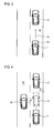
- Fig. 3 shows the motor vehicle 1 according to the invention, as it approaches the desired speed, arrow 15, an in the same lane 16 preceding vehicle 17 when activated normal operating mode.
- the driver operates the brake to decelerate to the preceding vehicle 17, as indicated by the arrow 18.
- This actuation of the brake is now understood in the embodiment described herein as a predetermined operator action for driver-initiated activation of the subsequent operating mode.
- the normal operating mode is deactivated as usual when the brake is actuated, it is simultaneously checked by the control unit 3 on the basis of the data from the environmental sensors 4 as to whether this braking has been triggered by a vehicle 17 possibly suitable as a reference vehicle. This is obviously the case here. Accordingly, after completion of the braking operation, the speed control system 2 switches to the following operation mode with the vehicle 17 serving as a reference vehicle.
- the desired distance there are two main options for selecting the desired distance, in this case the desired time gap.
- the time gap at the time of the operating action is used as the desired time gap; It is thus regulated to the distance in which the driver braked the motor vehicle 1 on the preceding motor vehicle 17.
- the lever 12 can be used. But it is also possible that the driver makes his own distance by his own acceleration or braking maneuver, then again to activate the subsequent operating mode by or one of the predetermined operator actions. It should also be noted at this point that it is of course also possible to activate the subsequent operating mode by different operating actions, for example by a braking operation, as with respect to Fig. 3 just described, or by pressing the button 13 and / or 14.
- Fig. 4 shows a further traffic situation, in which it is assumed that the motor vehicle 1 with the activated in the subsequent operating mode cruise control system 2 continues to follow the motor vehicle 17 as a reference vehicle.
- a third vehicle 20 which einschert on the lane 16, see. the indicated position 21.
- the environmental sensors 4 is now detected that a vehicle, namely the third vehicle 20, closer to the own motor vehicle 1 than the previous reference vehicle 17. Accordingly, it can now be provided in the inventive method that the third vehicle 20 than new reference vehicle is taken for the subsequent operating mode, so that is controlled from now with a constant desired time gap on the third vehicle 20 as a reference vehicle.
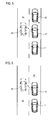
- FIG. 5 A similar situation shows the Fig. 5 , Again, the motor vehicle 1 further follows the motor vehicle 17 as a reference vehicle in the subsequent operating mode. In front of the motor vehicle 17 drives another vehicle 22, thus the next-but-one vehicle to the motor vehicle according to the invention. However, the previously used as a reference vehicle motor vehicle 17 now changes from the lane 16 on the lane 19, see. the indicated position 23. As a result, it falls away as a reference vehicle.
- the speed control system 2 is deactivated by giving an indication to the driver.
- the speed control system 2 can ultimately be used for all speeds.
- Another possibility is to realize on the motor vehicle, possibly also using the environmental sensors 4, a starting monitoring sensor, the data allow the conclusion whether a restart is possible or useful.
- the speed control system 2 in the subsequent operating mode consequently also a stop-and-go function.
- Fig. 6 represents a further traffic situation in which serving as a reference vehicle vehicle 17 leaves the lane 16 and changes to the lane 19, indicated position 23.
- the speed control system can be easily operated again in the normal operating mode with the desired speed, is consequently also changed again.
- the distance control in the subsequent operating mode only refers to the speeds in which the desired speed is undershot. If the desired speed can be driven as the maximum speed, then it is possible to switch back to the normal operating mode, if appropriate with the additional condition that the reference vehicle leaves the sensor detection area altogether. This is another condition under which the subsequent operation mode is deactivated in favor of the normal operation mode (in addition to the illustration in FIG Fig. 6 ).
Landscapes
- Engineering & Computer Science (AREA)
- Automation & Control Theory (AREA)
- Transportation (AREA)
- Mechanical Engineering (AREA)
- Human Computer Interaction (AREA)
- Controls For Constant Speed Travelling (AREA)
- Control Of Driving Devices And Active Controlling Of Vehicle (AREA)
- Electric Propulsion And Braking For Vehicles (AREA)
Applications Claiming Priority (1)
| Application Number | Priority Date | Filing Date | Title |
|---|---|---|---|
| DE102010035086.9A DE102010035086B4 (de) | 2010-08-21 | 2010-08-21 | Verfahren zum Betrieb eines Geschwindigkeitsregelsystems eines Kraftfahrzeugs und Kraftfahrzeug |
Publications (2)
| Publication Number | Publication Date |
|---|---|
| EP2420422A2 true EP2420422A2 (fr) | 2012-02-22 |
| EP2420422A3 EP2420422A3 (fr) | 2016-04-06 |
Family
ID=44677296
Family Applications (1)
| Application Number | Title | Priority Date | Filing Date |
|---|---|---|---|
| EP11006110.8A Withdrawn EP2420422A3 (fr) | 2010-08-21 | 2011-07-26 | Procédé destiné au fonctionnement d'un système de réglage de la vitesse d'un véhicule automobile et véhicule automobile |
Country Status (2)
| Country | Link |
|---|---|
| EP (1) | EP2420422A3 (fr) |
| DE (1) | DE102010035086B4 (fr) |
Families Citing this family (3)
| Publication number | Priority date | Publication date | Assignee | Title |
|---|---|---|---|---|
| DE102012023630B4 (de) | 2012-12-03 | 2025-03-13 | Volkswagen Aktiengesellschaft | Verfahren zur Information eines Fahrzeugführers hinsichtlich eines von einem auf Umgebungsdaten basierten Fahrerassistenzsystems eines Fahrzeugs ausgeführten automatischen Fahrmanövers |
| DE102014208185A1 (de) * | 2014-04-30 | 2015-11-05 | Conti Temic Microelectronic Gmbh | Vorrichtung und Verfahren zur Regelung der Fahrzeuggeschwindigkeit eines Fahhrzeuges durch ein ACC-System |
| EP3819178A1 (fr) * | 2019-11-06 | 2021-05-12 | Visteon Global Technologies, Inc. | Système de commande adaptative de la vitesse pour un véhicule et procédé de commande de la vitesse d'un véhicule |
Family Cites Families (9)
| Publication number | Priority date | Publication date | Assignee | Title |
|---|---|---|---|---|
| DE4112335A1 (de) * | 1991-04-16 | 1992-10-22 | Bosch Gmbh Robert | Einrichtung zur regelung der fahrgeschwindigkeit eines fahrzeugs |
| JP3569926B2 (ja) * | 1993-03-03 | 2004-09-29 | 株式会社デンソー | 車両走行制御装置 |
| DE4437678B4 (de) * | 1994-10-21 | 2007-07-05 | Conti Temic Microelectronic Gmbh | Verfahren zur Abstandsregelung von Kraftfahrzeugen |
| DE19640694A1 (de) * | 1996-10-02 | 1998-04-09 | Bosch Gmbh Robert | Verfahren und Vorrichtung zur Steuerung der Fahrgeschwindigkeit eines Fahrzeugs |
| JP3930110B2 (ja) * | 1997-08-11 | 2007-06-13 | 富士重工業株式会社 | 車両のクルーズコントロール装置 |
| DE10231687A1 (de) * | 2002-07-10 | 2004-01-22 | Robert Bosch Gmbh | Verfahren und Vorrichtung zur Benachtichtigung des Fahrers eines Kraftfahrzeugs |
| DE102005022676A1 (de) * | 2005-05-17 | 2006-11-23 | Robert Bosch Gmbh | Anzeigevorrichtung für einen Geschwindigkeitsregler mit Stop & Go Funktion |
| DE102005057636B4 (de) * | 2005-12-02 | 2022-08-11 | Volkswagen Ag | Kraftfahrzeug |
| JP4913107B2 (ja) * | 2008-09-17 | 2012-04-11 | 日立オートモティブシステムズ株式会社 | 車両速度制御装置および車両速度制御方法 |
-
2010
- 2010-08-21 DE DE102010035086.9A patent/DE102010035086B4/de not_active Expired - Fee Related
-
2011
- 2011-07-26 EP EP11006110.8A patent/EP2420422A3/fr not_active Withdrawn
Non-Patent Citations (1)
| Title |
|---|
| None |
Also Published As
| Publication number | Publication date |
|---|---|
| EP2420422A3 (fr) | 2016-04-06 |
| DE102010035086A1 (de) | 2012-02-23 |
| DE102010035086B4 (de) | 2016-12-01 |
Similar Documents
| Publication | Publication Date | Title |
|---|---|---|
| EP2349805B1 (fr) | Procédé de commande d'un véhicule automobile et dispositif correspondant | |
| EP2944532B1 (fr) | Système d'assistance de feu de circulation pour un véhicule doté d'un dispositif d'affichage | |
| DE102014002111B4 (de) | Verfahren zum Betrieb eines den Fahrer bei einem Ausrollvorgang unterstützenden Fahrerassistenzsystems und Kraftfahrzeug | |
| EP2216197B1 (fr) | Procédé de commande d'un système d'assistance du conducteur et système d'assistance du conducteur | |
| EP1442915B1 (fr) | Régulateur de vitesse avec plusieurs modes de fonctionnement | |
| DE102012002304A1 (de) | Vorrichtung zum automatisierten Führen eines Kraftwagens und Verfahren zum Betreiben eines Kraftwagens | |
| DE102013110852A1 (de) | Verfahren für ein Fahrerassistenzsystem eines Fahrzeugs | |
| DE102018207572B4 (de) | Adaptiver Geschwindigkeitsregler für Kraftfahrzeuge und Verfahren zur adaptiven Geschwindigkeitsregelung | |
| WO2009000580A1 (fr) | Système d'assistance au conducteur avec fonction d'indication de démarrage | |
| WO2001040011A1 (fr) | Regulateur de vitesse pour un vehicule automobile | |
| EP3969342B1 (fr) | Système d'aide à la conduite pour un véhicule à moteur et véhicule à moteur | |
| DE102013205609A1 (de) | Geschwindigkeitssteuerung eines Kraftfahrzeugs | |
| DE102019207327B3 (de) | Fahrerassistenzsystem für ein Kraftfahrzeug und Kraftfahrzeug | |
| EP2028073A1 (fr) | Système d'assistance à la propulsion d'un véhicule avec fonction Stop & Go | |
| WO2023057137A1 (fr) | Procédé de manœuvre d'un véhicule sur une route à plusieurs voies tout en tenant compte d'une pente dans une région d'une sortie de la route, système d'assistance au conducteur et véhicule | |
| EP1575798B1 (fr) | Regulateur de vitesse a plusieurs modes de fonctionnement | |
| EP4267931B1 (fr) | Procédé d'exécution d'un essai de conduite sur au moins un véhicule d'essai | |
| DE102007031543A1 (de) | Verfahren zur Sollabstandsvorgabe bei einer Geschwindigkeitsregelung auf einen vorgegebenen Sollabstand | |
| DE102010035086B4 (de) | Verfahren zum Betrieb eines Geschwindigkeitsregelsystems eines Kraftfahrzeugs und Kraftfahrzeug | |
| EP2280368A1 (fr) | Procédé d'opération d'un véhicule avec control de vitesse comprenant des capteurs de portée proche et lointaine | |
| DE102019126549A1 (de) | Vorrichtung und Verfahren zum Bereitstellen von Informationen für einen Fahrzeuginsassen eines Fahrzeugs | |
| DE102014200284B4 (de) | Verfahren und Vorrichtung zur adaptiven Geschwindigkeitsregelung eines Kraftfahrzeugs mit manuellem Schaltgetriebe | |
| DE102014215673B4 (de) | Fahrerassistenzsystem in einem Kraftfahrzeug | |
| EP3554908B1 (fr) | Procédé pour commander et/ou réguler une chaîne cinématique d'un véhicule automobile | |
| DE102016015150A1 (de) | Verfahren zur Optimierung eines Ausrollvorgangs |
Legal Events
| Date | Code | Title | Description |
|---|---|---|---|
| AK | Designated contracting states |
Kind code of ref document: A2 Designated state(s): AL AT BE BG CH CY CZ DE DK EE ES FI FR GB GR HR HU IE IS IT LI LT LU LV MC MK MT NL NO PL PT RO RS SE SI SK SM TR |
|
| AX | Request for extension of the european patent |
Extension state: BA ME |
|
| PUAI | Public reference made under article 153(3) epc to a published international application that has entered the european phase |
Free format text: ORIGINAL CODE: 0009012 |
|
| PUAL | Search report despatched |
Free format text: ORIGINAL CODE: 0009013 |
|
| AK | Designated contracting states |
Kind code of ref document: A3 Designated state(s): AL AT BE BG CH CY CZ DE DK EE ES FI FR GB GR HR HU IE IS IT LI LT LU LV MC MK MT NL NO PL PT RO RS SE SI SK SM TR |
|
| AX | Request for extension of the european patent |
Extension state: BA ME |
|
| RIC1 | Information provided on ipc code assigned before grant |
Ipc: B60K 37/02 20060101ALI20160301BHEP Ipc: B60W 50/10 20120101ALI20160301BHEP Ipc: B60W 30/14 20060101ALI20160301BHEP Ipc: B60W 30/16 20120101AFI20160301BHEP Ipc: B60W 50/08 20120101ALI20160301BHEP |
|
| 17P | Request for examination filed |
Effective date: 20161006 |
|
| RBV | Designated contracting states (corrected) |
Designated state(s): AL AT BE BG CH CY CZ DE DK EE ES FI FR GB GR HR HU IE IS IT LI LT LU LV MC MK MT NL NO PL PT RO RS SE SI SK SM TR |
|
| STAA | Information on the status of an ep patent application or granted ep patent |
Free format text: STATUS: THE APPLICATION HAS BEEN WITHDRAWN |
|
| 18W | Application withdrawn |
Effective date: 20180712 |