EP2420427B2 - Procédé et dispositif de surveillance de l'état de fonctionnement d'un dispositif d'embrayage - Google Patents
Procédé et dispositif de surveillance de l'état de fonctionnement d'un dispositif d'embrayage Download PDFInfo
- Publication number
- EP2420427B2 EP2420427B2 EP11175827.2A EP11175827A EP2420427B2 EP 2420427 B2 EP2420427 B2 EP 2420427B2 EP 11175827 A EP11175827 A EP 11175827A EP 2420427 B2 EP2420427 B2 EP 2420427B2
- Authority
- EP
- European Patent Office
- Prior art keywords
- train
- signal
- coupling
- uncoupling
- state
- Prior art date
- Legal status (The legal status is an assumption and is not a legal conclusion. Google has not performed a legal analysis and makes no representation as to the accuracy of the status listed.)
- Active
Links
Images



Classifications
-
- B—PERFORMING OPERATIONS; TRANSPORTING
- B61—RAILWAYS
- B61L—GUIDING RAILWAY TRAFFIC; ENSURING THE SAFETY OF RAILWAY TRAFFIC
- B61L15/00—Indicators provided on the vehicle or train for signalling purposes
- B61L15/0018—Communication with or on the vehicle or train
- B61L15/0036—Conductor-based, e.g. using CAN-Bus, train-line or optical fibres
-
- B—PERFORMING OPERATIONS; TRANSPORTING
- B61—RAILWAYS
- B61L—GUIDING RAILWAY TRAFFIC; ENSURING THE SAFETY OF RAILWAY TRAFFIC
- B61L15/00—Indicators provided on the vehicle or train for signalling purposes
- B61L15/0054—Train integrity supervision, e.g. end-of-train [EOT] devices
-
- B—PERFORMING OPERATIONS; TRANSPORTING
- B61—RAILWAYS
- B61L—GUIDING RAILWAY TRAFFIC; ENSURING THE SAFETY OF RAILWAY TRAFFIC
- B61L15/00—Indicators provided on the vehicle or train for signalling purposes
- B61L15/0081—On-board diagnosis or maintenance
Definitions
- the DE 10 2008 034 018B3 discloses a method for determining the coupling state of a UIC coupling, a UIC coupling and an arrangement with a UIC coupling.
- the invention relates to a method for monitoring an operating state of at least one coupling device and/or coupling point of a coupling device provided for the mechanical connection of two vehicles to form a train.
- the invention further relates to an automatic coupling device with a control unit for monitoring an operating state of at least one coupling device and/or coupling point provided for the mechanical connection of two vehicles to form a train.
- the object of the present invention is to provide an improved method and an improved automatic coupling device with a control device which enable reliable detection of an undesired uncoupling in all operating states of a train, in particular also during a standstill or when traveling at very low speed. This object is achieved in the method of the type mentioned at the beginning by the features of claim 1.
- the evaluation according to the invention which takes into account the uncoupling release signal in addition to the coupling state signal, advantageously enables universal monitoring of the coupling device by taking the coupling state signal into account, while at the same time the additional consideration of the uncoupling release signal makes it possible to signal an actually desired uncoupling, so that in the case of a desired uncoupling, error reactions are not also triggered, as may be provided for the detection of an undesired uncoupling.
- the principle according to the invention can be applied to all vehicle combinations or trains that can be formed from individual vehicles by means of at least one coupling device, in particular to rail vehicles with automatic coupling devices.
- the use of the invention is particularly advantageous in vehicles that brake indirectly automatically.
- the coupling state signal is generated by means of a corresponding sensor system that is mounted in the area of the coupling device.
- a limit switch is provided that is mounted on the coupling device in such a way that it carries out a switching state change when the coupling device is transferred from a coupled state to an uncoupled state or vice versa. This electrical switching state change can be evaluated according to the invention.
- sensor means for example capacitive or inductive or optical sensor means, can also be used alternatively or additionally to monitor a clutch state or a state transition.
- the uncoupling release signal is advantageously defined in such a way that it cannot or can only be influenced with difficulty by unauthorized persons, thereby significantly increasing the security of the monitoring method against sabotage.
- a particular advantage of the invention is also that the uncoupling release signal is formed from a combination of several signals or logical links, which in turn are formed from further signals or operating variables, thereby obtaining an even more reliable arrangement.
- the uncoupling release signal is not formed solely as a function of a standstill signal characterizing a speed of the train and/or at least one of the vehicles.
- the uncoupling release signal is generated using the standstill signal, but at least one other signal from the train or vehicle is also evaluated in order to provide increased safety, which also satisfies, among other things, more stringent legal requirements or criteria catalogues from the relevant approval authorities.
- This offers increased evaluation precision compared to known systems in which only the standstill signal is used to decide whether a possible uncoupling process is to be considered permissible or impermissible.
- the invention stands out from such known methods in which it is concluded that any possible uncoupling processes are permissible based solely on the presence of the standstill signal.
- One of the disadvantages of these methods is that, for example, an unauthorized or unwanted uncoupling of vehicles from a train that is ready to depart on the track cannot be detected, since the higher-level evaluation of the standstill signal alone means that any uncoupling is considered permissible when the standstill signal is present.
- the unauthorized operation of a clutch emergency release device on vehicles prepared for departure can also be detected by the method according to the invention, because an effective decoupling release is only indicated by the decoupling release signal according to the invention, which is not only formed as a function of the standstill signal but also of at least one other variable.
- the decoupling release signal according to the invention is not also generated in addition to the detected decoupling (clutch state signal) is present, according to the invention it can advantageously always be concluded that there is undesirable decoupling, in particular while the standstill signal already has a value of logical one, which indicates a standstill condition.
- the uncoupling release signal must be present "simultaneously" with the clutch state signal or a clutch state signal change that indicates uncoupling is understood to mean that the uncoupling release signal must be directly related in time to a change in the state of the clutch state signal that indicates uncoupling.
- the uncoupling release signal must be present first, i.e. before a state of the state clutch signal changes from "coupled” to "uncoupled”, in order not to rule out a vehicle reaction due to undesired uncoupling.
- the uncoupling release signal is essentially the same as the clutch state signal.
- the decoupling release signal can also be activated only shortly after the clutch state signal indicating a decoupling state in order to signal the release, including a desired decoupling.
- the standstill signal which is known per se.
- these signals can be processed or generated in a known manner by logic circuits, e.g. discrete logic circuits made of semiconductor components or relay circuits.
- the uncoupling release signal is generated depending on the standstill signal and a pressure in a main air line of the train. This makes it particularly advantageous to display and distinguish between regular uncoupling and undesired uncoupling. Since the uncoupling release signal in this embodiment depends on the standstill signal, among other things, it is ensured that a desired coupling can only be signaled or recognized when the standstill signal is present, i.e. the train is traveling at a very low speed or is at a standstill.
- the additional criterion of the pressure of the main air line for generating the uncoupling release signal advantageously represents a particularly secure criterion against manipulation, because unauthorized persons generally do not have the option of regulating the pressure in the main air line to a specific value.
- the criterion describing the pressure of the main air line can be designed in such a way that the pressure of the main air line must be reduced from a control pressure (for example 5 bar) to a defined, lower value (for example below 3 bar, e.g. between 2.5 bar and 2.8 bar) so that - with the simultaneous presence of the standstill signal - the uncoupling release signal according to the invention assumes a state of logic 1 (true), thus indicating that a decoupling process that may take place is a desired uncoupling process.
- a control pressure for example 5 bar
- a defined, lower value for example below 3 bar, e.g. between 2.5 bar and 2.8 bar
- the uncoupling release signal is formed as a function of the standstill signal and at least one further signal that characterizes an operating variable of the train and/or at least one vehicle.
- a low-voltage line - analogous to the main air line - also present throughout the train for supplying electrical consumers of the individual vehicles is influenced in a defined manner, for example by modulation with a high-frequency signal which spreads over the entire electrical supply line and can thus be detected in every vehicle of the train by a simple detector circuit. Only when the standstill signal is selected by the control device according to the invention and the modulation signal defined according to the invention is additionally detected on the electrical supply line is it then assumed that a desired uncoupling process is initiated.
- the criterion of the uncoupling release signal according to the invention can also include other signals which can also be implemented, for example, by means of RFID identification transmitters and corresponding receivers in the area of the train.
- the control device can, for example, check whether the standstill signal is present and whether a specific, authorized RFID identification transmitter has been connected to the train's reading electronics at the same time in order to indicate authorized uncoupling. In all other cases, a vehicle reaction can be triggered because it has been concluded that uncoupling has occurred undesirably.
- the uncoupling release signal is formed as a function of at least two operating variables of the train and/or at least one vehicle, in particular as a function of a) a signal from an input device that can be operated by an operator and b) a pressure in a main air line of the train.
- the standstill signal is therefore not used to form the uncoupling release signal according to the invention.
- the signal from an input device that can be operated by an operator can be, for example, an output signal from a key switch, which can also be integrated into an existing system of the vehicle, such as a driver's console or a control cabinet.
- the input device can also be designed as a conventional switch (without a key) or as another input system, e.g. as an RFID input system or the like.
- the second criterion used is again the air pressure in a main air line of the train or vehicle, which can be evaluated, for example, by means of a pressure switch in a manner known to those skilled in the art and can be linked to the signal of the switch in order to form the uncoupling release signal according to the invention.
- the coupling state signals of several coupling devices are evaluated by the control device.
- the control device In a train composed of several, for example three, vehicles, it is particularly advantageous for all three coupling devices of the corresponding vehicles to be monitored according to the invention, but at least the two coupling devices that connect the first and second vehicles and the second and third vehicles to one another.
- a clutch state signal of a single clutch point of a clutch device is evaluated by the control device.
- an automatic coupling device with a control device according to claim 8 is provided.
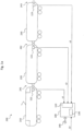
- Figure 1 shows a train 200, which is composed of a total of three rail vehicles 210, 220, 230.
- the first vehicle 210 is a traction vehicle, e.g. a locomotive.
- two coupling devices 247, 242 are provided, which connect the vehicles 210, 220, 230 to one another in a manner known per se.
- the coupling device 243 on the in Figure 1 right end of the vehicle 230 is not coupled with another counterpart of another vehicle, since the vehicle 230 is the last car (end car) of the train 200 according to Figure 1 forms.
- the coupling devices 241, 242, 243 3 can be automatic couplings which, in a manner known per se, also realize an electrical and/or pneumatic connection of the individual train parts 210, 220, 230 to one another in addition to a purely mechanical connection.
- sensor means 121, 122, 123 are provided which detect a coupling state of the respective coupling device 241, 242, 243.
- the sensor means 121, 122, 123 are designed as limit switches, i.e. as electromechanical sensor means, which experience an electrical state change when the operating state of the respective coupling device 241, 242, 243 changes from "uncoupled” to “coupled” or vice versa.
- the limit switches 121, 122, 123 can also be integrated directly into the coupling devices 241, 242, 243, for example.
- a control device 100 which has an input interface 110 for receiving the coupling state signals S1, S2, S3, as supplied by the limit switches 121, 122, 123.
- the coupling state signals S1, S2, S3 are evaluated by the control device 100 in order to conclude that decoupling is desired or that decoupling is undesirable.
- control device 100 has a control unit 130 which is at least partially designed in one of the following technologies: discrete logic circuit using semiconductor components (e.g. CMOS circuits), relay circuit, microcontroller, digital signal processor, programmable logic component, application-specific integrated circuit.
- semiconductor components e.g. CMOS circuits
- relay circuit e.g., relay circuit
- microcontroller e.g., microcontroller
- digital signal processor e.g., digital signal processor, programmable logic component, application-specific integrated circuit.
- the control device 100 concludes that a vehicle 220 is being uncoupled if the coupling state signal S2 of the relevant coupling device 242 indicates an uncoupled state or a transition to this state and a decoupling release signal EF does not simultaneously indicate the presence of an actually desired decoupling process.
- the decoupling release signal EF provided according to the invention must indicate the presence of an actually desired decoupling process.
- a desired decoupling process must be signaled by means of a separate decoupling release signal EF.
- the decoupling release signal EF is preferably also fed to the control device 100 and also evaluated by this or its control unit 130.
- the uncoupling release signal EF is formed as a function of at least two different variables, in particular of different operating variables of the train 200 or individual vehicles 210, 220, 230.
- the uncoupling release signal EF is thus not only formed as a function of, for example, a standstill signal STS ( Figure 2a ) is formed.
- a standstill signal STS Figure 2a
- conventional methods in which only the standstill signal STS is evaluated, and in which, when the standstill signal STS indicates that the train 200 is at a standstill, no consideration is given to any signals that may be present that indicate a coupling state, there is a disadvantage in that there is no possibility of monitoring an undesired uncoupling when the train is at a standstill.
- the decoupling release signal EF is dependent on the standstill signal STS ( Figure 2a ) and the pressure PHLL in the main air line (not shown) of train 200 ( Figure 1 ).
- the main air line is a pneumatic system that runs through the entire train 200.
- a standard operating pressure for the main air line is usually 5 bar.
- the main air line is usually used to operate a safety braking system of the train 200.
- the brakes of the train 200 are released.
- the pressure PHLL is reduced - starting from the standard operating pressure - until the desired braking effect is achieved.
- the brakes are released again by increasing the pressure PHLL in the main air line up to the standard operating pressure.
- the inventive formation of the decoupling release signal EF depending on the standstill signal STS and the pressure PHLL in the main air line of the train 200 advantageously enables the creation of a particularly reliable criterion for displaying an actually desired uncoupling process.
- the uncoupling release signal EF according to the above definition is only present or only has a value of "logical one" (true) if, firstly, the standstill signal STS is also "logical one", i.e. the train 200 is either moving very slowly or is standing still, and secondly, if the defined pressure PHLL is present in the main air line of the train 200.
- This defined pressure is a specially predeterminable pressure or pressure range of or around, for example, 2.8 bar, which thus means a code to display the information that a desired uncoupling process is to take place.
- the targeted setting of this special pressure value or pressure range in the main air line is generally impossible for unauthorized persons and can usually only be initiated from a driver's console on train 200. This ensures that no unwanted manipulation by unauthorized persons or malfunctions lead to an uncoupling release signal EF being incorrectly signaled with the value "logical one".
- a valid uncoupling release signal EF can only be generated if the standstill signal STS is actually present or has a value of logical one, and if the predetermined pressure PHLL of the main air line has been initiated by deliberate action by the train driver or another authorized person. This means that in order to indicate an actually desired coupling process, the train 200 must first be transferred to an operating state in which the standstill signal STS has a value of logical 1, and furthermore the pressure PHLL in the main air line must be reduced or set to the predefined value.
- the initiation of the vehicle reaction by the control unit 100 can, for example, take place via an interface 140 to a driver's console and/or a vehicle bus and/or a control center.
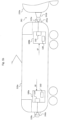
- Figure 1b shows a traction vehicle 210a according to a further, particularly preferred, embodiment of the invention.
- the traction vehicle 210a has on its Figure 1b left front side has a first coupling point 240a, which is currently not connected to a suitable coupling point of another vehicle (not shown).
- the traction vehicle 210a has on its Figure 1b right front side has a second coupling point 241a, which is connected to the matching coupling point 241b of another vehicle 220a.
- the second coupling point 241a forms with the coupling point 241b of the other vehicle 220a a coupling device 241 comparable to the system according to Figure 1a .
- the traction vehicle 210a has a total of two control units 100a, 100b, the functionality and structure of which essentially correspond to that of the control unit 100 from Figure 1a
- the first control unit 100a is assigned to the first coupling point 240a
- the second control unit 100b is assigned to the second coupling point 241a.
- the first coupling point 240a is also assigned the sensor means 120a (again, e.g. limit switches), which generate a coupling state signal or coupling point state signal characterizing the operating state of the coupling point 240a and feed it to the control unit 100a.
- the control unit 100b receives a comparable coupling state signal or coupling point state signal characterizing the operating state of the coupling point 241a from the sensor means 121a, which are also arranged in the area of their assigned coupling point 241a or are integrated therein.
- Each control unit 100a, 100b operates autonomously, i.e. independently of other similar control units 100b, 100a of the traction vehicle and is designed to execute of the method according to the invention.
- the control unit 100a, 100b according to Figure 1b a "single-channel" system compared to the variant according to Figure 1a , because the control unit 100a, 100b only monitors one coupling point 240a, 241a assigned to it.
- This "single-channel" variant is particularly preferred because it does not require any vehicle-wide signal connections, as may be the case with the system according to Figure 1a is the case.
- Figure 1b shows a traction vehicle 210a which has two independent monitoring systems according to the invention for a coupling state, wherein the components 100a, 120a form the first system, and wherein the components 100b, 121a form the second system.
- the coupling device 241 comprising both interacting coupling points 241a, 241b would advantageously be monitored simultaneously by two systems according to the invention, namely one for each coupling point 241a, 241b.
- train 200 would be Figure 1a - instead of the "three-channel" system shown - have a maximum of six monitoring systems in total, namely five for the Figure 1a illustrated coupling points of the coupling devices 241, 242, 243 and a sixth system for the Figure 1a second coupling point of traction vehicle 210 (not shown).
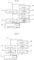
- Figure 2a shows a first logic diagram for forming the decoupling release signal EF according to the invention in accordance with a first embodiment.
- a first input variable is formed by the standstill signal STS, which is present in the train 200 in a manner known per se only when the train 200 has a speed that is less than or equal to a predeterminable threshold of, for example, approximately 1 or 2 km/h.
- the second input signal represents a pressure PHLL in a main air line of the train 200.
- the evaluation block 180 it is checked whether the standstill signal STS has a value of logical one, and whether at the same time the pressure PHLL in the main air line is in a predeterminable pressure range (for example between approximately 2.5 bar and approximately 2.8 bar) or pressure value.
- the evaluation block 180 outputs the decoupling release signal EF according to the invention with a value of logical one at its output 181 in order to inform the control device 100 ( Figure 1 ) to indicate that a desired uncoupling process is imminent. If one of the two criteria for the input variables STS, PHLL is not met, the output variable EF has a value of logical zero, so that the control device 100 triggers a corresponding vehicle reaction when uncoupling in the area of the coupling devices 241, 242 is detected by the signals S1, S2.
- the functionality of the evaluation block 180 is preferably implemented in the control unit 130 of the control device 100. The same applies to the evaluation block 182 described below.
- Figure 2b shows a further embodiment for determining the decoupling release signal EF according to the invention.
- the standstill signal STS is again fed to the input of the evaluation device 182.
- a modulation signal Mod is provided as a second input variable for the evaluation block 182.
- the modulation signal Mod is a signal that can be triggered, for example, by an authorized person in the area of one of the vehicles 210, 220, 230 and/or the corresponding coupling device 241, 242, 243, for example by modulating a corresponding supply voltage of an electrical supply line running through the entire train 200 (not shown). Similar signaling can also be carried out by means of a known RFID transponder system or the like.
- Wireless signaling of the modulation signal Mod directly to the control device 100 is also conceivable, for example by means of a short-range radio connection (WLAN, Bluetooth, ZigBee) or the like.
- WLAN wireless local area network
- Bluetooth ZigBee
- Cellular communication networks GSM, UMTS, LTE
- GSM Global System for Mobile communications
- a decoupling release signal EF with a truth value of logical one is only output at an output 183 of the evaluation block 182 if the standstill signal STS has a value of logical one, thus the standstill condition is fulfilled, and if at the same time the modulation signal Mod indicates that an authorized person is signaling a desired impending decoupling process.
- This can be done, for example, using a predefinable modulation scheme.
- the control device 100 concludes, by evaluating the signal EF of the evaluation unit 182, that a desired decoupling process is taking place and does not trigger any vehicle reactions as are provided for in the event of an undesired decoupling process.
- the uncoupling release signal EF depends on at least two operating variables of the train 200 ( Figure 1a ) and/or at least one vehicle 210, in particular depending on a) a signal from an input device operable by an operator and b) a pressure PHLL in a main air line of the train 200.
- the standstill signal STS is therefore not necessarily used to form the decoupling release signal EF according to the invention.
- the signal from an input device that can be operated by an operator can be, for example, an output signal from a key switch 502a ( Figure 5 ) which can also be integrated into an existing system of the vehicle 210, such as a driver's console or a control cabinet.
- the input device can also be designed as a conventional switch (without a key) or as another input system 502a, e.g. as an RFID input system or the like.
- the second criterion used is again the air pressure PHLL in a main air line of the train 200 or vehicle 210, which is shown in the flow chart according to Figure 5 for example, by means of the pressure switch 502b in a manner known to those skilled in the art, it is determined and evaluated and can be linked to the signal of the switch 502a in order to form the decoupling release signal EF according to the invention, which is present at the output of the evaluation block 502 for forwarding to the evaluation block 504, which in turn is implemented, for example, in the control device 100, e.g. as a logic circuit in the control unit 130.
- the function block 506 which is subordinate to the evaluation block 504, serves to control the decoupling valves 506b, for example in those operating cases in which the previous evaluation of the relevant clutch status signal s1 and the decoupling release signal EF has shown that a desired decoupling should be carried out. Then, according to Figure 5 Block 506a checks whether the standstill signal STS is present, and if this is the case, two control branches 506b for redundant decoupling valves 1, 2 are activated to carry out the decoupling.
- the standstill signal STS is therefore not used to form the uncoupling release signal EF, but the standstill condition is only checked by block 506a when the uncoupling is to take place.
- the standstill condition STS could also be checked directly in the evaluation block 502, ie in addition to the two other criteria 502a, 502b.
- Figure 3 shows a flow chart of an embodiment of a method according to the invention.
- a first step 300 the clutch state signals S1, S2, S3 ( Figure 1 ) is evaluated.
- the second step 310 the presence of the decoupling release signal EF according to the invention is checked, for example by means of the method described above with reference to the Figures 2a, 2b described logic circuits.
- step 320 an evaluation is carried out as to whether, when a clutch state change is detected, at least one of the clutch state signals S1, S2, S3 simultaneously has the decoupling release signal EF present, and if necessary, a corresponding vehicle reaction is initiated.
- the procedure according to Figure 3 can preferably run permanently during operation of the train 200 or only in predeterminable operating situations or times.
- An appropriate supply of electrical energy to the control device 100 and the supply of the signals S1, S2, S3, STS, PHLL, Mod must be ensured for the desired operating cases.
- the supply of the signals S1, S2, S3, STS, PHLL, Mod can either take place via separate channels or lines, or at least partially via the interface 140 to other on-board systems of the train 200.
- the control device 100a is accordingly to be supplied with the sensor signal indicating a coupling point state, e.g. from the sensor 120a, as well as with the signal EF, which is formed, e.g., by an external logic integrated into an existing control cabinet of the vehicle 210.
- a logic like the control device 100a, can also be integrated directly into a driver's console or a control panel supplementing the driver's console.
- the logic 502 forming the signal EF ( Figure 5 ) must be connected to the required input signals 502a, 502b and if necessary 506a or STS ( Figure 2a ) are supplied.
- FIG 4a shows a logic diagram of a further embodiment of the invention, which explains the monitoring of a coupling device 241 according to the invention.
- the connection 401 corresponds to a vehicle voltage connection of the train 200.
- the subordinate function block 408 it is checked whether the standstill signal STS ( Figure 2a, 2b ) is active, thus indicating that the train 200 is at a standstill. If this is the case, the system branches to the subordinate block 410, where it is checked whether a driver's console of the train 200 or the railcar 210 ( Figure 1 ) has been activated for a defined time interval. If this is the case, a branch is made to function block 404, which checks whether the coupling device 241 is mechanically coupled.
- function block 404 corresponds to a check or evaluation of the coupling state signal S1 by the control unit 100. If the criterion of function block 404 is also met, a branch is made to function block 406, in which a "no train break" flag is signaled or set for the coupling device 241.
- the function blocks 408, 410, 404 explained above correspond to an initialization path as it is run through during initialization after the control device 100 according to the invention is switched on. The "no train break" flag indicates that no undesired uncoupling has been detected since then within the scope of the inventive monitoring of the operating state of the coupling device 241.
- function block 402 checks whether there is no break in the coupling device 241. If this is the case, the system branches to function block 404 and finally to 406.
- the other function blocks 412, 414 check whether the standstill signal is active and then whether a defined main line pressure for uncoupling is present (block 414).
- the function blocks 412, 414 correspond to a function branch that is run through when an authorized person takes all measures to prepare for a desired uncoupling, namely to signal the uncoupling release signal EF.
- the function blocks 412, 414 check the criteria (STS, PHLL) required for the output of the uncoupling release signal EF with a value of logical one and then branch again to the function block 406, which sets the status flag "no train break" of the coupling device 241.
- a comparable logic structure can be provided for the further coupling devices 242, 243 of the train 200 and the control device 100.
- Figure 4b gives a block diagram that describes a detection of the end car 230.
- An initialization branch is given by the function blocks 422, 424, whereby the function block 422, which checks whether the car 230 is not coupled, is in turn connected to a vehicle voltage or a vehicle voltage connection 421. If the car 230 is not coupled, i.e. its coupling device 243 is not connected to a corresponding coupling device of another, following car (not shown), a check is made in the function block 424 as to whether the driver's console has been activated for a defined time interval. If this is not the case, a branch is made to block 426, in which it is concluded that the car 230 is not coupled, and therefore represents an end car 230.
- the branch formed by the function blocks 428, 430, 432 successively checks whether the standstill signal STS ( Figure 2a, 2b ) is active (block 428), whether the driver's console is activated for a defined time interval (block 430), and whether the car 230 is mechanically coupled (block 432). Only when these criteria are met does the system branch to block 426.
- the two branches according to Figure 4b are equally used to determine whether the car 230 is an end car, compare block 426.
- Figure 4c shows a logic diagram which illustrates the signal flow as it is used in a further embodiment to set the "no train break" flag.
- this flag is preferably always set after an initialization of the control device 100 when all limit switches of the sensor means 121, 122, 123 have been checked and no uncoupled state has been detected.
- the flag is preferably stored over the entire operating period of the control device 100.
- connection 441 is in turn connected to a vehicle voltage connection of the train 200.
- block 442 it is determined whether a carriage is not coupled, which corresponds, for example, to the evaluation of the limit switch 121 by the control device 100.
- the flag "no train break" is set.
- a safety loop is closed in blocks 448 or no emergency brake is set, so that no safety braking is triggered.
- the train end signals are controlled in a predefined manner.
- the block 450 is in turn connected to a vehicle voltage connection 441'.
- function block 442 it is also possible to branch to block 444 via the function block 446, which checks whether there is no train break at a coupling point, in which the flag "no train break" is set.
- Function block 442 is successfully completed if the logic structure defined by Figure 4c The checked car is an end car 230, while the function block 446 according to Figure 4c is successfully completed if the checked car is not the end car 230 and at the same time there is no train break at the coupling device 241.
- the logic structures according to the above with reference to the Figures 4a, 4b , 4c are advantageously also implemented in the control device 100, in particular in the control unit 130. They can preferably be implemented as relay circuits or in the form of a program for a microcontroller and/or a digital signal processor (DSP).
- DSP digital signal processor
- EPGA programmable logic components
- CPLD CPLD
- ASIC application-specific integrated circuits
- the embodiments described above advantageously make it possible to detect an unwanted train separation, which is also possible regardless of speed, especially when the train is at a standstill. Reliable detection can also be carried out for different configurations of the train 200.
- the following operating states are covered: normal operation (with existing control technology), restricted operation (control via train control lines without control technology), towing operation with active vehicle parts.
- the coupling states "mechanically coupled” or “mechanically not coupled” are automatically detected by means of the coupling state signals S1, S2, S3 and the sensor means 121, 122, 123 (for example limit switches), and a Flag "no train break" is set or initialized.
- the flag can be implemented, for example, in a hard-wired circuit by a relay. If a coupling state changes at the uncoupled coupling point 243 of the end car 230, this has no influence on the train break detection according to the invention according to a preferred embodiment.
- the signalling of an intentional train separation is advantageously carried out using the dedicated uncoupling release signal EF, which in turn can depend on various criteria (STS, PHLL, MOD).
- the following technical implementation is achieved in detail: if a driver's console is activated in the train 200/train formation, for example in a power car 210, then the status of each coupling device 241, 242, 243 in the train formation 200 is queried over a short time interval and stored in the control device 100, for example using the "no train break" flag. The monitoring according to the invention remains active until a driver's console is activated again.
- the state of a coupling device 241, 242 changes from “coupled” to "uncoupled” due to an unintentional train separation/unintentional uncoupling
- the "no train break" flag is deleted via the control device 100 and one or more of the vehicle reactions described several times above are triggered.
- the vehicle reactions can, for example, be the interruption of a safety/emergency braking loop in the still leading train part 210 and in the separated train part 220, 230.
- the other vehicle reactions, which are preferably also carried out, are described above.
- the current requirements for the vehicle reaction of train 200 can also be met, particularly in the event of an unintentional train separation, as set out in the supplementary regulations no. B015 "Protection goals derived from Section 4 AEG and EBO for coupling vehicles with automatic coupling when stationary" (Internet: WWW.EBA.BUND.DE Home page > Infothek > Vehicles > Brakes).
- the decoupling release signal EF is generated as follows: in order to signal a regular decoupling by means of the decoupling release signal EF according to the invention, the main air line is lowered from a control pressure to a defined value of, for example, 2.8 bar, and with the additional presence of the standstill signal STS, a decoupling process (for example with a key switch or decoupling cable) can be carried out without this being detected as a train break, because the control device 100 has been successfully informed via the decoupling release signal EF according to the invention that a desired decoupling process will be carried out.
- a decoupling process for example with a key switch or decoupling cable
- the circuit or control device 100 can only be reset by deactivating and reactivating a driver's console (if necessary combined with a renewed confirmation of the now changed train configuration) in the train 200/train section.
- the control device 100 is preferably equipped with the communication interface 140 for communication with the driver's console of the railcar 210 or another vehicle, but can also have further or several interfaces to other systems.
- the darkening of the end-of-train signals can only be cancelled by the train driver/conductor operating a special control element, but the "train break" event must first be acknowledged by the train driver, for example by making a corresponding entry in a human-machine interface provided for this purpose on the control device 100, such as a key switch or a graphical user interface.
- a human-machine interface provided for this purpose on the control device 100, such as a key switch or a graphical user interface.
Landscapes
- Engineering & Computer Science (AREA)
- Mechanical Engineering (AREA)
- Health & Medical Sciences (AREA)
- Biomedical Technology (AREA)
- General Health & Medical Sciences (AREA)
- Electric Propulsion And Braking For Vehicles (AREA)
- Arrangement And Mounting Of Devices That Control Transmission Of Motive Force (AREA)
- Train Traffic Observation, Control, And Security (AREA)
Claims (12)
- Procédé de surveillance de l'état de fonctionnement d'au moins un dispositif de couplage automatique (241, 242, 243) conçu pour la liaison mécanique de deux véhicules (210, 220) pour former un train (200), un interrupteur de fin de course étant monté sur le dispositif de couplage automatique (241, 242, 243), l'interrupteur de fin de course étant monté sur le dispositif de couplage (241, 242, 243) de manière à effectuer un changement d'état de commutation électrique lorsque le dispositif de couplage (241, 242, 243) passe d'un état accouplé à un état désaccouplé ou inversement,
dans lequel un signal d'état de couplage (s1, s2, s3), caractérisant un état de fonctionnement du dispositif de couplage (241, 242, 243), est généré au moyen de l'interrupteur de fin de course et analysé par un dispositif de commande (100), un découplage indésirable d'un véhicule (220) étant déterminé lorsque le signal d'état de couplage (s1, s2, s3) affiche un état désaccouplé et si un signal d'autorisation de découplage (EF) n'affiche pas en même temps l'existence d'un processus de découplage souhaité, le signal d'autorisation de découplage (EF) étant généré non pas uniquement en fonction d'un signal d'immobilisation (STS) caractérisant une vitesse du train (200) et/ou d'au moins un des véhicules (210, 220), mais également en fonction d'au moins un autre signal, qui caractérise une grandeur de fonctionnement du train (200) et/ou d'au moins un véhicule (210, 220, 230), l'autre signal étant une pression (PHLL) dans une conduite d'air principale du train (200) ou un signal de modulation obtenu par modulation d'une tension d'alimentation d'une ligne électrique d'alimentation traversant l'ensemble du train. - Procédé selon la revendication 1, caractérisé en ce que le signal d'autorisation de découplage (EF) est généré en fonction d'au moins deux grandeurs de fonctionnement du train (200) et/ou d'au moins un véhicule (210, 220, 230), plus particulièrement en fonction a) d'un signal d'un dispositif d'entrée pouvant être actionné par un opérateur et b) d'une pression (PHLL) dans une conduite d'air principale du train (200).
- Procédé selon l'une des revendications précédentes, caractérisé en ce qu'une réaction de véhicule est déclenchée lorsqu'un découplage indésirable a été détecté.
- Procédé selon la revendication 3, caractérisé en ce que la réaction du véhicule comprend au moins une des étapes suivantes :- interruption d'une boucle de freinage de sécurité / rapide dans une partie du train encore entraînante et/ou dans la partie du train séparée,- désactivation d'un signal lumineux de fin de train au niveau de l'ancien point de couplage, plus particulièrement selon Ril 408 DB Netz AG,- déclenchement de messages de systèmes de contrôle correspondants, plus particulièrement dans un mode de fonctionnement normal,- suppression de la configuration confirmée du train, plus particulièrement dans tous les modes de fonctionnement,- mise en place d'un verrouillage de traction matériel sur la base de l'état de couplage désormais différent dans chaque partie du train.
- Procédé selon l'une des revendications précédentes, caractérisé en ce que les signaux d'état de couplage (s1, s2, s3) de plusieurs dispositifs de couplage (241, 242, 243) sont analysés par le dispositif de commande (100).
- Procédé selon l'une des revendications 1 à 4, caractérisé en ce qu'un signal d'état de couplage d'un seul point de couplage (241a) d'un dispositif de couplage (241) est analysé par le dispositif de couplage (100b).
- Dispositif de couplage automatique (241) pour un véhicule (210, 220, 230 ; 210a, 220a), plus particulièrement un véhicule ferroviaire, un interrupteur de fin de course étant monté sur le dispositif de couplage automatique (241), avec un dispositif de commande (100a, 100b, 100) pour la surveillance d'un état de fonctionnement du dispositif de couplage (241, 242, 243) conçu pour la liaison mécanique de deux véhicules (210, 220) en un train (200), dans lequel un signal d'état de couplage (s1, s2, s3) caractérisant un état de fonctionnement du dispositif de couplage (241, 242, 243) peut être généré au moyen de l'interrupteur de fin de course et analysé par le dispositif de commande (100), l'interrupteur de fin de course étant monté sur le dispositif de couplage (241, 242, 243) de manière à effectuer un changement d'état de commutation électrique lorsque le dispositif de couplage (241, 242, 243) passe d'un état accouplé à un état désaccouplé ou inversement, le dispositif de commande (100) étant conçu de façon à déterminer un découplage indésirable d'un véhicule (220) lorsque le signal d'état de couplage (s1, s2, s3) affiche un état découplé et si un signal d'autorisation de découplage (EF) n'affiche pas en même temps l'existence d'un processus de découplage souhaité, et le dispositif de commande (100a, 100b, 100) comprenant un bloc d'analyse (180, 182) qui est conçu de façon à ce que le signal d'autorisation de découplage (EF) soit généré non pas uniquement en fonction d'un signal d'immobilisation (STS) caractérisant une vitesse du train (200) et/ou d'au moins un des véhicules (210, 220), mais également en fonction d'au moins autre signal, qui caractérise une grandeur de fonctionnement du train (200) et/ou d'au moins un véhicule (210, 220, 230),
dans lequel l'autre signal est une pression (PHLL) dans une conduite d'air principale du train (200) ou un signal de modulation obtenu par modulation d'une tension d'alimentation d'une ligne électrique d'alimentation traversant l'ensemble du train. - Dispositif de couplage selon la revendication 7, le dispositif de commande étant caractérisé par une unité de commande (130) qui est réalisée au moins partiellement à l'aide d'une des technologies suivantes : circuit à relais, micro-contrôleur, processeur numérique de signaux, composant à logique programmable, circuit intégré spécifique à l'application.
- Dispositif de couplage selon l'une des revendications 7 à 8, le dispositif de commande étant caractérisé par au moins une interface (140) pour la communication avec un autre système du train (200) et/ou d'au moins un véhicule (210, 220, 230).
- Dispositif de couplage selon l'une des revendications 7 à 9, le dispositif de commande (100) étant conçu pour l'exécution du procédé selon l'une des revendications 1 à 6.
- Dispositif de couplage selon l'une des revendications 7 à 10, le dispositif de commande (100) étant conçu pour exécuter et/ou déclencher une réaction du véhicule avec au moins une des étapes suivantes :- interruption d'une boucle de freinage de sécurité / rapide dans une partie du train encore entraînante et/ou dans la partie du train séparée,- désactivation d'un signal lumineux de fin de train au niveau de l'ancien point de couplage, plus particulièrement selon Ril 408 DB Netz AG,- déclenchement de messages lumineux correspondants, plus particulièrement dans un mode de fonctionnement normal,- suppression de la configuration confirmée du train, plus particulièrement dans tous les modes de fonctionnement,- mise en place d'un verrouillage de traction matériel sur la base de l'état de couplage désormais différent dans chaque partie du train.
- Véhicule (210, 210a), plus particulièrement véhicule ferroviaire, avec au moins un dispositif de couplage (241) selon l'une des revendications 7 à 11.
Priority Applications (1)
| Application Number | Priority Date | Filing Date | Title |
|---|---|---|---|
| PL11175827T PL2420427T3 (pl) | 2010-08-16 | 2011-07-28 | Sposób i urządzenie do kontroli stanu roboczego urządzenia sprzęgowego |
Applications Claiming Priority (1)
| Application Number | Priority Date | Filing Date | Title |
|---|---|---|---|
| DE201010035302 DE102010035302C5 (de) | 2010-08-16 | 2010-08-16 | Verfahren und Vorrichtung zur Überwachung eines Betriebszustands einer Kupplungsvorrichtung |
Publications (4)
| Publication Number | Publication Date |
|---|---|
| EP2420427A2 EP2420427A2 (fr) | 2012-02-22 |
| EP2420427A3 EP2420427A3 (fr) | 2015-04-15 |
| EP2420427B1 EP2420427B1 (fr) | 2017-08-30 |
| EP2420427B2 true EP2420427B2 (fr) | 2025-01-08 |
Family
ID=44543068
Family Applications (1)
| Application Number | Title | Priority Date | Filing Date |
|---|---|---|---|
| EP11175827.2A Active EP2420427B2 (fr) | 2010-08-16 | 2011-07-28 | Procédé et dispositif de surveillance de l'état de fonctionnement d'un dispositif d'embrayage |
Country Status (4)
| Country | Link |
|---|---|
| EP (1) | EP2420427B2 (fr) |
| DE (1) | DE102010035302C5 (fr) |
| PL (1) | PL2420427T3 (fr) |
| RU (1) | RU2563095C2 (fr) |
Families Citing this family (20)
| Publication number | Priority date | Publication date | Assignee | Title |
|---|---|---|---|---|
| DE102012009114B4 (de) * | 2012-05-09 | 2014-03-13 | Db Fernverkehr Ag | Verfahren zum Kuppeln von Schienenfahrzeugen |
| FR2996705B1 (fr) * | 2012-10-10 | 2014-12-12 | Ms Relais | Panneau a relais configurable |
| US8942868B2 (en) * | 2012-12-31 | 2015-01-27 | Thales Canada Inc | Train end and train integrity circuit for train control system |
| EP3000688A1 (fr) * | 2014-09-26 | 2016-03-30 | Siemens Rail Automation S.A.U. | Système et procédé pour vérifier l'intégrité d'un véhicule à unités multiples |
| CN105059310B (zh) * | 2015-08-10 | 2017-10-03 | 中车青岛四方机车车辆股份有限公司 | 一种实现头尾车任意重联的控制系统及控制方法 |
| NL2018143B1 (en) * | 2017-01-09 | 2018-07-25 | Jtag Tech B V | A system and method of testing correct mechanical coupling of vehicles forming a train. |
| RU2679850C2 (ru) * | 2017-01-30 | 2019-02-13 | Общество с ограниченной ответственностью (ООО) "ПРЕМИКС" | Способ обучения эвакуации машин |
| CN107097809B (zh) * | 2017-03-31 | 2019-02-01 | 中车青岛四方机车车辆股份有限公司 | 司机室监控的控制方法以及司机室监控的控制装置 |
| CN109808617B (zh) * | 2017-11-21 | 2022-03-18 | 中车唐山机车车辆有限公司 | 一种列车和列车供电控制方法 |
| CN108163012B (zh) * | 2017-12-27 | 2019-12-03 | 卡斯柯信号有限公司 | 一种支持列车动态连挂和解编的控制方法 |
| RU2689089C1 (ru) * | 2018-07-09 | 2019-05-23 | Федеральное государственное бюджетное образовательное учреждение высшего образования Иркутский государственный университет путей сообщения (ФГБОУ ВО ИрГУПС) | Способ контроля технического состояния автосцепки вагона при текущем осмотре |
| CN111824184B (zh) * | 2020-06-30 | 2021-12-17 | 通号城市轨道交通技术有限公司 | 连挂列车的解编方法及系统 |
| CN111994097B (zh) * | 2020-08-19 | 2021-11-12 | 交控科技股份有限公司 | 一种基于协同编队的y字型线路动态解编方法及系统 |
| DE102021132991A1 (de) | 2020-12-15 | 2022-06-15 | Voith Patent Gmbh | Automatische Zugkupplung und Verfahren zum Entkuppeln einer automatischen Zugkupplung |
| EP4504573B1 (fr) * | 2022-04-06 | 2026-01-21 | Voith Patent GmbH | Système de dételage, attelage automatique simple traction, véhicule ferroviaire doté d'un attelage automatique simple traction pourvu d'un système de dételage de ce type, et procédé de dételage d'un attelage automatique qui est attelé mécaniquement à un attelage simple traction homologue |
| DE102022204795A1 (de) * | 2022-05-16 | 2023-11-16 | Siemens Mobility GmbH | Verfahren und System zur automatisierten Ermittlung der Zugintegrität eines Zugverbands |
| DE102022212063A1 (de) * | 2022-11-14 | 2024-05-16 | Knorr-Bremse Systeme für Schienenfahrzeuge GmbH | Sichere Entkupplung von Schienenfahrzeugen |
| DE102023119384A1 (de) * | 2023-07-21 | 2025-01-23 | Voith Patent Gmbh | Kupplungssteuerungssystem zur Steuerung von Kupplungen zwischen spurgebundenen Fahrzeugen sowie Verfahren zum Betreiben eines solchen Systems |
| DE102023126615A1 (de) * | 2023-09-29 | 2025-04-03 | Voith Patent Gmbh | Entkuppelsystem, automatische Zugkupplung und Schienenfahrzeug mit einer automatischen Zugkupplung mit einem derartigen Entkuppelsystem und Verfahren zum Entkuppeln einer mechanisch mit einer Gegen-Zugkupplung gekoppelten automatischen Kupplung |
| DE102024123760A1 (de) * | 2024-08-20 | 2026-02-26 | Kb Intellectual Property Gmbh & Co. Kg | Schaltvorrichtung für eine Schienenfahrzeugeinheit zur Ansteuerung eines Kupplungsvorgangs sowie Schienenfahrzeugeinheit und Schienenfahrzeugverband |
Citations (1)
| Publication number | Priority date | Publication date | Assignee | Title |
|---|---|---|---|---|
| US20100148013A1 (en) † | 2005-12-23 | 2010-06-17 | General Electric Company | System and method for optical locomotive decoupling detection |
Family Cites Families (6)
| Publication number | Priority date | Publication date | Assignee | Title |
|---|---|---|---|---|
| RU2272249C2 (ru) * | 2004-02-24 | 2006-03-20 | Общество с ограниченной ответственностью "Научно-производственное предприятие "СПЕКТР" | Устройство автоматического контроля механизма автосцепных устройств грузовых вагонов от саморасцепа на ходу поезда |
| US7845504B2 (en) * | 2005-12-23 | 2010-12-07 | General Electric Company | System and method for determining whether a locomotive or rail engine is coupled to a rail car or other engine |
| DE102006005207B4 (de) * | 2006-02-02 | 2007-10-18 | Deutsches Zentrum für Luft- und Raumfahrt e.V. | Vorrichtung zur fahrzeugseitigen Überwachung der Zugvollständigkeit |
| DE202006015627U1 (de) * | 2006-10-10 | 2007-02-01 | Aait Anlagen- Und Industrietechnik Gmbh | Drucküberwachungseinrichtung (PMU) für eine Hauptluftleitung eines Zuges |
| DE102008061411A1 (de) * | 2008-01-08 | 2010-07-01 | Krittian, Franz, Dr.-Ing. | Verfahren zur Vermeidung von Zugtrennungen durch fahrzeuginterne Überwachung der Hauptluftleitung und der Achsenzahl |
| DE102008034018B3 (de) * | 2008-07-16 | 2009-07-30 | Siemens Aktiengesellschaft | Verfahren zum Ermitteln des Kupplungszustands einer Eisenbahnkupplung, Eisenbahnkupplung sowie Anordnung mit einer Eisenbahnkupplung |
-
2010
- 2010-08-16 DE DE201010035302 patent/DE102010035302C5/de active Active
-
2011
- 2011-07-28 EP EP11175827.2A patent/EP2420427B2/fr active Active
- 2011-07-28 PL PL11175827T patent/PL2420427T3/pl unknown
- 2011-08-15 RU RU2011133928/11A patent/RU2563095C2/ru active
Patent Citations (1)
| Publication number | Priority date | Publication date | Assignee | Title |
|---|---|---|---|---|
| US20100148013A1 (en) † | 2005-12-23 | 2010-06-17 | General Electric Company | System and method for optical locomotive decoupling detection |
Also Published As
| Publication number | Publication date |
|---|---|
| EP2420427A2 (fr) | 2012-02-22 |
| RU2011133928A (ru) | 2013-02-20 |
| PL2420427T3 (pl) | 2018-02-28 |
| EP2420427A3 (fr) | 2015-04-15 |
| DE102010035302A1 (de) | 2012-02-16 |
| EP2420427B1 (fr) | 2017-08-30 |
| DE102010035302C5 (de) | 2015-04-23 |
| RU2563095C2 (ru) | 2015-09-20 |
| DE102010035302B4 (de) | 2012-05-10 |
Similar Documents
| Publication | Publication Date | Title |
|---|---|---|
| EP2420427B2 (fr) | Procédé et dispositif de surveillance de l'état de fonctionnement d'un dispositif d'embrayage | |
| EP3600994B1 (fr) | Système de freinage à contrôle électrique et méthode de contrôle par moyen d'émetteur de valeur électrique | |
| EP2176106B1 (fr) | Système de freinage pour véhicule et procédé d'exploitation d'un système de freinage pour véhicule | |
| EP2750930B1 (fr) | Procédé destiné à signaler un processus de freinage chez une remorque, système de commande et remorque | |
| DE102013020177A1 (de) | Kraftfahrzeug | |
| DE102014214228B4 (de) | Schienenfahrzeug | |
| WO2008135470A1 (fr) | Système de freinage électromécanique muni d'une alimentation en énergie à sécurité intégrée et procédé pour assurer une alimentation en énergie à sécurité intégrée dans un système de freinage électromécanique pour | |
| DE102008029311A1 (de) | Bremsanlage und Verfahren zum Steuern einer Fahrzeugbremse | |
| EP2183133A1 (fr) | Système de frein de stationnement et procédé pour le faire fonctionner | |
| EP2874857B1 (fr) | Fonctionnement d'un véhicule ferroviaire au moyen d'un dispositif etcs, véhicule ferroviaire et dispositif | |
| DE102019207794A1 (de) | Bremsabsperranordnung und Verfahren zum Betrieb einer Bremsabsperranordnung | |
| DE102024107260A1 (de) | Steuerungssystem zur Steuerung einer Absperreinrichtung einer Luftleitung, ein spurgebundenes Fahrzeug und ein Verfahren zum Betreiben des Steuerungssystems | |
| DE102018220605A1 (de) | Kraftfahrzeugnetzwerk und Verfahren zum Betreiben eines Kraftfahrzeugnetzwerks | |
| EP0830998A1 (fr) | Installation électrique de freinage et procédé pour actionner une installation électrique de freinage | |
| DE102004041672B4 (de) | Notbremseinrichtung und Bremssystem für ein Schienenfahrzeug sowie Verfahren zum Sicherstellen einer Notbremsfunktion bei Schienenfahrzeugen | |
| DE102012219533A1 (de) | Bremsanlage für Kraftfahrzeuge | |
| DE102017208888A1 (de) | Verfahren zur sicheren Durchführung einer Zugtaufe | |
| EP2617615B1 (fr) | Installation de freinage pneumatique d'une remorque | |
| DE102017101803B4 (de) | Vorrichtung zum wenigstens teilweisen Unterbrechen einer Kommunikationsleitung eines Fahrzeugs | |
| EP3038868B2 (fr) | Procédé pour freiner une véhicule de chémin de fer et système de commande et/ou réglage pour un système de freinage | |
| EP4368473A1 (fr) | Découplage sécurisé de véhicules ferroviaires | |
| EP4051547B1 (fr) | Procédé de freinage rapide d'un véhicule ferroviaire à spécifications de freinage définies | |
| WO2022263098A1 (fr) | Procédé de freinage d'un véhicule motorisé à entraînement autonome | |
| EP1447830B1 (fr) | Dispositif de commutation pour le codage de différents états | |
| EP2423060A1 (fr) | Procédé de commande d'un système d'assistance au freinage et système d'assistance au freinage pour un véhicule |
Legal Events
| Date | Code | Title | Description |
|---|---|---|---|
| AK | Designated contracting states |
Kind code of ref document: A2 Designated state(s): AL AT BE BG CH CY CZ DE DK EE ES FI FR GB GR HR HU IE IS IT LI LT LU LV MC MK MT NL NO PL PT RO RS SE SI SK SM TR |
|
| AX | Request for extension of the european patent |
Extension state: BA ME |
|
| PUAI | Public reference made under article 153(3) epc to a published international application that has entered the european phase |
Free format text: ORIGINAL CODE: 0009012 |
|
| TPAC | Observations filed by third parties |
Free format text: ORIGINAL CODE: EPIDOSNTIPA |
|
| RAP1 | Party data changed (applicant data changed or rights of an application transferred) |
Owner name: ALSTOM TRANSPORT TECHNOLOGIES |
|
| RAP1 | Party data changed (applicant data changed or rights of an application transferred) |
Owner name: ALSTOM TRANSPORT TECHNOLOGIES SAS |
|
| RAP1 | Party data changed (applicant data changed or rights of an application transferred) |
Owner name: ALSTOM TRANSPORT TECHNOLOGIES |
|
| PUAL | Search report despatched |
Free format text: ORIGINAL CODE: 0009013 |
|
| AK | Designated contracting states |
Kind code of ref document: A3 Designated state(s): AL AT BE BG CH CY CZ DE DK EE ES FI FR GB GR HR HU IE IS IT LI LT LU LV MC MK MT NL NO PL PT RO RS SE SI SK SM TR |
|
| AX | Request for extension of the european patent |
Extension state: BA ME |
|
| RIC1 | Information provided on ipc code assigned before grant |
Ipc: B61L 15/00 20060101AFI20150310BHEP |
|
| 17P | Request for examination filed |
Effective date: 20151015 |
|
| RBV | Designated contracting states (corrected) |
Designated state(s): AL AT BE BG CH CY CZ DE DK EE ES FI FR GB GR HR HU IE IS IT LI LT LU LV MC MK MT NL NO PL PT RO RS SE SI SK SM TR |
|
| RAP1 | Party data changed (applicant data changed or rights of an application transferred) |
Owner name: ALSTOM TRANSPORT TECHNOLOGIES |
|
| GRAP | Despatch of communication of intention to grant a patent |
Free format text: ORIGINAL CODE: EPIDOSNIGR1 |
|
| STAA | Information on the status of an ep patent application or granted ep patent |
Free format text: STATUS: GRANT OF PATENT IS INTENDED |
|
| INTG | Intention to grant announced |
Effective date: 20170228 |
|
| GRAS | Grant fee paid |
Free format text: ORIGINAL CODE: EPIDOSNIGR3 |
|
| GRAA | (expected) grant |
Free format text: ORIGINAL CODE: 0009210 |
|
| STAA | Information on the status of an ep patent application or granted ep patent |
Free format text: STATUS: THE PATENT HAS BEEN GRANTED |
|
| AK | Designated contracting states |
Kind code of ref document: B1 Designated state(s): AL AT BE BG CH CY CZ DE DK EE ES FI FR GB GR HR HU IE IS IT LI LT LU LV MC MK MT NL NO PL PT RO RS SE SI SK SM TR |
|
| REG | Reference to a national code |
Ref country code: GB Ref legal event code: FG4D Free format text: NOT ENGLISH |
|
| REG | Reference to a national code |
Ref country code: CH Ref legal event code: EP |
|
| REG | Reference to a national code |
Ref country code: AT Ref legal event code: REF Ref document number: 923220 Country of ref document: AT Kind code of ref document: T Effective date: 20170915 |
|
| REG | Reference to a national code |
Ref country code: IE Ref legal event code: FG4D Free format text: LANGUAGE OF EP DOCUMENT: GERMAN |
|
| REG | Reference to a national code |
Ref country code: NL Ref legal event code: FP |
|
| REG | Reference to a national code |
Ref country code: DE Ref legal event code: R096 Ref document number: 502011012891 Country of ref document: DE |
|
| REG | Reference to a national code |
Ref country code: LT Ref legal event code: MG4D |
|
| PG25 | Lapsed in a contracting state [announced via postgrant information from national office to epo] |
Ref country code: LT Free format text: LAPSE BECAUSE OF FAILURE TO SUBMIT A TRANSLATION OF THE DESCRIPTION OR TO PAY THE FEE WITHIN THE PRESCRIBED TIME-LIMIT Effective date: 20170830 Ref country code: SE Free format text: LAPSE BECAUSE OF FAILURE TO SUBMIT A TRANSLATION OF THE DESCRIPTION OR TO PAY THE FEE WITHIN THE PRESCRIBED TIME-LIMIT Effective date: 20170830 Ref country code: NO Free format text: LAPSE BECAUSE OF FAILURE TO SUBMIT A TRANSLATION OF THE DESCRIPTION OR TO PAY THE FEE WITHIN THE PRESCRIBED TIME-LIMIT Effective date: 20171130 Ref country code: HR Free format text: LAPSE BECAUSE OF FAILURE TO SUBMIT A TRANSLATION OF THE DESCRIPTION OR TO PAY THE FEE WITHIN THE PRESCRIBED TIME-LIMIT Effective date: 20170830 Ref country code: FI Free format text: LAPSE BECAUSE OF FAILURE TO SUBMIT A TRANSLATION OF THE DESCRIPTION OR TO PAY THE FEE WITHIN THE PRESCRIBED TIME-LIMIT Effective date: 20170830 |
|
| PG25 | Lapsed in a contracting state [announced via postgrant information from national office to epo] |
Ref country code: IS Free format text: LAPSE BECAUSE OF FAILURE TO SUBMIT A TRANSLATION OF THE DESCRIPTION OR TO PAY THE FEE WITHIN THE PRESCRIBED TIME-LIMIT Effective date: 20171230 Ref country code: LV Free format text: LAPSE BECAUSE OF FAILURE TO SUBMIT A TRANSLATION OF THE DESCRIPTION OR TO PAY THE FEE WITHIN THE PRESCRIBED TIME-LIMIT Effective date: 20170830 Ref country code: RS Free format text: LAPSE BECAUSE OF FAILURE TO SUBMIT A TRANSLATION OF THE DESCRIPTION OR TO PAY THE FEE WITHIN THE PRESCRIBED TIME-LIMIT Effective date: 20170830 Ref country code: GR Free format text: LAPSE BECAUSE OF FAILURE TO SUBMIT A TRANSLATION OF THE DESCRIPTION OR TO PAY THE FEE WITHIN THE PRESCRIBED TIME-LIMIT Effective date: 20171201 Ref country code: ES Free format text: LAPSE BECAUSE OF FAILURE TO SUBMIT A TRANSLATION OF THE DESCRIPTION OR TO PAY THE FEE WITHIN THE PRESCRIBED TIME-LIMIT Effective date: 20170830 Ref country code: BG Free format text: LAPSE BECAUSE OF FAILURE TO SUBMIT A TRANSLATION OF THE DESCRIPTION OR TO PAY THE FEE WITHIN THE PRESCRIBED TIME-LIMIT Effective date: 20171130 |
|
| PG25 | Lapsed in a contracting state [announced via postgrant information from national office to epo] |
Ref country code: DK Free format text: LAPSE BECAUSE OF FAILURE TO SUBMIT A TRANSLATION OF THE DESCRIPTION OR TO PAY THE FEE WITHIN THE PRESCRIBED TIME-LIMIT Effective date: 20170830 Ref country code: RO Free format text: LAPSE BECAUSE OF FAILURE TO SUBMIT A TRANSLATION OF THE DESCRIPTION OR TO PAY THE FEE WITHIN THE PRESCRIBED TIME-LIMIT Effective date: 20170830 |
|
| REG | Reference to a national code |
Ref country code: DE Ref legal event code: R026 Ref document number: 502011012891 Country of ref document: DE |
|
| PG25 | Lapsed in a contracting state [announced via postgrant information from national office to epo] |
Ref country code: SK Free format text: LAPSE BECAUSE OF FAILURE TO SUBMIT A TRANSLATION OF THE DESCRIPTION OR TO PAY THE FEE WITHIN THE PRESCRIBED TIME-LIMIT Effective date: 20170830 Ref country code: EE Free format text: LAPSE BECAUSE OF FAILURE TO SUBMIT A TRANSLATION OF THE DESCRIPTION OR TO PAY THE FEE WITHIN THE PRESCRIBED TIME-LIMIT Effective date: 20170830 Ref country code: SM Free format text: LAPSE BECAUSE OF FAILURE TO SUBMIT A TRANSLATION OF THE DESCRIPTION OR TO PAY THE FEE WITHIN THE PRESCRIBED TIME-LIMIT Effective date: 20170830 |
|
| PLBI | Opposition filed |
Free format text: ORIGINAL CODE: 0009260 |
|
| PLAX | Notice of opposition and request to file observation + time limit sent |
Free format text: ORIGINAL CODE: EPIDOSNOBS2 |
|
| 26 | Opposition filed |
Opponent name: SIEMENS AKTIENGESELLSCHAFT Effective date: 20180528 |
|
| REG | Reference to a national code |
Ref country code: FR Ref legal event code: PLFP Year of fee payment: 8 |
|
| PG25 | Lapsed in a contracting state [announced via postgrant information from national office to epo] |
Ref country code: SI Free format text: LAPSE BECAUSE OF FAILURE TO SUBMIT A TRANSLATION OF THE DESCRIPTION OR TO PAY THE FEE WITHIN THE PRESCRIBED TIME-LIMIT Effective date: 20170830 |
|
| PG25 | Lapsed in a contracting state [announced via postgrant information from national office to epo] |
Ref country code: MT Free format text: LAPSE BECAUSE OF FAILURE TO SUBMIT A TRANSLATION OF THE DESCRIPTION OR TO PAY THE FEE WITHIN THE PRESCRIBED TIME-LIMIT Effective date: 20170830 |
|
| PLBB | Reply of patent proprietor to notice(s) of opposition received |
Free format text: ORIGINAL CODE: EPIDOSNOBS3 |
|
| REG | Reference to a national code |
Ref country code: CH Ref legal event code: PL |
|
| PG25 | Lapsed in a contracting state [announced via postgrant information from national office to epo] |
Ref country code: LU Free format text: LAPSE BECAUSE OF NON-PAYMENT OF DUE FEES Effective date: 20180728 Ref country code: MC Free format text: LAPSE BECAUSE OF FAILURE TO SUBMIT A TRANSLATION OF THE DESCRIPTION OR TO PAY THE FEE WITHIN THE PRESCRIBED TIME-LIMIT Effective date: 20170830 |
|
| REG | Reference to a national code |
Ref country code: BE Ref legal event code: MM Effective date: 20180731 |
|
| PG25 | Lapsed in a contracting state [announced via postgrant information from national office to epo] |
Ref country code: CH Free format text: LAPSE BECAUSE OF NON-PAYMENT OF DUE FEES Effective date: 20180731 Ref country code: LI Free format text: LAPSE BECAUSE OF NON-PAYMENT OF DUE FEES Effective date: 20180731 |
|
| REG | Reference to a national code |
Ref country code: IE Ref legal event code: MM4A |
|
| PG25 | Lapsed in a contracting state [announced via postgrant information from national office to epo] |
Ref country code: BE Free format text: LAPSE BECAUSE OF NON-PAYMENT OF DUE FEES Effective date: 20180731 |
|
| PG25 | Lapsed in a contracting state [announced via postgrant information from national office to epo] |
Ref country code: IE Free format text: LAPSE BECAUSE OF NON-PAYMENT OF DUE FEES Effective date: 20180728 |
|
| PLAB | Opposition data, opponent's data or that of the opponent's representative modified |
Free format text: ORIGINAL CODE: 0009299OPPO |
|
| R26 | Opposition filed (corrected) |
Opponent name: SIEMENS AKTIENGESELLSCHAFT Effective date: 20180528 |
|
| PG25 | Lapsed in a contracting state [announced via postgrant information from national office to epo] |
Ref country code: TR Free format text: LAPSE BECAUSE OF FAILURE TO SUBMIT A TRANSLATION OF THE DESCRIPTION OR TO PAY THE FEE WITHIN THE PRESCRIBED TIME-LIMIT Effective date: 20170830 |
|
| PG25 | Lapsed in a contracting state [announced via postgrant information from national office to epo] |
Ref country code: PT Free format text: LAPSE BECAUSE OF FAILURE TO SUBMIT A TRANSLATION OF THE DESCRIPTION OR TO PAY THE FEE WITHIN THE PRESCRIBED TIME-LIMIT Effective date: 20170830 Ref country code: HU Free format text: LAPSE BECAUSE OF FAILURE TO SUBMIT A TRANSLATION OF THE DESCRIPTION OR TO PAY THE FEE WITHIN THE PRESCRIBED TIME-LIMIT; INVALID AB INITIO Effective date: 20110728 |
|
| PG25 | Lapsed in a contracting state [announced via postgrant information from national office to epo] |
Ref country code: CY Free format text: LAPSE BECAUSE OF FAILURE TO SUBMIT A TRANSLATION OF THE DESCRIPTION OR TO PAY THE FEE WITHIN THE PRESCRIBED TIME-LIMIT Effective date: 20170830 Ref country code: MK Free format text: LAPSE BECAUSE OF NON-PAYMENT OF DUE FEES Effective date: 20170830 |
|
| PG25 | Lapsed in a contracting state [announced via postgrant information from national office to epo] |
Ref country code: AL Free format text: LAPSE BECAUSE OF FAILURE TO SUBMIT A TRANSLATION OF THE DESCRIPTION OR TO PAY THE FEE WITHIN THE PRESCRIBED TIME-LIMIT Effective date: 20170830 |
|
| APBM | Appeal reference recorded |
Free format text: ORIGINAL CODE: EPIDOSNREFNO |
|
| APBP | Date of receipt of notice of appeal recorded |
Free format text: ORIGINAL CODE: EPIDOSNNOA2O |
|
| APAH | Appeal reference modified |
Free format text: ORIGINAL CODE: EPIDOSCREFNO |
|
| APBQ | Date of receipt of statement of grounds of appeal recorded |
Free format text: ORIGINAL CODE: EPIDOSNNOA3O |
|
| PLAB | Opposition data, opponent's data or that of the opponent's representative modified |
Free format text: ORIGINAL CODE: 0009299OPPO |
|
| R26 | Opposition filed (corrected) |
Opponent name: SIEMENS AKTIENGESELLSCHAFT Effective date: 20180528 |
|
| APBU | Appeal procedure closed |
Free format text: ORIGINAL CODE: EPIDOSNNOA9O |
|
| P01 | Opt-out of the competence of the unified patent court (upc) registered |
Effective date: 20230823 |
|
| APBP | Date of receipt of notice of appeal recorded |
Free format text: ORIGINAL CODE: EPIDOSNNOA2O |
|
| APAH | Appeal reference modified |
Free format text: ORIGINAL CODE: EPIDOSCREFNO |
|
| APAW | Appeal reference deleted |
Free format text: ORIGINAL CODE: EPIDOSDREFNO |
|
| APBU | Appeal procedure closed |
Free format text: ORIGINAL CODE: EPIDOSNNOA9O |
|
| PGFP | Annual fee paid to national office [announced via postgrant information from national office to epo] |
Ref country code: NL Payment date: 20240719 Year of fee payment: 14 |
|
| PGFP | Annual fee paid to national office [announced via postgrant information from national office to epo] |
Ref country code: GB Payment date: 20240723 Year of fee payment: 14 |
|
| PGFP | Annual fee paid to national office [announced via postgrant information from national office to epo] |
Ref country code: FR Payment date: 20240730 Year of fee payment: 14 |
|
| PGFP | Annual fee paid to national office [announced via postgrant information from national office to epo] |
Ref country code: CZ Payment date: 20240724 Year of fee payment: 14 |
|
| PGFP | Annual fee paid to national office [announced via postgrant information from national office to epo] |
Ref country code: AT Payment date: 20240722 Year of fee payment: 14 |
|
| PGFP | Annual fee paid to national office [announced via postgrant information from national office to epo] |
Ref country code: PL Payment date: 20240723 Year of fee payment: 14 |
|
| PGFP | Annual fee paid to national office [announced via postgrant information from national office to epo] |
Ref country code: IT Payment date: 20240725 Year of fee payment: 14 |
|
| PUAH | Patent maintained in amended form |
Free format text: ORIGINAL CODE: 0009272 |
|
| STAA | Information on the status of an ep patent application or granted ep patent |
Free format text: STATUS: PATENT MAINTAINED AS AMENDED |
|
| 27A | Patent maintained in amended form |
Effective date: 20250108 |
|
| AK | Designated contracting states |
Kind code of ref document: B2 Designated state(s): AL AT BE BG CH CY CZ DE DK EE ES FI FR GB GR HR HU IE IS IT LI LT LU LV MC MK MT NL NO PL PT RO RS SE SI SK SM TR |
|
| REG | Reference to a national code |
Ref country code: DE Ref legal event code: R102 Ref document number: 502011012891 Country of ref document: DE |
|
| REG | Reference to a national code |
Ref country code: GB Ref legal event code: 732E Free format text: REGISTERED BETWEEN 20250213 AND 20250219 |
|
| PG25 | Lapsed in a contracting state [announced via postgrant information from national office to epo] |
Ref country code: NL Free format text: LAPSE BECAUSE OF FAILURE TO SUBMIT A TRANSLATION OF THE DESCRIPTION OR TO PAY THE FEE WITHIN THE PRESCRIBED TIME-LIMIT Effective date: 20170830 |
|
| PG25 | Lapsed in a contracting state [announced via postgrant information from national office to epo] |
Ref country code: CZ Free format text: LAPSE BECAUSE OF FAILURE TO SUBMIT A TRANSLATION OF THE DESCRIPTION OR TO PAY THE FEE WITHIN THE PRESCRIBED TIME-LIMIT Effective date: 20170830 |
|
| PGFP | Annual fee paid to national office [announced via postgrant information from national office to epo] |
Ref country code: DE Payment date: 20250722 Year of fee payment: 15 |
|
| REG | Reference to a national code |
Ref country code: AT Ref legal event code: MM01 Ref document number: 923220 Country of ref document: AT Kind code of ref document: T Effective date: 20250728 |
|
| GBPC | Gb: european patent ceased through non-payment of renewal fee |
Effective date: 20250728 |
|
| PG25 | Lapsed in a contracting state [announced via postgrant information from national office to epo] |
Ref country code: GB Free format text: LAPSE BECAUSE OF NON-PAYMENT OF DUE FEES Effective date: 20250728 |
|
| PG25 | Lapsed in a contracting state [announced via postgrant information from national office to epo] |
Ref country code: AT Free format text: LAPSE BECAUSE OF NON-PAYMENT OF DUE FEES Effective date: 20250728 |
|
| PG25 | Lapsed in a contracting state [announced via postgrant information from national office to epo] |
Ref country code: FR Free format text: LAPSE BECAUSE OF NON-PAYMENT OF DUE FEES Effective date: 20250731 |