EP2420467A1 - Appareil de commande pour ascenseur - Google Patents
Appareil de commande pour ascenseur Download PDFInfo
- Publication number
- EP2420467A1 EP2420467A1 EP09843306A EP09843306A EP2420467A1 EP 2420467 A1 EP2420467 A1 EP 2420467A1 EP 09843306 A EP09843306 A EP 09843306A EP 09843306 A EP09843306 A EP 09843306A EP 2420467 A1 EP2420467 A1 EP 2420467A1
- Authority
- EP
- European Patent Office
- Prior art keywords
- operation mode
- elevator
- controller
- car
- floor
- Prior art date
- Legal status (The legal status is an assumption and is not a legal conclusion. Google has not performed a legal analysis and makes no representation as to the accuracy of the status listed.)
- Withdrawn
Links
Images


Classifications
-
- B—PERFORMING OPERATIONS; TRANSPORTING
- B66—HOISTING; LIFTING; HAULING
- B66B—ELEVATORS; ESCALATORS OR MOVING WALKWAYS
- B66B5/00—Applications of checking, fault-correcting, or safety devices in elevators
- B66B5/02—Applications of checking, fault-correcting, or safety devices in elevators responsive to abnormal operating conditions
- B66B5/021—Applications of checking, fault-correcting, or safety devices in elevators responsive to abnormal operating conditions the abnormal operating conditions being independent of the system
-
- B—PERFORMING OPERATIONS; TRANSPORTING
- B66—HOISTING; LIFTING; HAULING
- B66B—ELEVATORS; ESCALATORS OR MOVING WALKWAYS
- B66B5/00—Applications of checking, fault-correcting, or safety devices in elevators
- B66B5/02—Applications of checking, fault-correcting, or safety devices in elevators responsive to abnormal operating conditions
-
- B—PERFORMING OPERATIONS; TRANSPORTING
- B66—HOISTING; LIFTING; HAULING
- B66B—ELEVATORS; ESCALATORS OR MOVING WALKWAYS
- B66B13/00—Doors, gates, or other apparatus controlling access to, or exit from, cages or lift well landings
- B66B13/02—Door or gate operation
- B66B13/14—Control systems or devices
-
- B—PERFORMING OPERATIONS; TRANSPORTING
- B66—HOISTING; LIFTING; HAULING
- B66B—ELEVATORS; ESCALATORS OR MOVING WALKWAYS
- B66B3/00—Applications of devices for indicating or signalling operating conditions of elevators
-
- B—PERFORMING OPERATIONS; TRANSPORTING
- B66—HOISTING; LIFTING; HAULING
- B66B—ELEVATORS; ESCALATORS OR MOVING WALKWAYS
- B66B5/00—Applications of checking, fault-correcting, or safety devices in elevators
- B66B5/02—Applications of checking, fault-correcting, or safety devices in elevators responsive to abnormal operating conditions
- B66B5/021—Applications of checking, fault-correcting, or safety devices in elevators responsive to abnormal operating conditions the abnormal operating conditions being independent of the system
- B66B5/022—Applications of checking, fault-correcting, or safety devices in elevators responsive to abnormal operating conditions the abnormal operating conditions being independent of the system where the abnormal operating condition is caused by a natural event, e.g. earthquake
Definitions
- the present invention relates to an elevator controller.
- a stop-at-nearest-fioor operation for example, an earthquake emergency return operation of a conventional elevator
- the car stops at the nearest floor and causes the users to get off. After that, until the operation returns to a normal operation, the doors are kept closed and the elevator is at a standstill to prevent the users from getting on the car.
- the present invention was made to solve the problem described above, and the object of the invention is to provide an elevator controller which enables a stop to be made at the nearest floor in the event of a disaster and can prevent users from becoming shut up in an emergency landing entrance floor.
- a elevator controller of the present invention includes an operation mode controller which, upon detection of a disaster by a disaster detection device, switches an operation mode of an elevator from a normal operation mode to an emergency operation mode which involves evacuating a user in a car of the elevator by stopping the car at the nearest emergency landing entrance floor other than service floors of the normal operation mode and, upon reset of the disaster detection device, returns the operation mode to the normal operation mode, a door open/close controller which causes the elevator to open the elevator door at the nearest emergency landing entrance floor for a given time when the operation mode controller has returned the operation mode from the emergency operation mode to the normal operation mode, and an informing controller which causes an informing device, which is provided in a hall of an emergency landing entrance floor for which the door open/close controller causes the door to be opened for a given time or provided in the car, to provide information to the effect that the elevator can be used when the operation mode controller has returned the operation mode from the emergency operation mode to the normal operation mode.
- FIG 1 is a block diagram showing the configuration of an elevator controller in Embodiment 1 of the present invention.
- reference numeral 1 denotes a disaster sensing device.
- This disaster sensing device 1 is provided in a building.
- This disaster sensing device 1 is provided with a disaster detection device 2 and a reset determination device 3.
- the disaster detection device 2 has the function of detecting disasters, such as earthquakes and fires in the building.
- the reset determination device 3 has the function of making a reset determination of disasters detected by the disaster detection device 2.
- Reference numeral 4 denotes a car control panel.
- This car control panel 4 has the function of controlling the operation of a car installed in the building. By the control of this car control panel 4, the car runs through floors of the building.
- the car control panel 4 is provided with an operation mode controller 5, a nearest floor determination device 6, a run/stop controller 7, a door open/close controller 8, a car call storage device 9, and a car indication/informing controller 10.
- the operation mode controller 5 has the function of performing the control of switching an operation mode of the elevator to a normal operation mode, an emergency operation mode or the like according to the situation.
- the emergency operation mode is the operation mode which is such that when the disaster detection device 2 has detected a disaster, the car of the elevator in question is caused to stop at the nearest emergency landing entrance floor regardless of whether or not the floor is a service floor of the normal operation mode. As a result of this, it is possible to evacuate users in the car to an emergency landing entrance floor in the event of a disaster.
- the nearest floor determination device 6 has the function of making a determination as to which floor is the nearest floor.
- the run/stop controller 7 has the function of controlling the run and stop of the car.
- the door open/close controller 8 has the function of controlling the opening and closing of the doors of the elevator.
- the car call storage device 9 has the function of storing car calls of the elevator.
- the car indication/informing controller 10 has the function of controlling the indication and informing to users in the car.
- Reference numeral 11 denotes an elevator hall.
- This hall 11 is provided with a hall indication/informing controller 12.
- This hall indication/informing controller 12 has the function of controlling the indication and informing to users in the hall.
- the disaster detection device 2 transmits disaster detection information to the car control panel 4.
- the operation mode controller 5 which has received this disaster detection information switches the operation mode of the elevator from the normal operation mode to the emergency operation mode, and transmits operation mode switching information to the nearest floor determination device 6, the run/stop controller 7, the door open/close controller 8, and the car indication/informing controller 10.
- the nearest floor determination device 6 which has received the switching information determines the present nearest floor and transmits the nearest floor determination information to the car call storage device 9.
- the car call storage device 9 which has received this nearest floor determination information cancels car calls which have been registered, and stores the car calls.
- the run/stop controller 7 which has received the switching information controls whether or not the car is caused to stop at the nearest floor and at which floor the car is caused to stop when the car is caused to stop. Furthermore, after the car stops at the floor at which the car is caused to stop by the operation of the run/stop controller 7, the door open/close controller 8 which has received the switching information causes the doors of the elevator to be opened and closed. And the car indication/informing controller 10 causes an indication/informing device in the car to indicate appropriate guidance to users and inform users of appropriate guidance.
- the operation mode controller 5 causes the operation mode of the elevator to be returned from the emergency operation mode to the normal operation mode.
- the operation mode controller 5 switches the operation mode to the rescue operation mode before returning the operation mode to the normal operation mode.
- the door open/close controller 8 causes the elevator to open the doors for a given time on the emergency landing entrance floor.
- the hall indication/informing controller 12 causes the hall indication/informing device provided on the hall of the emergency landing entrance floor, for which the door open/close controller 8 causes the doors to be opened for a given time, to indicate and provide information to the effect that the elevator can be used because of the return to the normal operation mode.
- the operation mode controller 5 automatically re-registers the car calls stored by the car call storage device 9.
- the elevator automatically runs to the registered floor (the initial designation floor of the user).
- Step S1 a determination is made as to whether or not a disaster has occurred. In the case where a disaster has occurred, the flow of actions proceeds to Step S2. In Step S2, a determination is made as to whether or not the nearest floor is an emergency landing entrance floor.
- Step S3 the car calls which have been registered till that point in time are stored. Also, on the basis of the existence or nonexistence of car calls a determination is made as to whether or not users are onboard in the car. That is, when car calls have been registered, it is determined that users are onboard in the car. On the other hand, when no car call has been registered, it is determined that no user is onboard in the car. After this determination, the flow of actions proceeds to Step S4. In Step S4, the car stops at the emergency landing entrance floor selected as the nearest floor, and the flow of actions proceeds to Step S5.
- Step S5 a determination is made as to whether or not automatic reset conditions for disaster detection hold. And when automatic reset conditions for disaster detection do not hold, in Step S4, the standstill condition of the car is maintained. On the other hand, when automatic reset conditions for disaster detection hold, the flow of actions proceeds to Step S6. In Step S6, automatic reset of disaster detection is executed, and the flow of actions proceeds to Step S7. In Step S7, a determination is made as to whether or not there are stored car calls.
- Step S8 the elevator operation mode becomes the rescue operation mode for rescuing the users who have escaped to the emergency landing entrance floor. And when the rescue operation mode is finished, the flow of actions proceeds to Step S9, and the elevator operation mode becomes the normal operation mode.
- Step S9 the elevator operation mode does not become the rescue operation mode of Step S8, and the flow of actions proceeds to Step S9, where the flow of actions proceeds to Step S9 and the elevator operation mode becomes the normal operation mode.
- Step S10 the car comes to a standstill on a serviceable floor in the normal operation mode, and the flow of actions proceeds to Step S11.
- Step S11 a determination is made as to whether or not automatic reset conditions for disaster detection hold. When automatic reset conditions for disaster detection do not hold, in Step S10, the standstill condition of the car is maintained.
- Step S12 automatic reset of disaster detection is executed, and the flow of actions proceeds to Step S 13.
- Step S13 the elevator operation mode becomes the normal operation mode. Incidentally, when in Step S1 no disaster has occurred, the flow of actions proceeds to Step S14, and the normal operation mode is maintained.
- Figure 3 is a flowchart to explain the rescue operation mode carried out by the elevator controller in Embodiment 1 of the present invention.
- Step S21 when the elevator operation mode has become the rescue operation mode, in Step S21, the door opening action of the elevator is performed on the emergency landing entrance floor to which users have escaped, and the flow of actions proceeds to Step S22.
- Step S22 the hall indication/informing device provided in the hall 11, of the emergency landing entrance floor to which users have escaped, performs indication and informing to the users by means of indicators and announcement to the effect that the elevator can be used because of the return to the normal operation mode, thereby urging the users to board the car, and the flow of actions proceeds to Step S23.
- Step S23 the car calls stored in the car call storage device 9 are automatically re-registered, and the flow of actions proceeds to Step S24.
- Step S24 a determination is made as to whether or not a given time has elapsed after the opening of the doors af the elevator. In the case where a given time has not elapsed after the opening of the doors of the elevator, in Step S24 the open condition of the doors of the elevator is maintained. On the other hand, in the case where a given time has elapsed after the opening of the doors of the elevator, the flow of actions proceeds to Step S25. In Step S25, the doors of the elevator are closed and the rescue operation mode is finished. And when the rescue operation mode is finished, as shown in Figure 2 , the normal operation mode is started.
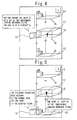
- Figure 4 is a diagram showing the condition of a car of an elevator, in which the elevator controller in Embodiment 1 of the present invention is used, the elevator being at a standstill at an emergency landing entrance floor.
- Figure 5 is a diagram showing the condition of a user of the elevator, in which the elevator controller in Embodiment 1 of the present invention is used, who is shut up in the emergency landing entrance floor.
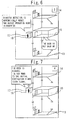
- Figure 6 is a diagram showing the condition of the user af the elevator, in which the elevator controller in Embodiment 1 of the present invention is used, during rescue from the emergency landing entrance floor.
- Figure 7 is a diagram showing the condition of the user shut up in the emergency landing entrance floor of the elevator, in which the elevator controller in Embodiment 1 of the present invention is used, during movement to his or her initial destination floor.
- reference numeral 13 denotes the first floor of a building. This first floor 13 is a service floor of the normal operation mode.
- Reference numeral 14 denotes the 10th floor. Also this 10th floor 14 is a service floor of the normal operation mode.
- Reference numeral 15 denotes an emergency landing entrance floor. This emergency landing entrance floor 15 is provided between the first floor 13 and the 10th floor 14. This emergency landing entrance floor 15 is not a service floor of the normal operation mode.
- the user 17 can escape to the emergency landing entrance floor 15.
- disaster detection is automatically reset and the elevator operation mode returns to the normal operation mode instead of becoming the rescue operation mode, as shown in Figure 5 , the car 16 runs to the service floor of the normal operation mode. As a result of this, the user 17 becomes shut up in the emergency landing entrance floor 15.
- the door open/close controller 8 causes the elevator to open its doors for a given time at the nearest emergency landing entrance floor.
- the hall indication/informing controller 12 informs an informing device, which is provided in the hall 11 of the emergency landing entrance floor 15 for which the door open/close controller 8 causes the doors to be opened for a given time, to the effect that the elevator can be used.
- the operation mode controller 5 registers car calls corresponding to the car calls stored in the car call storage device 9. Therefore, the user 17 who has escaped to the emergency landing entrance floor 15 can go to the initial destination floor using the elevator without performing a registration operation again.
- the operation mode controller 5 switches the operation mode from the normal operation mode to the emergency operation mode.
- the operation mode controller 5 maintains the operation mode at the normal operation mode, Consequently, it is possible to efficiently operate the elevator without performing an unnecessary rescue operation.
- the configuration is such that an indication/informing device provided in the hall 11 of the emergency landing entrance floor 15, for which the door open/close controller 8 causes the doors to be opened for a given time, is caused to provide information to the effect that the elevator can be used.
- the configuration may be such that an indication/informing device in the car is caused to provide information to the effect that the elevator can be used.
- the elevator controller of the present invention can be applied to an elevator which achieves an early stop at the nearest floor.
Landscapes
- Engineering & Computer Science (AREA)
- Life Sciences & Earth Sciences (AREA)
- Environmental & Geological Engineering (AREA)
- General Life Sciences & Earth Sciences (AREA)
- Geology (AREA)
- Remote Sensing (AREA)
- Automation & Control Theory (AREA)
- Maintenance And Inspection Apparatuses For Elevators (AREA)
- Indicating And Signalling Devices For Elevators (AREA)
Applications Claiming Priority (1)
| Application Number | Priority Date | Filing Date | Title |
|---|---|---|---|
| PCT/JP2009/057587 WO2010119525A1 (fr) | 2009-04-15 | 2009-04-15 | Appareil de commande pour ascenseur |
Publications (2)
| Publication Number | Publication Date |
|---|---|
| EP2420467A1 true EP2420467A1 (fr) | 2012-02-22 |
| EP2420467A4 EP2420467A4 (fr) | 2017-06-14 |
Family
ID=42982209
Family Applications (1)
| Application Number | Title | Priority Date | Filing Date |
|---|---|---|---|
| EP09843306.3A Withdrawn EP2420467A4 (fr) | 2009-04-15 | 2009-04-15 | Appareil de commande pour ascenseur |
Country Status (6)
| Country | Link |
|---|---|
| US (1) | US8800722B2 (fr) |
| EP (1) | EP2420467A4 (fr) |
| JP (1) | JP5338901B2 (fr) |
| KR (1) | KR101271297B1 (fr) |
| CN (1) | CN102395520B (fr) |
| WO (1) | WO2010119525A1 (fr) |
Families Citing this family (7)
| Publication number | Priority date | Publication date | Assignee | Title |
|---|---|---|---|---|
| GB2517384B (en) * | 2012-06-04 | 2018-03-07 | Otis Elevator Co | Elevator rope sway mitigation |
| JP6222162B2 (ja) * | 2015-04-20 | 2017-11-01 | 三菱電機ビルテクノサービス株式会社 | エレベータ装置及びエレベータの復旧方法 |
| KR101846640B1 (ko) | 2016-01-25 | 2018-04-06 | 엘에스산전 주식회사 | 엘리베이터의 운전 제어 방법 |
| US11643302B2 (en) * | 2017-11-22 | 2023-05-09 | Otis Elevator Company | Sensing and notifying device for elevator emergencies |
| WO2020031331A1 (fr) * | 2018-08-09 | 2020-02-13 | 三菱電機株式会社 | Dispositif d'ascenseur |
| US11661312B2 (en) * | 2019-01-29 | 2023-05-30 | Otis Elevator Company | Hoisting rope monitoring device |
| DE102020206478A1 (de) * | 2020-05-25 | 2021-11-25 | Robert Bosch Gesellschaft mit beschränkter Haftung | Steuervorrichtung für einen Stromrichter, elektrisches Antriebssystem und Verfahren zum Einstellen eines sicheren Betriebszustandes |
Family Cites Families (14)
| Publication number | Priority date | Publication date | Assignee | Title |
|---|---|---|---|---|
| JPS50132640A (fr) * | 1974-03-12 | 1975-10-21 | ||
| US4157133A (en) * | 1978-04-24 | 1979-06-05 | Westinghouse Electric Corp. | Elevator system |
| JPS5637969A (en) * | 1979-09-05 | 1981-04-11 | Mitsubishi Electric Corp | Operating device for elevator when earthquake |
| JP3355683B2 (ja) * | 1993-03-02 | 2002-12-09 | 三菱電機株式会社 | エレベーターの地震時運転装置 |
| JPH08337370A (ja) | 1995-06-15 | 1996-12-24 | Hitachi Ltd | エレベータの運転制御装置 |
| JP3728357B2 (ja) * | 1996-11-15 | 2005-12-21 | 三菱電機株式会社 | エレベーターの弱者運転装置 |
| JPH10182029A (ja) * | 1996-12-25 | 1998-07-07 | Toshiba Elevator Kk | エレベータ制御装置 |
| JP2002068629A (ja) * | 2000-08-28 | 2002-03-08 | Hitachi Building Systems Co Ltd | エレベーターの地震時管制運転装置 |
| JP2006290509A (ja) * | 2005-04-08 | 2006-10-26 | Mitsubishi Electric Corp | エレベーターの制御装置 |
| FI118332B (fi) * | 2005-10-14 | 2007-10-15 | Kone Corp | Hissijärjestelmä |
| US7926620B2 (en) * | 2006-08-29 | 2011-04-19 | Mitsubishi Electric Corporation | Elevator control apparatus and control method |
| US8616339B2 (en) * | 2008-12-08 | 2013-12-31 | Mitsubishi Electric Corporation | Elevator control device |
| US8230980B2 (en) * | 2009-12-31 | 2012-07-31 | Inventio Ag | Method of operating elevators during emergency situations |
| FI125122B (fi) * | 2010-02-01 | 2015-06-15 | Kone Corp | Hissijärjestelmä |
-
2009
- 2009-04-15 JP JP2011509125A patent/JP5338901B2/ja not_active Expired - Fee Related
- 2009-04-15 KR KR1020117019588A patent/KR101271297B1/ko not_active Expired - Fee Related
- 2009-04-15 CN CN200980158687.9A patent/CN102395520B/zh not_active Expired - Fee Related
- 2009-04-15 EP EP09843306.3A patent/EP2420467A4/fr not_active Withdrawn
- 2009-04-15 WO PCT/JP2009/057587 patent/WO2010119525A1/fr not_active Ceased
- 2009-04-15 US US13/203,445 patent/US8800722B2/en not_active Expired - Fee Related
Non-Patent Citations (1)
| Title |
|---|
| See references of WO2010119525A1 * |
Also Published As
| Publication number | Publication date |
|---|---|
| KR20110108408A (ko) | 2011-10-05 |
| WO2010119525A1 (fr) | 2010-10-21 |
| US8800722B2 (en) | 2014-08-12 |
| US20110303495A1 (en) | 2011-12-15 |
| CN102395520B (zh) | 2014-01-29 |
| JPWO2010119525A1 (ja) | 2012-10-22 |
| KR101271297B1 (ko) | 2013-06-04 |
| EP2420467A4 (fr) | 2017-06-14 |
| CN102395520A (zh) | 2012-03-28 |
| JP5338901B2 (ja) | 2013-11-13 |
Similar Documents
| Publication | Publication Date | Title |
|---|---|---|
| JP5452505B2 (ja) | エレベータシステム | |
| US8800722B2 (en) | Elevator controller | |
| US7461723B2 (en) | Fire control system of elevator | |
| JP5516742B2 (ja) | エレベーターのモニター制御装置 | |
| CN113811502B (zh) | 移动体的移动控制系统 | |
| EP1930279B1 (fr) | Module de commande d ascenseur et procede de fonctionnement d ascenseur | |
| EP2557062A1 (fr) | Dispositif de commande pour ascenseur | |
| CN102381604A (zh) | 电梯装置 | |
| US20120181115A1 (en) | Elevator system | |
| CN104379481B (zh) | 电梯的控制装置及电梯的控制方法 | |
| JP5586785B2 (ja) | エレベータ装置 | |
| JP2003341955A (ja) | エレベータの火災時救出運転装置 | |
| JP6824466B2 (ja) | エレベーター | |
| WO2010067406A1 (fr) | Dispositif de commande d’ascenseur | |
| JP6141101B2 (ja) | エレベーター制御装置およびエレベーター制御方法 | |
| CN109132740B (zh) | 电梯装置及其控制方法 | |
| JPS6122673B2 (fr) | ||
| JP5955517B2 (ja) | エレベータシステム、エレベータの運転制御装置、およびエレベータの運転制御方法 | |
| JP2011153019A (ja) | エレベータの制御装置 | |
| CN102883982A (zh) | 电梯控制装置 | |
| JP5721295B1 (ja) | エレベータ制御装置 | |
| WO2019064371A1 (fr) | Dispositif d'entrée d'étage de destination d'arrivée pour ascenseurs, système de commande d'ascenseur et système d'ascenseur | |
| JPS583188Y2 (ja) | カサイジ ノ ヒナンアンナイソウチ | |
| JP4353750B2 (ja) | エレベーター制御装置 | |
| JP2010024003A (ja) | エレベーターの制御装置 |
Legal Events
| Date | Code | Title | Description |
|---|---|---|---|
| PUAI | Public reference made under article 153(3) epc to a published international application that has entered the european phase |
Free format text: ORIGINAL CODE: 0009012 |
|
| 17P | Request for examination filed |
Effective date: 20110908 |
|
| AK | Designated contracting states |
Kind code of ref document: A1 Designated state(s): AT BE BG CH CY CZ DE DK EE ES FI FR GB GR HR HU IE IS IT LI LT LU LV MC MK MT NL NO PL PT RO SE SI SK TR |
|
| DAX | Request for extension of the european patent (deleted) | ||
| RA4 | Supplementary search report drawn up and despatched (corrected) |
Effective date: 20170512 |
|
| RIC1 | Information provided on ipc code assigned before grant |
Ipc: B66B 1/34 20060101ALI20170508BHEP Ipc: B66B 3/00 20060101ALI20170508BHEP Ipc: B66B 13/14 20060101ALI20170508BHEP Ipc: B66B 5/02 20060101AFI20170508BHEP |
|
| STAA | Information on the status of an ep patent application or granted ep patent |
Free format text: STATUS: THE APPLICATION HAS BEEN WITHDRAWN |
|
| 18W | Application withdrawn |
Effective date: 20180912 |