EP2420609B1 - Laugenpumpe für wasserführende Haushaltgeräte und wasserführendes Haushaltgerät - Google Patents
Laugenpumpe für wasserführende Haushaltgeräte und wasserführendes Haushaltgerät Download PDFInfo
- Publication number
- EP2420609B1 EP2420609B1 EP11176799.2A EP11176799A EP2420609B1 EP 2420609 B1 EP2420609 B1 EP 2420609B1 EP 11176799 A EP11176799 A EP 11176799A EP 2420609 B1 EP2420609 B1 EP 2420609B1
- Authority
- EP
- European Patent Office
- Prior art keywords
- water
- drain pump
- suction pipe
- pump
- suction
- Prior art date
- Legal status (The legal status is an assumption and is not a legal conclusion. Google has not performed a legal analysis and makes no representation as to the accuracy of the status listed.)
- Active
Links
Images

Classifications
-
- D—TEXTILES; PAPER
- D06—TREATMENT OF TEXTILES OR THE LIKE; LAUNDERING; FLEXIBLE MATERIALS NOT OTHERWISE PROVIDED FOR
- D06F—LAUNDERING, DRYING, IRONING, PRESSING OR FOLDING TEXTILE ARTICLES
- D06F39/00—Details of washing machines not specific to a single type of machines covered by groups D06F9/00 - D06F27/00
- D06F39/08—Liquid supply or discharge arrangements
- D06F39/083—Liquid discharge or recirculation arrangements
-
- A—HUMAN NECESSITIES
- A47—FURNITURE; DOMESTIC ARTICLES OR APPLIANCES; COFFEE MILLS; SPICE MILLS; SUCTION CLEANERS IN GENERAL
- A47L—DOMESTIC WASHING OR CLEANING; SUCTION CLEANERS IN GENERAL
- A47L15/00—Washing or rinsing machines for crockery or tableware
- A47L15/42—Details
- A47L15/4214—Water supply, recirculation or discharge arrangements; Devices therefor
- A47L15/4225—Arrangements or adaption of recirculation or discharge pumps
-
- F—MECHANICAL ENGINEERING; LIGHTING; HEATING; WEAPONS; BLASTING
- F04—POSITIVE - DISPLACEMENT MACHINES FOR LIQUIDS; PUMPS FOR LIQUIDS OR ELASTIC FLUIDS
- F04D—NON-POSITIVE-DISPLACEMENT PUMPS
- F04D29/00—Details, component parts, or accessories
- F04D29/40—Casings; Connections of working fluid
- F04D29/42—Casings; Connections of working fluid for radial or helico-centrifugal pumps
- F04D29/44—Fluid-guiding means, e.g. diffusers
- F04D29/445—Fluid-guiding means, e.g. diffusers especially adapted for liquid pumps
-
- F—MECHANICAL ENGINEERING; LIGHTING; HEATING; WEAPONS; BLASTING
- F04—POSITIVE - DISPLACEMENT MACHINES FOR LIQUIDS; PUMPS FOR LIQUIDS OR ELASTIC FLUIDS
- F04D—NON-POSITIVE-DISPLACEMENT PUMPS
- F04D9/00—Priming; Preventing vapour lock
- F04D9/001—Preventing vapour lock
- F04D9/002—Preventing vapour lock by means in the very pump
- F04D9/003—Preventing vapour lock by means in the very pump separating and removing the vapour
Definitions
- the present invention relates to a drain pump for water-bearing household appliances according to the preamble of claim 1 and to a water-bearing household appliance, in particular a laundry treatment machine, with such a drain pump.
- the working liquid is sucked in through the pumping system by means of a liquid pump, which is connected to the container receiving the working liquid via a drain line, and via an upward line on the pressure side of the pump into the sewage network or for the further Work process conveyed into the work container.
- the amount of air or foam affects both the flow rate and the delivery pressure of the pump. Increasing air or foam proportions tend to lead to decreasing flow rates and pump pressures, but also to decreasing connected loads for pump operation.
- sucked-in air bubbles remain in the suction pipe of the pump and thus impair the delivery flow and the delivery pressure of the pump sinks.
- the cross-section in the suction tube through which the liquid flows narrows and the suction power decreases.
- the flow is set in rotation over a longer area or introduced rotating into the pressure chamber of the pump.
- the lighter medium, air collects in the center of the intake pipe, where it forms vortices that can spread over the entire length of the intake pipe.
- the vortex created in the suction pipe prevents the liquid to be pumped from being pumped out. This process often leads to the point that the flow can completely break off. The result is malfunctions when pumping, which can only be counteracted by targeted additional measures.
- a mechanical variant of the solution is proposed for removing the foam in a dishwasher.
- a centrifuge with a plate-shaped bottom part is provided in the circulation circuit.
- the mixture of foam and washing solution enters the centrifuge axially and is accelerated radially outwards on a spiral path by the plate-shaped bottom part. Due to the very different densities of water and foam, centrifugal forces of different strengths act on the two components of the washing liquor, whereby the foam is destroyed during acceleration.
- the DE 195 37 944 A1 relates to an emptying pump to pump lye from washing machines or the like from a tub.
- a so-called foreign body trap which is separated from the pump housing by an intermediate plate, is connected upstream of the pump housing. Air that collects in the pump housing can get into the foreign body trap through at least one ventilation opening in the intermediate plate and escape from it through a ventilation opening provided in the outer wall of the foreign body trap.
- a drain pump of the type mentioned is known, in the pump chamber of which there is a preliminary guide device with a hollow cylindrical part (suction pipe) lying essentially horizontally in the chamber.
- suction pipe a hollow cylindrical part lying essentially horizontally in the chamber.
- at least one flat wing is arranged on the outer surface of the suction pipe, which extends in the axial direction of the suction pipe.
- the invention is based on the object of modifying known drain pumps with simple means so that their delivery rate with a high proportion of air and foam is improved and to create a water-bearing household appliance with a drain pump, which ensures a stable delivery process with short program times.
- the drain pump designed according to the invention With the drain pump designed according to the invention, their ventilation is improved and the flow rate stabilized.
- the proposed measures on the feed pump can avoid interruptions in pumping, the entire pumping process can be run through in a shortened time, even with a high proportion of air or foam in the working fluid to be pumped, with stable operating states and thus the maximum possible flow rate.
- the pump shows an improved start-up behavior. The noise level during the start-up phase is greatly reduced. Another advantage is that the shorter and more efficient pumping-out processes reduce wear on the pump.
- the drain pump according to the invention has an overhead ventilation duct in the suction pipe which connects the pump antechamber with the pump pressure chamber.
- the air bubbles in the conveying flow can exit the suction pipe via the ventilation duct and be diverted against the incoming working fluid via the upwardly inclined drainage hose.
- At least one baffle wall is arranged radially on the outside of the intake pipe parallel to the ventilation duct.
- the arrangement of the baffles on the intake pipe acts as a swirl brake and thus prevents the formation of eddies.
- at least one inclined or curved axial rib is arranged on the outside of the intake pipe. The inclined or curved axial ribs are aligned with the connection piece on the suction side. The ribs result in aerodynamic advantages which lead to a further improvement in the pumping process.
- the water-carrying household appliance in particular a laundry washing machine, comprises the drain pump according to the invention, which is arranged in a connected solution drain system of the household appliance.
- the use of such a drain pump is therefore particularly advantageous in washing machines, since such a mixture of water and foam can also be conveyed away quickly and reliably. In this way, a stable process sequence can be ensured even with laundry washing machines with a larger drum volume and shorter program times.
- the Figures 1 and 2 show the drain pump 1 of a laundry washing machine 17 consisting of a pump housing 2 with an impeller 9, which is driven by a motor 8, and a filter insert 3 which can be connected to the pump housing 2 in a liquid-proof manner.
- the fluid connection between the drain pump 1 and the tub takes place via a drain hose 7 which is attached to the suction port 5 of the pump housing 2 with a slight incline towards the tub.
- the drainage hose 6 is attached to the connection piece 4 of the drain pump 1 and is connected to the pump 1 in a mechanically solid and liquid-proof manner.
- the pumped-off liquid is discharged to the outside via the drainage hose 6.
- the partition 14 between the antechamber 16 and the pressure chamber 15 of the drain pump 1 has a circular opening in the center, to which the suction pipe 13 is attached.
- it is provided with an axially aligned vent duct 11 located at the top.
- two baffle walls 10 are inserted parallel to the ventilation duct 11, angularly offset by approximately 180 °.
- the baffle walls 10 act as a swirl brake, whereby the formation of eddies in the liquid to be conveyed can be suppressed.
- curved ribs 12 are arranged on the outer jacket of the intake pipe 13 .
- the curved ribs 12 have a positive effect on the flow behavior in the antechamber 16, especially when a mixture of foam and water is to be conveyed.
- the suction pipe 13 is made of a plastic.
- the baffle walls 10 and the curved ribs 12 are formed from the same material consisting of the intake pipe.
- the implementation of the invention is very simple. The effort required is limited to a structural change in the filter insert 3 and a change in the production tools required for this.
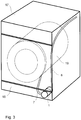
- the Fig. 3 shows a laundry washing machine 17 with the drain pump described above, which is arranged in the lower front area, in or behind a front panel 18 and which is connected to a drain hose 7 from a tub 19 and to an emptying hose 6, through which the liquor to be pumped out of the washing machine is discharged can be.
Landscapes
- Engineering & Computer Science (AREA)
- Textile Engineering (AREA)
- Mechanical Engineering (AREA)
- General Engineering & Computer Science (AREA)
- Water Supply & Treatment (AREA)
- Detail Structures Of Washing Machines And Dryers (AREA)
- Structures Of Non-Positive Displacement Pumps (AREA)
Description
- Die vorliegende Erfindung bezieht sich auf eine Laugenpumpe für wasserführende Haushaltgeräte gemäß dem Oberbegriff des Patentanspruchs 1 und auf ein wasserführendes Haushaltgerät, insbesondere eine Wäschebehandlungsmaschine, mit einer solchen Laugenpumpe.
- Bei wasserführenden Haushaltgeräten der in Rede stehenden Art wird durch das Abpumpsystem mittels einer Flüssigkeitspumpe, die über eine Ablaufleitung mit dem die Arbeitsflüssigkeit aufnehmenden Behälter verbunden ist, die Arbeitsflüssigkeit angesaugt und über eine nach oben gerichtete Leitung auf der Druckseite der Pumpe ins Abwassernetz oder für den weiteren Arbeitsprozess in den Arbeitsbehälter befördert.
- Im Folgenden wird wegen der größeren Bedeutung der Erfindung für Wäschewaschmaschinen, insbesondere Geräten mit vergrößertem Trommelvolumen und verkürzten Programmzeiten, nur auf die Funktion des Erfindungsgegenstandes für derartige Geräte Bezug genommen. Die Anwendbarkeit der Erfindung bei anderen Haushaltgeräten wie beispielsweise Geschirrspülern wird dadurch nicht eingeschränkt.
- Bei Wäschewaschmaschinen mit großem Trommelvolumen und verkürzten Programmzeiten führen der höhere Wasseranfall insbesondere im Schleuderhochlauf und die verkürzten Prozessabläufe im Schleuderprofil zu erhöhten Anforderungen an die Laugenpumpe des Gerätes. Standardpumpen stoßen bei derartig hohen Anforderungen an ihre Grenzen. Der Luft- und Schaumanteil in dem von der Pumpe zu fördernden Flüssigkeitsstrom ist insbesondere beim Schleuderhochlauf besonders hoch. Es kommt zu Störungen im Abpumpsystem und damit zu Unterbrechungen im Programmablauf der Wäschewaschmaschine.
- Die Höhe des Luft- bzw. Schaumanteils beeinflusst sowohl den Förderstrom als auch den Förderdruck der Pumpe. Dabei führen steigende Luft- bzw. Schaumanteile tendenziell zu abnehmenden Förderströmen und Pumpendrücken, aber auch zu sinkenden Anschlussleistungen für den Pumpenbetrieb. Bei den herkömmlich verwendeten Laugenpumpen mit in der Regel radialen, gerade verlaufenden Schaufeln verharren angesaugte Luftbläschen im Saugrohr der Pumpe und beeinträchtigen somit den Förderstrom, der Förderdruck der Pumpe sinkt. Durch die im Filtereinsatz verharrenden Schaumanteile und Luftbläschen verengt sich der flüssigkeitsdurchströmte Querschnitt im Saugrohr und die Saugleistung sinkt.
- Im Strömungsquerschnitt des Saugrohrs/Saugmunds der Laugenpumpe wird konstruktionsbedingt die Strömung über einen längeren Bereich in Rotation versetzt bzw. rotierend in die Druckkammer der Pumpe eingeleitet. Das leichtere Medium Luft sammelt sich zentral im Ansaugrohr und bildet dort Wirbel, die sich über die gesamte Saugrohrlänge ausbreiten können. Der im Saugrohr entstandene Wirbel behindert ein Abpumpen der zu fördernden Flüssigkeit. Oft führt dieser Vorgang so weit, dass der Förderstrom komplett abreißen kann. Die Folge sind Betriebsstörungen beim Abpumpen, denen nur durch zielgerichtete zusätzliche Maßnahmen entgegen gewirkt werden kann.
- Aus dem Stand der Technik sind zur Lösung dieses Problems Verfahren bekannt, die die Schaumbildung verringern und/oder die Schaummenge reduzieren. Als ein Beispiel wird das in der
DE 102 34 472 A1 beschriebene Verfahren angeführt. Mittels geeigneter Sensoren wird der Schaum im Laugenbehälter einer Wäschewaschmaschine detektiert. Die Sensorsignale werden gemäß dem bekannten Verfahren über die Zeit erfasst und geräteintern ausgewertet. Abhängig vom Ergebnis der Auswertung werden programmgesteuert geeignete Schaumbehandlungsmaßnahmen eingeleitet. Als geeignete Maßnahmen werden in der genannten Offenlegungsschrift eine Veränderung der Drehzahl der Trommel beim Schleudern, eine Temperaturerhöhung der Flüssigkeit im Laugenbehälter und die Zuführung einer bestimmten Menge kalten und/oder warmen Wassers aufgeführt. - Es zeigt sich, dass durch eine entsprechende Steuerung des Waschprozesses der Luft- und Schaumanteil im Förderstrom reduziert werden kann. Mit den beschriebenen Maßnahmen zur Schaumreduzierung oder ähnlichen dieser Art, die in weiteren Schriften offenbart sind, ist der Nachteil verbunden, dass die Programmzeit - insbesondere der Schleudergang - erheblich verlängert wird. Ein weiterer wichtiger Nachteil dieser bekannten Verfahren besteht darin, dass mit der Zuführung von zusätzlichem Wasser, das am eigentlichen Waschprozess nicht beteiligt ist, der Wasserverbrauch steigt. Mit der Maßnahme einer Temperaturerhöhung der Arbeitsflüssigkeit im Laugenbehälter erhöht sich zusätzlich der Energieverbrauch der Wäschewaschmaschine.
- Diese Mängel zu beseitigen, wird in der
DE 197 52 296 A1 vorgeschlagen, zwischen Zu- und Ablauf der Entleerungspumpe eine Bypassleitung anzuordnen. Über die Bypassleitung wird der Pumpenkammer immer eine gewisse Teilwassermenge aus dem Entleerungsschlauch zugeleitet. Da diese Teilwassermenge nur einen geringen Luftanteil enthält, kann somit der Pumpbetrieb stabilisiert werden. - In der
DE 41 33 554 A1 wird zur Beseitigung des Schaums in einer Geschirrspülmaschine eine mechanische Lösungsvariante vorgeschlagen. Dazu ist im Umwälzkreislauf eine Zentrifuge mit einem tellerförmigen Bodenteil vorgesehen. Das Gemisch aus Schaum und Spülflotte tritt axial in die Zentrifuge ein und wird durch den tellerförmigen Bodenteil auf einer Spiralbahn radial nach außen beschleunigt. Durch die sehr unterschiedlichen Dichten von Wasser und Schaum wirken auf die beiden Bestandteile der Spülflotte verschieden starke Zentrifugalkräfte, wodurch der Schaum während der Beschleunigung zerstört wird. - Bei den beiden letztgenannten Lösungen werden zur Stabilisierung des Ab- bzw. Umpumpprozesses zusätzliche Bauteile eingesetzt. Damit ist in nachteiliger Weise ein höherer Aufwand verbunden, insbesondere bei der Gerätemontage. Für den Betrieb der Zentrifuge ist außerdem ein zusätzlicher Antrieb erforderlich, durch den die Kosten und der Energieverbrauch des Gerätes steigen.
- Die
DE 195 37 944 A1 betrifft eine Entleerungspumpe, um aus Waschmaschinen oder dgl. Lauge aus einem Laugenbehälter abzupumpen. Dem Pumpengehäuse ist eine so genannte Fremdkörperfalle vorgeschaltet, die durch eine Zwischenplatte von dem Pumpengehäuse getrennt ist. Durch wenigstens eine Belüftungsöffnung in der Zwischenplatte kann im Pumpengehäuse sich ansammelnde Luft in die Fremdkörperfalle gelangen und aus dieser durch eine Entlüftungsöffnung entweichen, die in der Außenwand der Fremdkörperfalle vorgesehen ist. - Aus der
DE 10 2008 054 998 B3 ist eine Laugenpumpe der eingangs genannten Art bekannt, in deren Pumpenkammer eine Vorleiteinrichtung mit einem in der Kammer im wesentlichen horizontal liegenden hohlen zylindrischen Teil (Ansaugrohr) vorgesehen ist. Zur Verbesserung der Förderleistung durch eine Optimierung der Strömungseigenschaften aufschäumender Waschlaugen bei zugleich reduzierter Schallemission ist auf der äußeren Oberfläche des Ansaugrohres wenigstens ein flacher Flügel angeordnet, der sich in axialer Richtung des Ansaugrohres erstreckt. - Der Erfindung liegt die Aufgabe zugrunde, bekannte Laugenpumpen mit einfachen Mitteln so zu verändern, dass deren Förderleistung bei hohem Luft- und Schaumanteil verbessert wird und ein wasserführendes Haushaltsgerät mit einer Laugenpumpe zu schaffen, welches bei kurzen Programmzeiten einen stabilen Förderprozess sichert.
- Erfindungsgemäß wird die Aufgabe durch die im kennzeichnenden Teil des Patentanspruchs 1 und des Patentanspruchs 7 genannten Merkmale gelöst. Vorteilhafte Ausgestaltungen der Erfindung sind in den Unteransprüchen enthalten.
- Mit der erfindungsgemäß gestalteten Laugenpumpe wird deren Belüftung verbessert und der Förderstrom stabilisiert. Durch die vorgeschlagenen Maßnahmen an der Förderpumpe können Pumpabbrüche vermieden werden, der gesamte Abpumpprozess kann auch bei hohem Luft- bzw. Schaumanteil in der zu fördernden Arbeitsflüssigkeit mit stabilen Betriebszuständen und damit maximal möglichem Förderstrom in einer verkürzten Zeit durchfahren werden. Darüber hinaus zeigt die Pumpe ein verbessertes Anlaufverhalten. Der Geräuschpegel während der Anlaufphase ist stark reduziert. Weiterhin ist von Vorteil, dass durch die verkürzten und effizienteren Abpumpvorgänge der Verschleiß der Pumpe verringert wird.
- Als wesentliches Merkmal weist die erfindungsgemäße Laugenpumpe im Saugrohr, das die Pumpenvorkammer mit der Pumpendruckkammer verbindet, einen oben liegenden Entlüftungskanal auf. Die Luftbläschen im Förderstrom können über den Entlüftungskanal aus dem Saugrohr austreten und gegen die zuströmende Arbeitsflüssigkeit über den nach oben geneigten Ablaufschlauch abgeleitet werden.
- In Ausgestaltung der Erfindung ist außen am Ansaugrohr parallel zum Entlüftungskanal mindestens eine Prallwand radial angeordnet. Die Anordnung der Prallwände am Ansaugrohr wirkt als Drallbremse und verhindert dadurch die Ausbildung von Wirbeln. In weiterer Ausgestaltung der Erfindung ist außen am Ansaugrohr mindestens eine schräge oder geschwungene axiale Rippe angeordnet. Die schrägen bzw. geschwungenen axialen Rippen sind zum Anschlussstutzen auf der Saugseite ausgerichtet. Durch die Rippen ergeben sich strömungstechnische Vorteile, die zu einer weiteren Verbesserung des Abpumpvorgangs führen.
- Das wasserführende Haushaltgerät, insbesondere eine Wäschewaschmaschine, umfasst die erfindungsgemäße Laugenpumpe, welche in einem angeschlossenen Laugenablaufsystem des Haushaltgeräts angeordnet ist. Zum Reinigen von Wäsche oder Geschirr werden in Waschmaschinen notorisch Wasser und Waschsubstanzen eingesetzt, wobei während des Behandlungsprozesses viel Schaum entstehen kann. Daher ist der Einsatz einer solchen Laugenpumpe insbesondere bei Waschmaschinen von Vorteil, da auch ein solches Gemisch aus Wasser und Schaum schnell und zuverlässig abgefördert werden kann. Somit kann auch bei Wäschewaschmaschinen mit größerem Trommelvolumen und verkürzten Programmzeiten ein stabiler Prozessablauf sicher gestellt werden.
- Unter Bezugnahme auf die aufgeführten Zeichnungen wird die Erfindung nachstehend an einem Ausführungsbeispiel näher erläutert. Es zeigen:
- Fig. 1:
- Eine Laugenpumpe in Draufsicht,
- Fig. 2 :
- Pumpengehäuse und Filtereinsatz in Perspektivdarstellung und
- Fig. 3:
- eine perspektivische schematische Ansicht einer Wäschewaschmaschine mit durchsichtig dargestelltem Gehäuse und einem an einen Laugenbehälter angeschlossenen Laugenablaufsystem
- Die
Figuren 1 und 2 zeigen die Laugenpumpe 1 einer Wäschewaschmaschine 17 bestehend aus einem Pumpengehäuse 2 mit einem Flügelrad 9, das von einem Motor 8 angetrieben wird und einem Filtereinsatz 3, der mit dem Pumpengehäuse 2 flüssigkeitssicher verbindbar ist. Die fluide Verbindung der Laugenpumpe 1 mit dem Laugenbehälter erfolgt über einen Ablaufschlauch 7, der mit einer leichten Steigung zum Laugenbehälter am Ansaugstutzen 5 des Pumpengehäuses 2 aufgesteckt ist. Druckseitig ist am Anschlussstutzen 4 der Laugenpumpe 1 der Entleerungsschlauch 6 aufgesteckt und mit der Pumpe 1 mechanisch fest und flüssigkeitssicher verbunden. Über den Entleerungsschlauch 6 wird die abgepumpte Flüssigkeit nach außen abgeführt. - Die Trennwand 14 zwischen der Vorkammer 16 und der Druckkammer 15 der Laugenpumpe 1 weist mittig eine kreisrunde Öffnung auf, an die das Ansaugrohr 13 angesetzt ist. Zur Entlüftung des Ansaugrohres 13 ist dieses mit einem oben liegenden axial ausgerichteten Entlüftungskanal 11 versehen. Am Außenmantel des Ansaugrohres 13 sind parallel zum Entlüftungskanal 11 etwa um 180° winkelversetzt zwei Prallwände 10 eingesetzt. Die Prallwände 10 wirken als Drallbremse, wodurch die Ausbildung von Wirbeln in der zu fördernden Flüssigkeit unterdrückt werden kann.
- Zusätzlich sind am Außenmantel des Ansaugrohres 13 zwei geschwungene, zum Saugsstutzen 5 ausgerichtete Rippen 12 angeordnet. Die geschwungenen Rippen 12 wirken sich positiv auf das Strömungsverhalten in der Vorkammer 16 aus, insbesondere bei einem zu fördernden Gemisch aus Schaum und Wasser.
- Das Ansaugrohr 13 ist aus einem Kunststoff gefertigt. Die Prallwände 10 und die geschwungenen Rippen 12 sind aus dem gleichen Material bestehend am Ansaugrohr angeformt. Wie aus der Konstruktion des Filtereinsatzes 3 erkennbar, ist die Umsetzung der Erfindung sehr einfach. Der notwendige Aufwand beschränkt sich auf eine konstruktive Änderung des Filtereinsatzes 3 und eine Änderung der dafür erforderlichen Fertigungswerkzeuge.
- Die
Fig. 3 zeigt eine Wäschewaschmaschine 17 mit der vorstehend beschriebenen Laugenpumpe, welche im unteren vorderen Bereich, in oder hinter einer Frontblende 18 angeordnet ist und welche mit einem Ablaufschlauch 7 aus einem Laugenbehälter 19 und mit einem Entleerungsschlauch 6 verbunden ist, durch welche abzupumpende Lauge aus der Wäschewaschmaschine abgeführt werden kann. -
- 1.
- Laugenpumpe
- 2.
- Pumpengehäuse
- 3.
- Filtereinsatz
- 4.
- Anschlussstutzen auf der Druckseite
- 5.
- Saugstutzen
- 6.
- Entleerungsschlauch
- 7.
- Ablaufschlauch
- 8.
- Motor
- 9.
- Flügelrad
- 10.
- Prallwand
- 11.
- Entlüftungskanal
- 12.
- Geschwungene Rippe
- 13.
- Saugrohr
- 14.
- Trennwand
- 15.
- Druckkammer
- 16.
- Vorkammer
- 17.
- Wäschewaschmaschine
- 18.
- Frontblende
- 19.
- Laugenbehälter
Claims (7)
- Laugenpumpe (1) für wasserführende Haushaltgeräte (17) zum Abführen und/oder Umwälzen der Arbeitsflüssigkeit ausgerüstet mit Anschlussstutzen (5, 4) auf der Saugseite und auf der Druckseite und mit einem Ansaugrohr (13), dadurch gekennzeichnet, dass das Ansaugrohr (13) in der Pumpe (1) einen durchgehenden, oben liegenden, Entlüftungskanal (11) aufweist und der Anschlussstutzen (5) auf der Saugseite über einen nach oben geneigten Ablaufschlauch (7) des Haushaltsgeräts vebindbar ist.
- Laugenpumpe nach Anspruch 1, dadurch gekennzeichnet, dass außen am Ansaugrohr (13) parallel zum Entlüftungskanal (11) mindestens eine Prallwand (10) radial angeordnet ist.
- Laugenpumpe nach Anspruch 1, dadurch gekennzeichnet, dass außen am Ansaugrohr (13) parallel zum Entlüftungskanal (11) zwei radiale Prallwände (11) um etwa 180° versetzt angeordnet sind.
- Laugenpumpe nach Anspruch 1, dadurch gekennzeichnet, dass außen am Ansaugrohr (13) eine geschwungene axiale Rippe (12) angeordnet ist.
- Laugenpumpe nach Anspruch 1, dadurch gekennzeichnet, dass die geschwungene axiale Rippe (12) zum Anschlussstutzen (5) auf der Saugseite ausgerichtet ist.
- Laugenpumpe nach Anspruch 1, dadurch gekennzeichnet, dass das Ansaugrohr (13) mit den Prallwänden (11) und der geschwungenen axialen Rippe (12) einstückig gefertigt ist.
- Wasserführendes Haushaltgerät, insbesondere Wäschewaschmaschine, umfassend ein Laugenablaufsystem in dem eine Laugenpumpe (1) nach einem der vorstehenden Ansprüche angeordnet ist.
Priority Applications (1)
| Application Number | Priority Date | Filing Date | Title |
|---|---|---|---|
| PL11176799T PL2420609T3 (pl) | 2010-08-20 | 2011-08-08 | Pompa środka myjącego do prowadzących wodę urządzeń gospodarstwa domowego i prowadzące wodę urządzenie gospodarstwa domowego |
Applications Claiming Priority (1)
| Application Number | Priority Date | Filing Date | Title |
|---|---|---|---|
| DE102010039566A DE102010039566A1 (de) | 2010-08-20 | 2010-08-20 | Laugenpumpe für wasserführende Haushaltgeräte und wasserführendes Haushaltgerät |
Publications (3)
| Publication Number | Publication Date |
|---|---|
| EP2420609A2 EP2420609A2 (de) | 2012-02-22 |
| EP2420609A3 EP2420609A3 (de) | 2017-08-30 |
| EP2420609B1 true EP2420609B1 (de) | 2020-12-30 |
Family
ID=44677437
Family Applications (1)
| Application Number | Title | Priority Date | Filing Date |
|---|---|---|---|
| EP11176799.2A Active EP2420609B1 (de) | 2010-08-20 | 2011-08-08 | Laugenpumpe für wasserführende Haushaltgeräte und wasserführendes Haushaltgerät |
Country Status (3)
| Country | Link |
|---|---|
| EP (1) | EP2420609B1 (de) |
| DE (1) | DE102010039566A1 (de) |
| PL (1) | PL2420609T3 (de) |
Families Citing this family (5)
| Publication number | Priority date | Publication date | Assignee | Title |
|---|---|---|---|---|
| EP2746441A1 (de) | 2012-12-18 | 2014-06-25 | Miele & Cie. KG | Verfahren zum Betreiben eines wasserführenden Haushaltsgerätes und wasserführendes Haushaltsgerät |
| WO2015016939A1 (en) | 2013-08-02 | 2015-02-05 | Electrolux Home Products, Inc. | Pump plate for conditioning fluid flow in a dishwasher |
| DE102014210626B4 (de) * | 2014-06-04 | 2020-06-18 | BSH Hausgeräte GmbH | Haushaltsgerät mit einem Laugenbehälter |
| CN109779977B (zh) * | 2017-11-14 | 2022-07-12 | 青岛海尔洗涤电器有限公司 | 一种双头泵壳体结构及洗衣机 |
| KR102543851B1 (ko) * | 2018-05-16 | 2023-06-16 | 삼성전자주식회사 | 세탁기 |
Family Cites Families (7)
| Publication number | Priority date | Publication date | Assignee | Title |
|---|---|---|---|---|
| DE4133554A1 (de) | 1991-10-10 | 1993-04-15 | Bauknecht Hausgeraete | Haushaltgeraet, z. b. wasch- oder geschirrspuelmaschine |
| DE4302497A1 (de) * | 1993-01-29 | 1994-08-04 | Massindustrie Gmbh | Drehrichtungsunabhängige Strömungspumpe mit einem Synchronmotor |
| DE19537944A1 (de) * | 1995-10-12 | 1997-04-17 | Aeg Hausgeraete Gmbh | Entleerungspumpe für Waschmaschinen oder dergl. |
| DE19752296A1 (de) | 1997-11-26 | 1999-05-27 | Aeg Hausgeraete Gmbh | Trommelwaschmaschine |
| EP1024292B1 (de) * | 1999-01-26 | 2004-08-04 | Wilo Ag | Kreiselpumpe mit Gasabscheidekammer |
| DE10234472A1 (de) | 2002-07-29 | 2004-02-12 | BSH Bosch und Siemens Hausgeräte GmbH | Verfahren zum Beseitigen von Schaum im Laugenbehälter einer Trommelwaschmaschine |
| DE102008054998B3 (de) * | 2008-12-19 | 2010-06-17 | BSH Bosch und Siemens Hausgeräte GmbH | Waschmaschine, für die Waschmaschine geeignetes Pumpensystem sowie Verfahren zu ihrem Betrieb |
-
2010
- 2010-08-20 DE DE102010039566A patent/DE102010039566A1/de not_active Withdrawn
-
2011
- 2011-08-08 PL PL11176799T patent/PL2420609T3/pl unknown
- 2011-08-08 EP EP11176799.2A patent/EP2420609B1/de active Active
Non-Patent Citations (1)
| Title |
|---|
| None * |
Also Published As
| Publication number | Publication date |
|---|---|
| DE102010039566A1 (de) | 2012-02-23 |
| PL2420609T3 (pl) | 2021-06-28 |
| EP2420609A3 (de) | 2017-08-30 |
| EP2420609A2 (de) | 2012-02-22 |
Similar Documents
| Publication | Publication Date | Title |
|---|---|---|
| EP2495444B1 (de) | Pumpe | |
| DE102014222050B3 (de) | Wäschepflegegerät mit einer Laugenpumpe | |
| EP2348944B2 (de) | Pumpe für fluide | |
| DE102014206119B4 (de) | Verfahren zum Betreiben einer Pumpe in einem Haushaltsgerät und wasserführendes Haushaltsgerät | |
| DE102009046782A1 (de) | Wasserführendes Haushaltsgerät mit einer in zwei Betriebsarten steuerbaren Pumpe | |
| EP2420609A2 (de) | Laugenpumpe für wasserführende Haushaltgeräte und wasserführendes Haushaltgerät | |
| EP3351674B1 (de) | Wäschepflegegerät mit einer steuerung | |
| DE3934434A1 (de) | Waschmaschine | |
| DE102009002224B4 (de) | Wasserführendes Haushaltsgerät, insbesondere Geschirrspülmaschine | |
| EP1913262B1 (de) | Pumpengehäuse, pumpe und wasserführendes haushaltsgerät | |
| DE102008054998B3 (de) | Waschmaschine, für die Waschmaschine geeignetes Pumpensystem sowie Verfahren zu ihrem Betrieb | |
| EP3411520B1 (de) | Wäschepflegegerät mit einer pumpenansteuerung | |
| EP1973460B1 (de) | Geschirrspülmaschine | |
| DE102008016476A1 (de) | Hausgerät mit einer Pumpe zur Förderung eines Mediums | |
| DE102019117652A1 (de) | Waschmaschine mit Hydrozyklon und Verfahren zu deren Betrieb | |
| EP2746451A1 (de) | Verfahren zum Abpumpen einer Flüssigkeit aus einem wasserführenden Haushaltsgerät, insbesondere aus einer Waschmaschine, sowie wasserführendes Haushaltsgerät | |
| EP2464274B1 (de) | Wasserführendes hausgerät mit einer pumpe | |
| EP2227584B2 (de) | Wäschetrocknungsgerät | |
| DE10161300B4 (de) | Wäschebehandlungsmaschine in Form einer Waschmaschine oder eines Wäschetrockners | |
| DE10318862B4 (de) | Wasserführendes Haushaltgerät mit einer Entleerungspumpe sowie Entleerungspumpe | |
| DE102017211573A1 (de) | Verfahren zum Betrieb einer Waschmaschine mit verbesserter Pumpenzustandserkennung und hierzu geeignete Waschmaschine | |
| EP3545812B1 (de) | Geschirrspülmaschine, insbesondere haushaltsgeschirrspülmaschine | |
| DE4341215A1 (de) | Kreiselpumpe, insbesondere zur Verwendung als Umwälzpumpe für Geschirrspülmaschinen und Waschmaschinen | |
| WO2025056317A1 (de) | Pumpe und haushaltsgerät mit einer solchen pumpe | |
| EP1576291B1 (de) | Wasserführendes haushaltgerät mit einer entleerungspumpe sowie entleerungspumpe |
Legal Events
| Date | Code | Title | Description |
|---|---|---|---|
| AK | Designated contracting states |
Kind code of ref document: A2 Designated state(s): AL AT BE BG CH CY CZ DE DK EE ES FI FR GB GR HR HU IE IS IT LI LT LU LV MC MK MT NL NO PL PT RO RS SE SI SK SM TR |
|
| AX | Request for extension of the european patent |
Extension state: BA ME |
|
| PUAI | Public reference made under article 153(3) epc to a published international application that has entered the european phase |
Free format text: ORIGINAL CODE: 0009012 |
|
| RAP1 | Party data changed (applicant data changed or rights of an application transferred) |
Owner name: BSH HAUSGERAETE GMBH |
|
| PUAL | Search report despatched |
Free format text: ORIGINAL CODE: 0009013 |
|
| AK | Designated contracting states |
Kind code of ref document: A3 Designated state(s): AL AT BE BG CH CY CZ DE DK EE ES FI FR GB GR HR HU IE IS IT LI LT LU LV MC MK MT NL NO PL PT RO RS SE SI SK SM TR |
|
| AX | Request for extension of the european patent |
Extension state: BA ME |
|
| RIC1 | Information provided on ipc code assigned before grant |
Ipc: F04D 9/00 20060101ALI20170721BHEP Ipc: D06F 39/08 20060101AFI20170721BHEP Ipc: F04D 29/44 20060101ALI20170721BHEP Ipc: D06F 39/06 20060101ALI20170721BHEP Ipc: A47L 15/42 20060101ALI20170721BHEP Ipc: F04D 29/00 20060101ALI20170721BHEP |
|
| STAA | Information on the status of an ep patent application or granted ep patent |
Free format text: STATUS: REQUEST FOR EXAMINATION WAS MADE |
|
| 17P | Request for examination filed |
Effective date: 20180228 |
|
| RBV | Designated contracting states (corrected) |
Designated state(s): AL AT BE BG CH CY CZ DE DK EE ES FI FR GB GR HR HU IE IS IT LI LT LU LV MC MK MT NL NO PL PT RO RS SE SI SK SM TR |
|
| GRAP | Despatch of communication of intention to grant a patent |
Free format text: ORIGINAL CODE: EPIDOSNIGR1 |
|
| STAA | Information on the status of an ep patent application or granted ep patent |
Free format text: STATUS: GRANT OF PATENT IS INTENDED |
|
| INTG | Intention to grant announced |
Effective date: 20200819 |
|
| GRAS | Grant fee paid |
Free format text: ORIGINAL CODE: EPIDOSNIGR3 |
|
| GRAA | (expected) grant |
Free format text: ORIGINAL CODE: 0009210 |
|
| STAA | Information on the status of an ep patent application or granted ep patent |
Free format text: STATUS: THE PATENT HAS BEEN GRANTED |
|
| AK | Designated contracting states |
Kind code of ref document: B1 Designated state(s): AL AT BE BG CH CY CZ DE DK EE ES FI FR GB GR HR HU IE IS IT LI LT LU LV MC MK MT NL NO PL PT RO RS SE SI SK SM TR |
|
| REG | Reference to a national code |
Ref country code: GB Ref legal event code: FG4D Free format text: NOT ENGLISH |
|
| REG | Reference to a national code |
Ref country code: AT Ref legal event code: REF Ref document number: 1350022 Country of ref document: AT Kind code of ref document: T Effective date: 20210115 |
|
| REG | Reference to a national code |
Ref country code: DE Ref legal event code: R096 Ref document number: 502011017025 Country of ref document: DE |
|
| REG | Reference to a national code |
Ref country code: IE Ref legal event code: FG4D Free format text: LANGUAGE OF EP DOCUMENT: GERMAN |
|
| PG25 | Lapsed in a contracting state [announced via postgrant information from national office to epo] |
Ref country code: GR Free format text: LAPSE BECAUSE OF FAILURE TO SUBMIT A TRANSLATION OF THE DESCRIPTION OR TO PAY THE FEE WITHIN THE PRESCRIBED TIME-LIMIT Effective date: 20210331 Ref country code: FI Free format text: LAPSE BECAUSE OF FAILURE TO SUBMIT A TRANSLATION OF THE DESCRIPTION OR TO PAY THE FEE WITHIN THE PRESCRIBED TIME-LIMIT Effective date: 20201230 Ref country code: RS Free format text: LAPSE BECAUSE OF FAILURE TO SUBMIT A TRANSLATION OF THE DESCRIPTION OR TO PAY THE FEE WITHIN THE PRESCRIBED TIME-LIMIT Effective date: 20201230 Ref country code: NO Free format text: LAPSE BECAUSE OF FAILURE TO SUBMIT A TRANSLATION OF THE DESCRIPTION OR TO PAY THE FEE WITHIN THE PRESCRIBED TIME-LIMIT Effective date: 20210330 |
|
| PG25 | Lapsed in a contracting state [announced via postgrant information from national office to epo] |
Ref country code: LV Free format text: LAPSE BECAUSE OF FAILURE TO SUBMIT A TRANSLATION OF THE DESCRIPTION OR TO PAY THE FEE WITHIN THE PRESCRIBED TIME-LIMIT Effective date: 20201230 Ref country code: SE Free format text: LAPSE BECAUSE OF FAILURE TO SUBMIT A TRANSLATION OF THE DESCRIPTION OR TO PAY THE FEE WITHIN THE PRESCRIBED TIME-LIMIT Effective date: 20201230 Ref country code: BG Free format text: LAPSE BECAUSE OF FAILURE TO SUBMIT A TRANSLATION OF THE DESCRIPTION OR TO PAY THE FEE WITHIN THE PRESCRIBED TIME-LIMIT Effective date: 20210330 |
|
| REG | Reference to a national code |
Ref country code: NL Ref legal event code: MP Effective date: 20201230 |
|
| PG25 | Lapsed in a contracting state [announced via postgrant information from national office to epo] |
Ref country code: HR Free format text: LAPSE BECAUSE OF FAILURE TO SUBMIT A TRANSLATION OF THE DESCRIPTION OR TO PAY THE FEE WITHIN THE PRESCRIBED TIME-LIMIT Effective date: 20201230 |
|
| REG | Reference to a national code |
Ref country code: LT Ref legal event code: MG9D |
|
| PG25 | Lapsed in a contracting state [announced via postgrant information from national office to epo] |
Ref country code: SK Free format text: LAPSE BECAUSE OF FAILURE TO SUBMIT A TRANSLATION OF THE DESCRIPTION OR TO PAY THE FEE WITHIN THE PRESCRIBED TIME-LIMIT Effective date: 20201230 Ref country code: PT Free format text: LAPSE BECAUSE OF FAILURE TO SUBMIT A TRANSLATION OF THE DESCRIPTION OR TO PAY THE FEE WITHIN THE PRESCRIBED TIME-LIMIT Effective date: 20210430 Ref country code: RO Free format text: LAPSE BECAUSE OF FAILURE TO SUBMIT A TRANSLATION OF THE DESCRIPTION OR TO PAY THE FEE WITHIN THE PRESCRIBED TIME-LIMIT Effective date: 20201230 Ref country code: LT Free format text: LAPSE BECAUSE OF FAILURE TO SUBMIT A TRANSLATION OF THE DESCRIPTION OR TO PAY THE FEE WITHIN THE PRESCRIBED TIME-LIMIT Effective date: 20201230 Ref country code: EE Free format text: LAPSE BECAUSE OF FAILURE TO SUBMIT A TRANSLATION OF THE DESCRIPTION OR TO PAY THE FEE WITHIN THE PRESCRIBED TIME-LIMIT Effective date: 20201230 Ref country code: CZ Free format text: LAPSE BECAUSE OF FAILURE TO SUBMIT A TRANSLATION OF THE DESCRIPTION OR TO PAY THE FEE WITHIN THE PRESCRIBED TIME-LIMIT Effective date: 20201230 Ref country code: NL Free format text: LAPSE BECAUSE OF FAILURE TO SUBMIT A TRANSLATION OF THE DESCRIPTION OR TO PAY THE FEE WITHIN THE PRESCRIBED TIME-LIMIT Effective date: 20201230 |
|
| PG25 | Lapsed in a contracting state [announced via postgrant information from national office to epo] |
Ref country code: IS Free format text: LAPSE BECAUSE OF FAILURE TO SUBMIT A TRANSLATION OF THE DESCRIPTION OR TO PAY THE FEE WITHIN THE PRESCRIBED TIME-LIMIT Effective date: 20210430 |
|
| REG | Reference to a national code |
Ref country code: DE Ref legal event code: R097 Ref document number: 502011017025 Country of ref document: DE |
|
| PG25 | Lapsed in a contracting state [announced via postgrant information from national office to epo] |
Ref country code: AL Free format text: LAPSE BECAUSE OF FAILURE TO SUBMIT A TRANSLATION OF THE DESCRIPTION OR TO PAY THE FEE WITHIN THE PRESCRIBED TIME-LIMIT Effective date: 20201230 Ref country code: IT Free format text: LAPSE BECAUSE OF FAILURE TO SUBMIT A TRANSLATION OF THE DESCRIPTION OR TO PAY THE FEE WITHIN THE PRESCRIBED TIME-LIMIT Effective date: 20201230 |
|
| PLBE | No opposition filed within time limit |
Free format text: ORIGINAL CODE: 0009261 |
|
| STAA | Information on the status of an ep patent application or granted ep patent |
Free format text: STATUS: NO OPPOSITION FILED WITHIN TIME LIMIT |
|
| PG25 | Lapsed in a contracting state [announced via postgrant information from national office to epo] |
Ref country code: ES Free format text: LAPSE BECAUSE OF FAILURE TO SUBMIT A TRANSLATION OF THE DESCRIPTION OR TO PAY THE FEE WITHIN THE PRESCRIBED TIME-LIMIT Effective date: 20201230 Ref country code: DK Free format text: LAPSE BECAUSE OF FAILURE TO SUBMIT A TRANSLATION OF THE DESCRIPTION OR TO PAY THE FEE WITHIN THE PRESCRIBED TIME-LIMIT Effective date: 20201230 |
|
| 26N | No opposition filed |
Effective date: 20211001 |
|
| PG25 | Lapsed in a contracting state [announced via postgrant information from national office to epo] |
Ref country code: SI Free format text: LAPSE BECAUSE OF FAILURE TO SUBMIT A TRANSLATION OF THE DESCRIPTION OR TO PAY THE FEE WITHIN THE PRESCRIBED TIME-LIMIT Effective date: 20201230 |
|
| REG | Reference to a national code |
Ref country code: CH Ref legal event code: PL |
|
| PG25 | Lapsed in a contracting state [announced via postgrant information from national office to epo] |
Ref country code: MC Free format text: LAPSE BECAUSE OF FAILURE TO SUBMIT A TRANSLATION OF THE DESCRIPTION OR TO PAY THE FEE WITHIN THE PRESCRIBED TIME-LIMIT Effective date: 20201230 |
|
| REG | Reference to a national code |
Ref country code: BE Ref legal event code: MM Effective date: 20210831 |
|
| GBPC | Gb: european patent ceased through non-payment of renewal fee |
Effective date: 20210808 |
|
| PG25 | Lapsed in a contracting state [announced via postgrant information from national office to epo] |
Ref country code: LI Free format text: LAPSE BECAUSE OF NON-PAYMENT OF DUE FEES Effective date: 20210831 Ref country code: CH Free format text: LAPSE BECAUSE OF NON-PAYMENT OF DUE FEES Effective date: 20210831 |
|
| PG25 | Lapsed in a contracting state [announced via postgrant information from national office to epo] |
Ref country code: IS Free format text: LAPSE BECAUSE OF FAILURE TO SUBMIT A TRANSLATION OF THE DESCRIPTION OR TO PAY THE FEE WITHIN THE PRESCRIBED TIME-LIMIT Effective date: 20210430 Ref country code: LU Free format text: LAPSE BECAUSE OF NON-PAYMENT OF DUE FEES Effective date: 20210808 |
|
| PG25 | Lapsed in a contracting state [announced via postgrant information from national office to epo] |
Ref country code: IE Free format text: LAPSE BECAUSE OF NON-PAYMENT OF DUE FEES Effective date: 20210808 Ref country code: GB Free format text: LAPSE BECAUSE OF NON-PAYMENT OF DUE FEES Effective date: 20210808 Ref country code: FR Free format text: LAPSE BECAUSE OF NON-PAYMENT OF DUE FEES Effective date: 20210831 Ref country code: BE Free format text: LAPSE BECAUSE OF NON-PAYMENT OF DUE FEES Effective date: 20210831 |
|
| REG | Reference to a national code |
Ref country code: AT Ref legal event code: MM01 Ref document number: 1350022 Country of ref document: AT Kind code of ref document: T Effective date: 20210808 |
|
| PG25 | Lapsed in a contracting state [announced via postgrant information from national office to epo] |
Ref country code: AT Free format text: LAPSE BECAUSE OF NON-PAYMENT OF DUE FEES Effective date: 20210808 |
|
| REG | Reference to a national code |
Ref country code: DE Ref legal event code: R084 Ref document number: 502011017025 Country of ref document: DE |
|
| PG25 | Lapsed in a contracting state [announced via postgrant information from national office to epo] |
Ref country code: HU Free format text: LAPSE BECAUSE OF FAILURE TO SUBMIT A TRANSLATION OF THE DESCRIPTION OR TO PAY THE FEE WITHIN THE PRESCRIBED TIME-LIMIT; INVALID AB INITIO Effective date: 20110808 Ref country code: CY Free format text: LAPSE BECAUSE OF FAILURE TO SUBMIT A TRANSLATION OF THE DESCRIPTION OR TO PAY THE FEE WITHIN THE PRESCRIBED TIME-LIMIT Effective date: 20201230 |
|
| PG25 | Lapsed in a contracting state [announced via postgrant information from national office to epo] |
Ref country code: SM Free format text: LAPSE BECAUSE OF FAILURE TO SUBMIT A TRANSLATION OF THE DESCRIPTION OR TO PAY THE FEE WITHIN THE PRESCRIBED TIME-LIMIT Effective date: 20201230 |
|
| PG25 | Lapsed in a contracting state [announced via postgrant information from national office to epo] |
Ref country code: MK Free format text: LAPSE BECAUSE OF FAILURE TO SUBMIT A TRANSLATION OF THE DESCRIPTION OR TO PAY THE FEE WITHIN THE PRESCRIBED TIME-LIMIT Effective date: 20201230 |
|
| PG25 | Lapsed in a contracting state [announced via postgrant information from national office to epo] |
Ref country code: MT Free format text: LAPSE BECAUSE OF FAILURE TO SUBMIT A TRANSLATION OF THE DESCRIPTION OR TO PAY THE FEE WITHIN THE PRESCRIBED TIME-LIMIT Effective date: 20201230 |
|
| PGFP | Annual fee paid to national office [announced via postgrant information from national office to epo] |
Ref country code: DE Payment date: 20240831 Year of fee payment: 14 |
|
| PGFP | Annual fee paid to national office [announced via postgrant information from national office to epo] |
Ref country code: PL Payment date: 20240806 Year of fee payment: 14 |
|
| PGFP | Annual fee paid to national office [announced via postgrant information from national office to epo] |
Ref country code: TR Payment date: 20240730 Year of fee payment: 14 |
|
| REG | Reference to a national code |
Ref country code: DE Ref legal event code: R119 Ref document number: 502011017025 Country of ref document: DE |