EP2420612A1 - Appareil domestique doté d'une fonctionnalité de séchage - Google Patents
Appareil domestique doté d'une fonctionnalité de séchage Download PDFInfo
- Publication number
- EP2420612A1 EP2420612A1 EP11175557A EP11175557A EP2420612A1 EP 2420612 A1 EP2420612 A1 EP 2420612A1 EP 11175557 A EP11175557 A EP 11175557A EP 11175557 A EP11175557 A EP 11175557A EP 2420612 A1 EP2420612 A1 EP 2420612A1
- Authority
- EP
- European Patent Office
- Prior art keywords
- condenser
- air
- household appliance
- drum
- drying
- Prior art date
- Legal status (The legal status is an assumption and is not a legal conclusion. Google has not performed a legal analysis and makes no representation as to the accuracy of the status listed.)
- Withdrawn
Links
Images


Classifications
-
- D—TEXTILES; PAPER
- D06—TREATMENT OF TEXTILES OR THE LIKE; LAUNDERING; FLEXIBLE MATERIALS NOT OTHERWISE PROVIDED FOR
- D06F—LAUNDERING, DRYING, IRONING, PRESSING OR FOLDING TEXTILE ARTICLES
- D06F58/00—Domestic laundry dryers
- D06F58/20—General details of domestic laundry dryers
- D06F58/24—Condensing arrangements
Definitions
- This invention relates to household appliances comprising a drying system with an enhanced drying efficiency.
- Drying system in appliances with drying function conventionally comprises a condenser unit, an air blower unit and a heater unit.
- the condenser must adequately condense the hot and humid air coming from the drum in order to ensure efficiency in a known drying cycle.
- the drying device comprising a known drying system, which is disclosed in the patent application No WO2010060810A1 of the prior art is provided with at least one fan for cooling the condenser of the drying system. Extra energy consumption will occur due to this cooling of the condenser by means of a fan.
- the drying device disclosed in the patent application No WO2007023510A1 of the prior art comprises a drum containing the textile articles to be dried, a filter for removing such substances as fibres from the air that moves out from the drum, a condenser in which the air is condensed, and a heater.
- Said device further comprises a cooling unit and a heat exchanger unit positioned in the device in order to ensure a more efficient drying by lowering the heat of the condenser.
- the cooling unit and the heat exchanger unit operate in collaboration. While the cooling unit cools the condenser, the heat exchanger unit transfers the resulting heat to the air being condensed in the condenser.
- the cooling unit of said device causes the device to consume more energy and increases cost of production.
- Household appliance with drying function comprises at least one drum; a drying system comprising at least one condenser, at least one air blower and at least one heater; at least one air canal wherein part of the air, which moves out condensed from the condenser and is diverted to the heater by means of the air blower, returns to the condenser inlet.
- Lightly humid, saturated and cool air moving out from the condenser is diverted, through said air canal, to the condenser inlet where it mixes with the humid and hot air coming from the drum. In this way, it is ensured that the hot and humid air coming from the drum cools and condenses to some extent before entering into the condenser; therefore, the air entering into the condenser condenses more and drying efficiency is enhanced.
- the household appliance of the invention provides, without consuming extra energy, a more efficient drying thanks to the use of lightly humid, saturated, cool air moving out from the condenser.
- the aim of this invention is to provide a household appliance comprising an efficient drying system.
- Another aim of this invention is to provide a household appliance wherein lightly humid, saturated and cool air moving out from the condenser is used for enhancing the drying efficiency.
- Another aim of this invention is to provide a cost efficient and reliable household appliance with drying function, which is easy to manufacture, assemble and use.
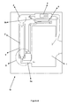
- FIG 1 shows an exemplary household appliance with drying function (G) comprising at least one drum (1).
- the drying system of this household appliance (G) comprises at least one condenser (2), at least one air blower (3) and at least one heater (4).
- the humid air in the drum (1) enters into the condenser (2) through at least one air canal (5a).
- the air, which is condensed and dehumidified in the condenser (2) by giving off heat, is passed through the heater (4) by means of the air blower (3) positioned at the condenser (2) outlet.
- the air heated by the heater (4) returns to the drum (1) thereby completing the drying cycle which is continued cyclically.
- the humidity condensed in the condenser (2) is discharged through at least one drainage hole (not shown) provided in the appliance (G).
- Household appliance (G) of the invention comprises at least one additional condenser (6) positioned between the air canal (5b) at the outlet of the air blower and the condenser (2).
- Part of the cool air blown by the air blower (3) is diverted to the heater (4) for continuation of the drying function whereas an amount of air passes through said air canal (5b) located at the outlet of the blower (3) and enters into this additional condenser (6).
- the air cooled and dehumidified in the condenser (6) is returned again to the condenser (2) and mixes with the hot and humid air coming to the condenser (2) from the drum (1). In this way, more efficient cooling and condensing of the air, coming from the drum (1), in the condenser (2) is ensured.
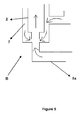
- said appliance (G) comprises at least one housing (7) in which the condenser (2) of the drying system is placed. At least one end of the air canal (5b) located at the outlet of the air blower (3) communicates with this housing (7). In this way, the air that is diverted to the housing (7), in which the condenser (2) is placed, by means of the air blower (3) contacts outer surface of the condenser (2) and cools this surface, ensuring that the hot air passing through the condenser (2) cools and releases more humidity and moves toward the condenser (2) inlet shown by Figure 5 in detail.
- Hot and humid air coming from the drum (1) through the other air canal (5a) mixes with the lightly humid, saturated, cool air which cools the condenser and the air is further cooled before entering into the condenser (2).
- the air entering into the drum (1) is condensed more and drying efficiency is enhanced.
- the air that released humidity and is cooled in the additional condenser (6) which is positioned between the condenser (2) and the air canal (5b) at the air blower (3) outlet, is diverted to said housing (7).
- the air that is passed through the additional condenser (6) and is diverted to housing (7) by means of the air blower (3) contacts the outer surface of the condenser (2) and cools this surface and moves toward the condenser (2).
- Hot and humid air coming from the drum (1) through the other air canal (5a) mixes with this air, which comes from the air blower (3) and cools the outer surface of the condenser (2), and condenses more in the condenser (2), enhancing efficiency of drying.
Landscapes
- Engineering & Computer Science (AREA)
- Textile Engineering (AREA)
- Drying Of Solid Materials (AREA)
- Detail Structures Of Washing Machines And Dryers (AREA)
Applications Claiming Priority (1)
| Application Number | Priority Date | Filing Date | Title |
|---|---|---|---|
| TR2010/06967A TR201006967A2 (tr) | 2010-08-20 | 2010-08-20 | Kurutma işlevi içeren bir ev gereci. |
Publications (1)
| Publication Number | Publication Date |
|---|---|
| EP2420612A1 true EP2420612A1 (fr) | 2012-02-22 |
Family
ID=44512688
Family Applications (1)
| Application Number | Title | Priority Date | Filing Date |
|---|---|---|---|
| EP11175557A Withdrawn EP2420612A1 (fr) | 2010-08-20 | 2011-07-27 | Appareil domestique doté d'une fonctionnalité de séchage |
Country Status (2)
| Country | Link |
|---|---|
| EP (1) | EP2420612A1 (fr) |
| TR (1) | TR201006967A2 (fr) |
Citations (5)
| Publication number | Priority date | Publication date | Assignee | Title |
|---|---|---|---|---|
| EP0163265A2 (fr) * | 1984-05-26 | 1985-12-04 | Miele & Cie. GmbH & Co. | Séchoir à tambour pour linge |
| US6434857B1 (en) * | 2000-07-05 | 2002-08-20 | Smartclean Jv | Combination closed-circuit washer and drier |
| US20060179681A1 (en) * | 2003-09-25 | 2006-08-17 | Matsushita Electric Industrial Co., Ltd. | Heat pump type drying apparatus drying apparatus and drying method |
| WO2007023510A1 (fr) | 2005-08-25 | 2007-03-01 | Renzacci S.P.A. Industria Lavatrici | Sèche-linge |
| WO2010006081A1 (fr) | 2008-07-08 | 2010-01-14 | Chiaro Technologies, Inc. | Localisation de multiples canaux |
-
2010
- 2010-08-20 TR TR2010/06967A patent/TR201006967A2/xx unknown
-
2011
- 2011-07-27 EP EP11175557A patent/EP2420612A1/fr not_active Withdrawn
Patent Citations (5)
| Publication number | Priority date | Publication date | Assignee | Title |
|---|---|---|---|---|
| EP0163265A2 (fr) * | 1984-05-26 | 1985-12-04 | Miele & Cie. GmbH & Co. | Séchoir à tambour pour linge |
| US6434857B1 (en) * | 2000-07-05 | 2002-08-20 | Smartclean Jv | Combination closed-circuit washer and drier |
| US20060179681A1 (en) * | 2003-09-25 | 2006-08-17 | Matsushita Electric Industrial Co., Ltd. | Heat pump type drying apparatus drying apparatus and drying method |
| WO2007023510A1 (fr) | 2005-08-25 | 2007-03-01 | Renzacci S.P.A. Industria Lavatrici | Sèche-linge |
| WO2010006081A1 (fr) | 2008-07-08 | 2010-01-14 | Chiaro Technologies, Inc. | Localisation de multiples canaux |
Also Published As
| Publication number | Publication date |
|---|---|
| TR201006967A2 (tr) | 2011-06-21 |
Similar Documents
| Publication | Publication Date | Title |
|---|---|---|
| EP2702199B1 (fr) | Seche linge a pompe thermique | |
| EP2723928B1 (fr) | Machine à laver et à sécher le linge dotée d'un condensateur refroidi à l'air | |
| EP2702198B1 (fr) | Sèche-linge à pompe de chaleur | |
| US9803312B2 (en) | Dryer with heat pump | |
| EP2519686B1 (fr) | Sèche-linge à pompe à chaleur | |
| EP2938777B1 (fr) | Sèche-linge comprenant un dispositif de pulvérisation | |
| EP2725133A2 (fr) | Machine à laver | |
| EP2449164B1 (fr) | Sèche-linge dont l'efficacité de séchage est accrue | |
| EP3077586B1 (fr) | Séchoir avec pompe à chaleur | |
| CN106192322A (zh) | 一种冷凝干衣机及冷凝干衣方法 | |
| GB2375812A (en) | Drying apparatus with heat exchanger and heat pump | |
| EP2570546B1 (fr) | Sèche-linge avec système de pompe à chaleur | |
| EP2458068B1 (fr) | Équipement de séchage du linge comportant un ventilateur | |
| WO2017174766A1 (fr) | Machine à laver et/ou sécher le linge à pompe à chaleur | |
| WO2016107699A1 (fr) | Machine à laver et à sécher le linge comprenant un condenseur refroidi par air | |
| EP2855756B1 (fr) | Sèche-linge ayant un condenseur refroidi par air | |
| EP2420612A1 (fr) | Appareil domestique doté d'une fonctionnalité de séchage | |
| WO2015074836A1 (fr) | Sèche-linge | |
| WO2013182403A1 (fr) | Sèche-linge ayant un condenseur refroidi à l'air | |
| WO2017194531A1 (fr) | Lave-linge/sèche-linge comprenant un condenseur à eau | |
| CN103344105A (zh) | 烘干机 | |
| ATE454492T1 (de) | Wäschetrockner mit einer sekundären kondensationeinheit | |
| WO2025198554A1 (fr) | Système combiné comprenant un sèche-linge à condenseur | |
| WO2019129614A1 (fr) | Échangeur de chaleur | |
| WO2019105524A1 (fr) | Sèche-linge avec un système de pompe à chaleur |
Legal Events
| Date | Code | Title | Description |
|---|---|---|---|
| AK | Designated contracting states |
Kind code of ref document: A1 Designated state(s): AL AT BE BG CH CY CZ DE DK EE ES FI FR GB GR HR HU IE IS IT LI LT LU LV MC MK MT NL NO PL PT RO RS SE SI SK SM TR |
|
| AX | Request for extension of the european patent |
Extension state: BA ME |
|
| PUAI | Public reference made under article 153(3) epc to a published international application that has entered the european phase |
Free format text: ORIGINAL CODE: 0009012 |
|
| STAA | Information on the status of an ep patent application or granted ep patent |
Free format text: STATUS: THE APPLICATION IS DEEMED TO BE WITHDRAWN |
|
| 18D | Application deemed to be withdrawn |
Effective date: 20120823 |